To my other GT6 pages
October 10, 2022
Accelerator Shaft
Inline cylinder engines, if not installed cross-wise, necessarily have
their fuel/air induction systems on one side of the car or the
other. On all of the LBC engines I'm familiar with, this is on the
right side. This is fine, except that by far most of these cars
are left-hand drive, which means that the control mechanism for the
throttles has to span across the car, left to right. For Triumphs
of this era, this was commonly accomplished with a shaft running behind
the engine with the accelerator pedal on the left end, and an actuating
arm on the right end. If we're lucky, like in the TR6, this shaft
can be a straight in the engine compartment, but the GT6 is not so
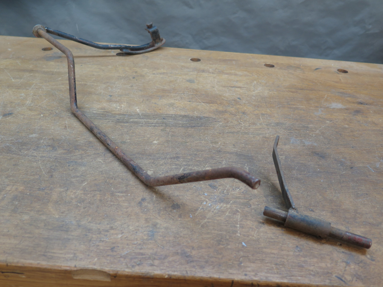
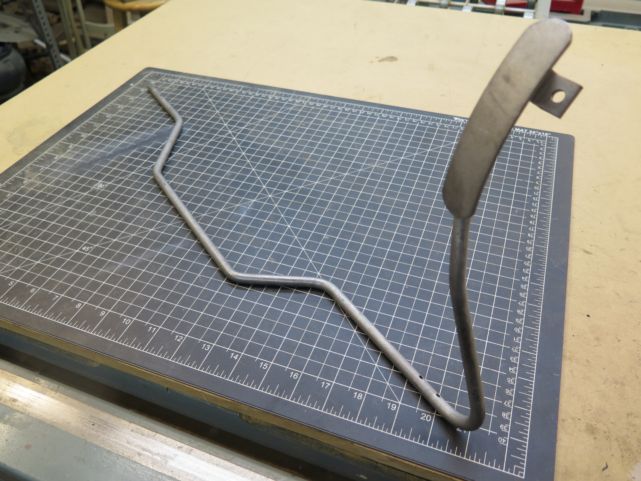
fortunate. The rod has to jog around the rear of the engine,
yielding a pretty gangly looking piece of kit.
My rod was rusty but all present. When trying to remove the part
from the car a few years ago, I found the actuator arm seized to the
shaft, so it was captive. At the time, I chose to just cut the
shaft and deal with it later. Well, I guess later is now.
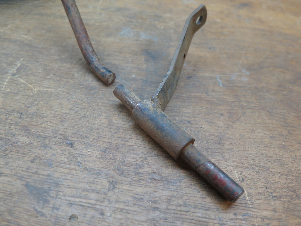
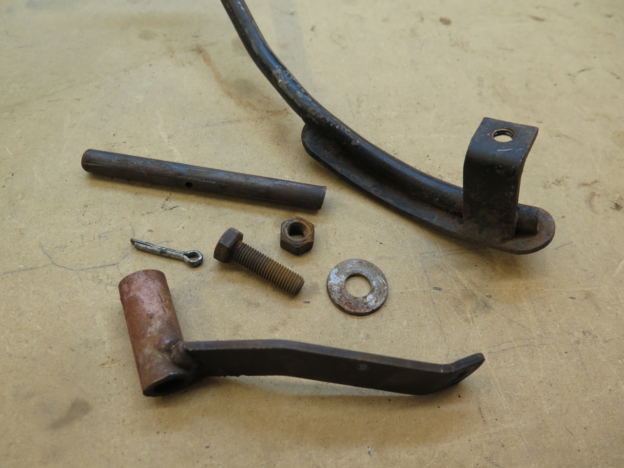
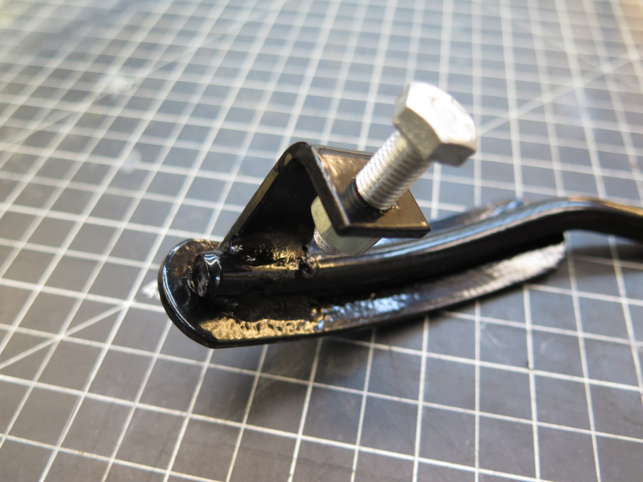
Some heat and persuasion finally got the arm off. The only other
removable part from the assembly is the stop bolt behind the pedal.
To put the shaft back together, it seemed that alignment and clocking
would both be important. I could ascertain from the hacksawn ends
how the two pieces had to be clocked, and a long aluminum channel served
as a strongback to help maintain co-linearity of the two ends.
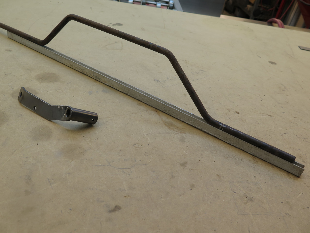
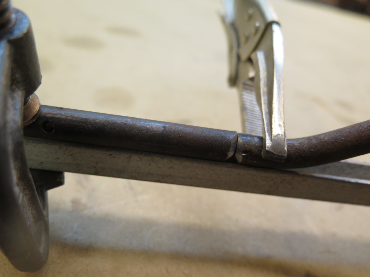
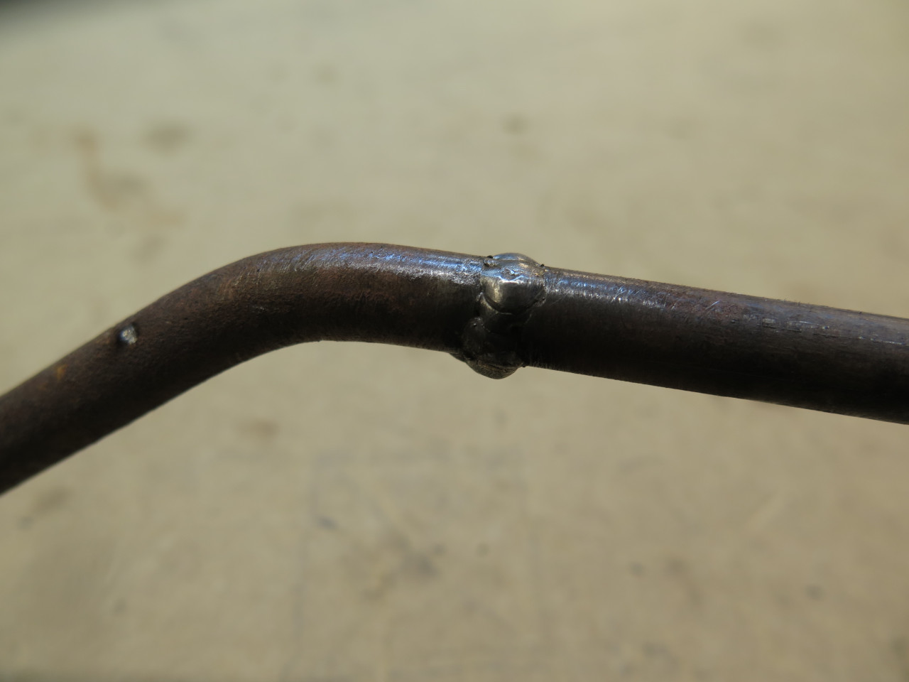
A few pops with the MIG, and it was back to one piece.
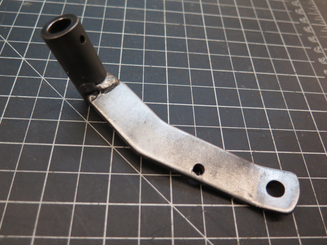
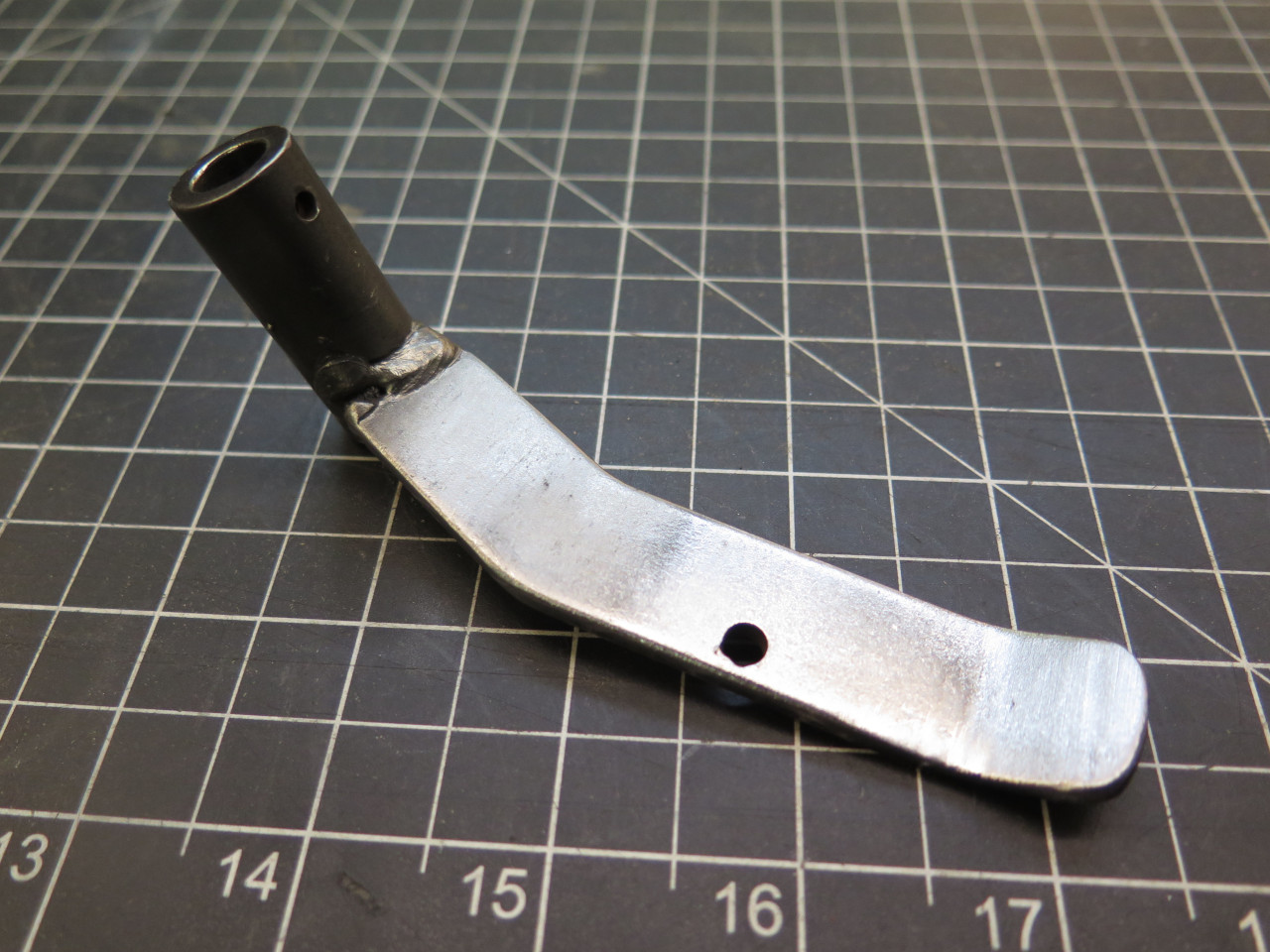
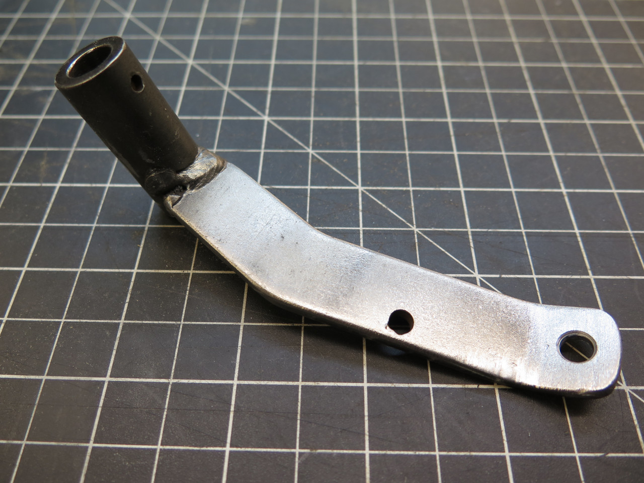
The actuator arm was OK, but the hole for the throttle linkage looked a
little generous. Measuring it and the linkage rod confirmed that
the hole was pretty hogged out. A few more MIG hits filled the
hole. Some grinding and drilling and we had a much more
appropriate hole.
Next job was to test fit the shaft so I could see what I could do about
bushings and other hardware. I envisioned a ten minute job, but an
hour later, I was still struggling with that freaking shaft. Now,
maybe there is some theoretical way to thread that shaft through
its driver's side hole with the engine, steering column, and other
pedals all in place, but I couldn't find it. In desperation, I
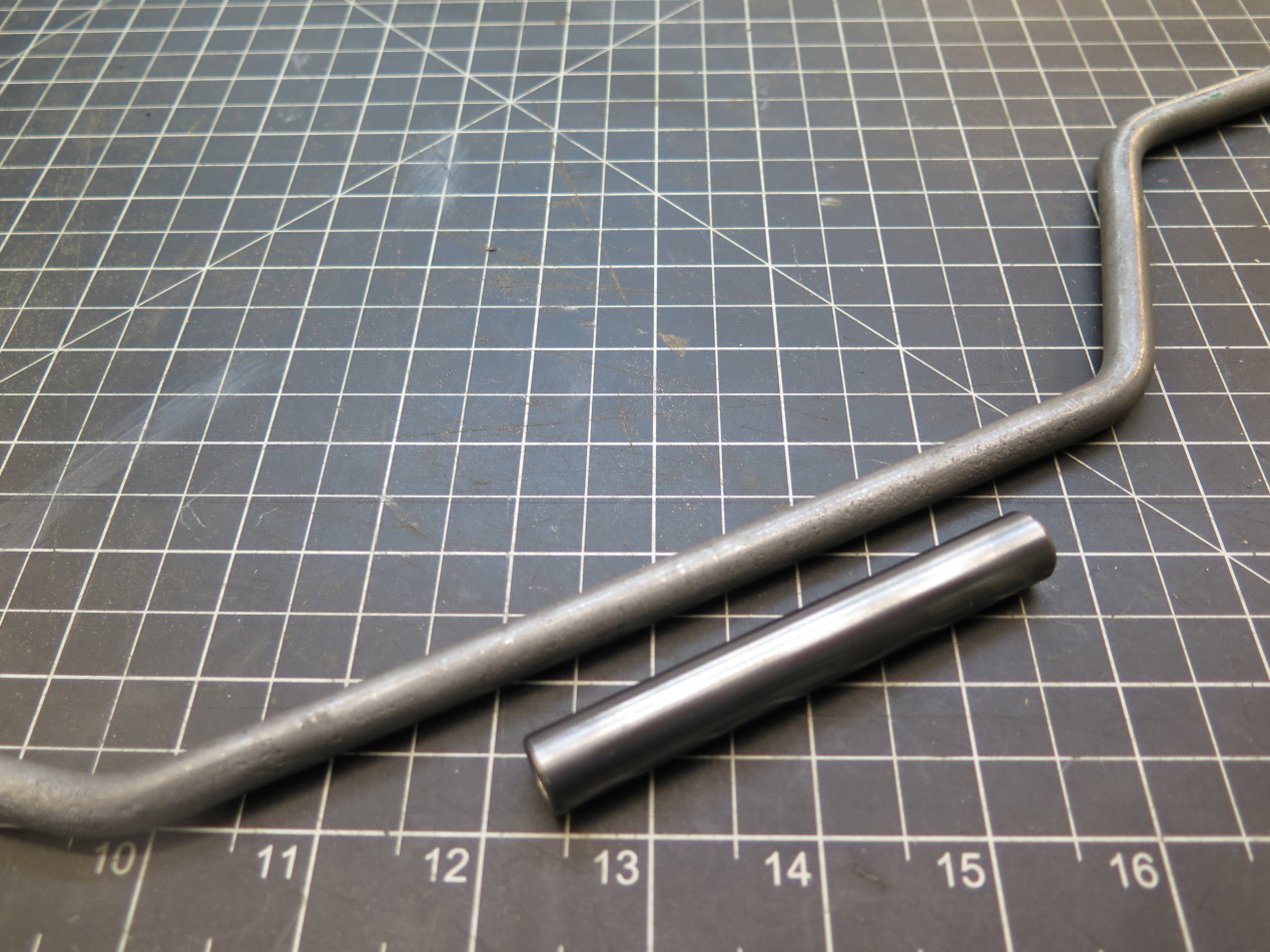
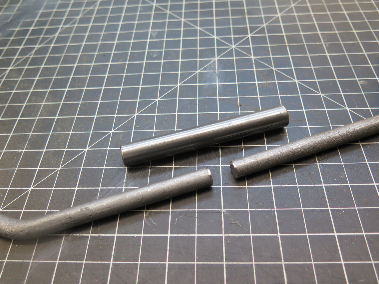
opted for the nuclear option: I cut the shaft in two. I cut
it in the center of the jogged portion. I concluded later that
another place for the cut would have been much better, but this one
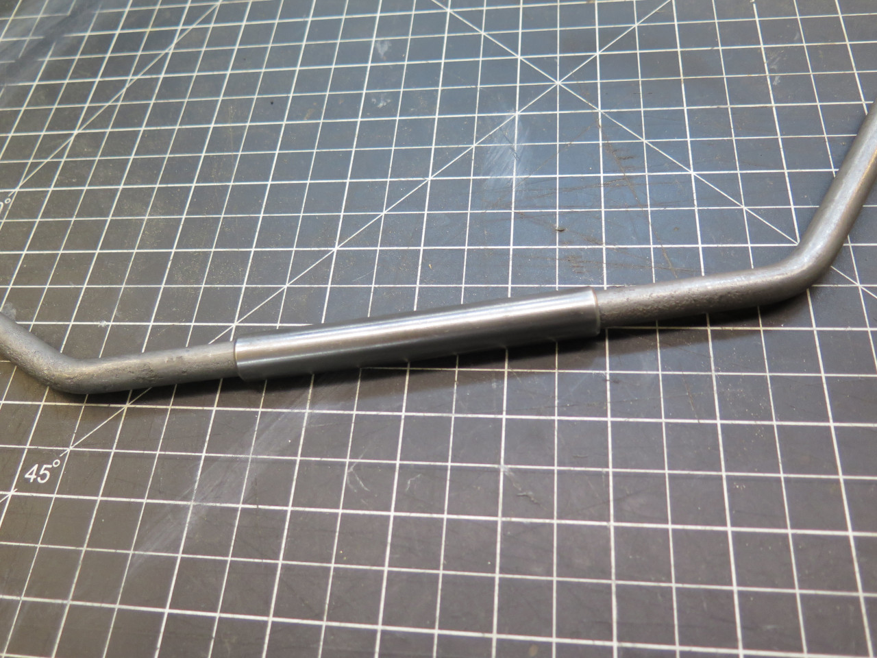
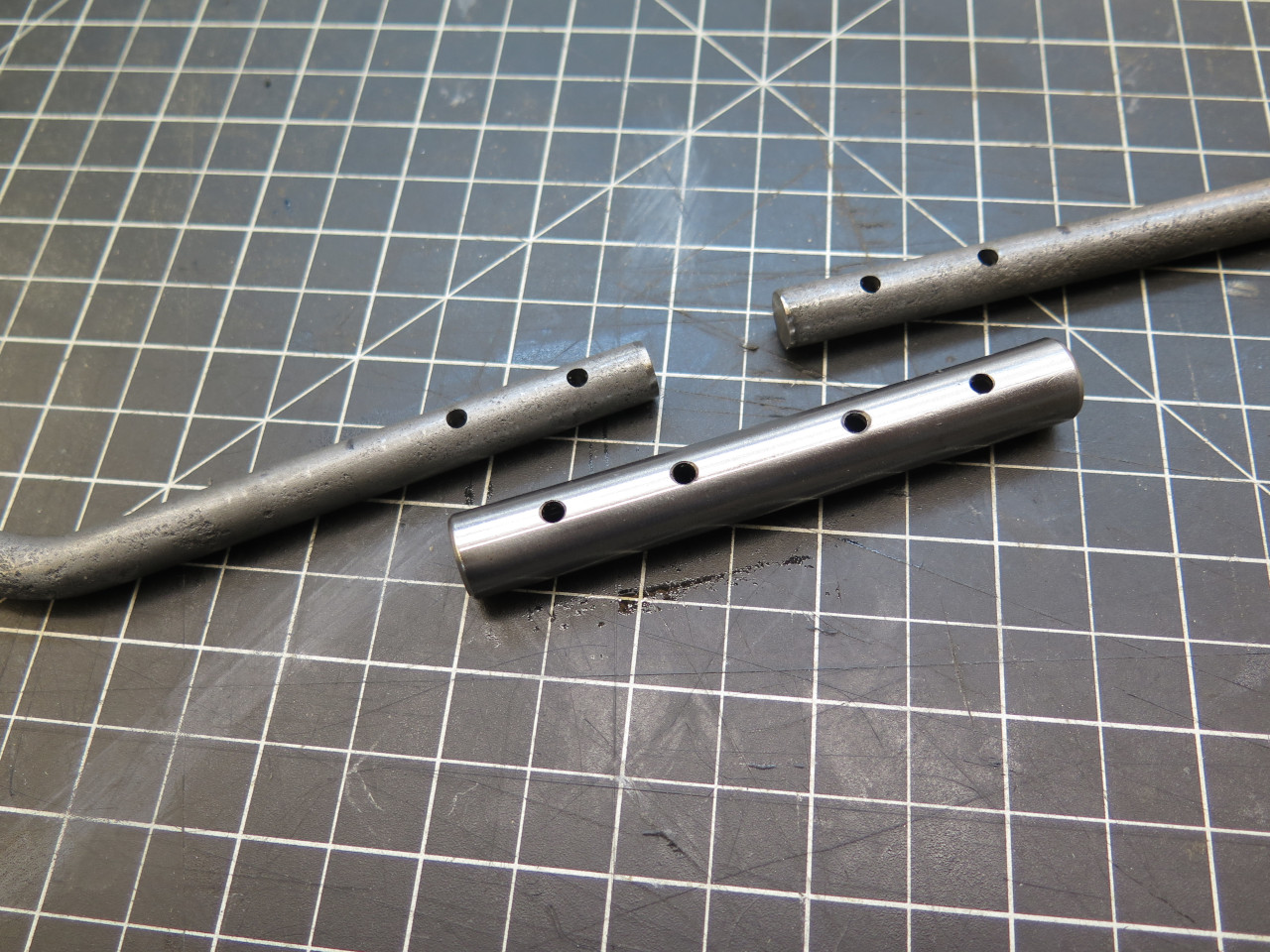
worked. Before the cut, I made sure I had a suitable tube to act
as a splice. Four roll pins will hold everything together.
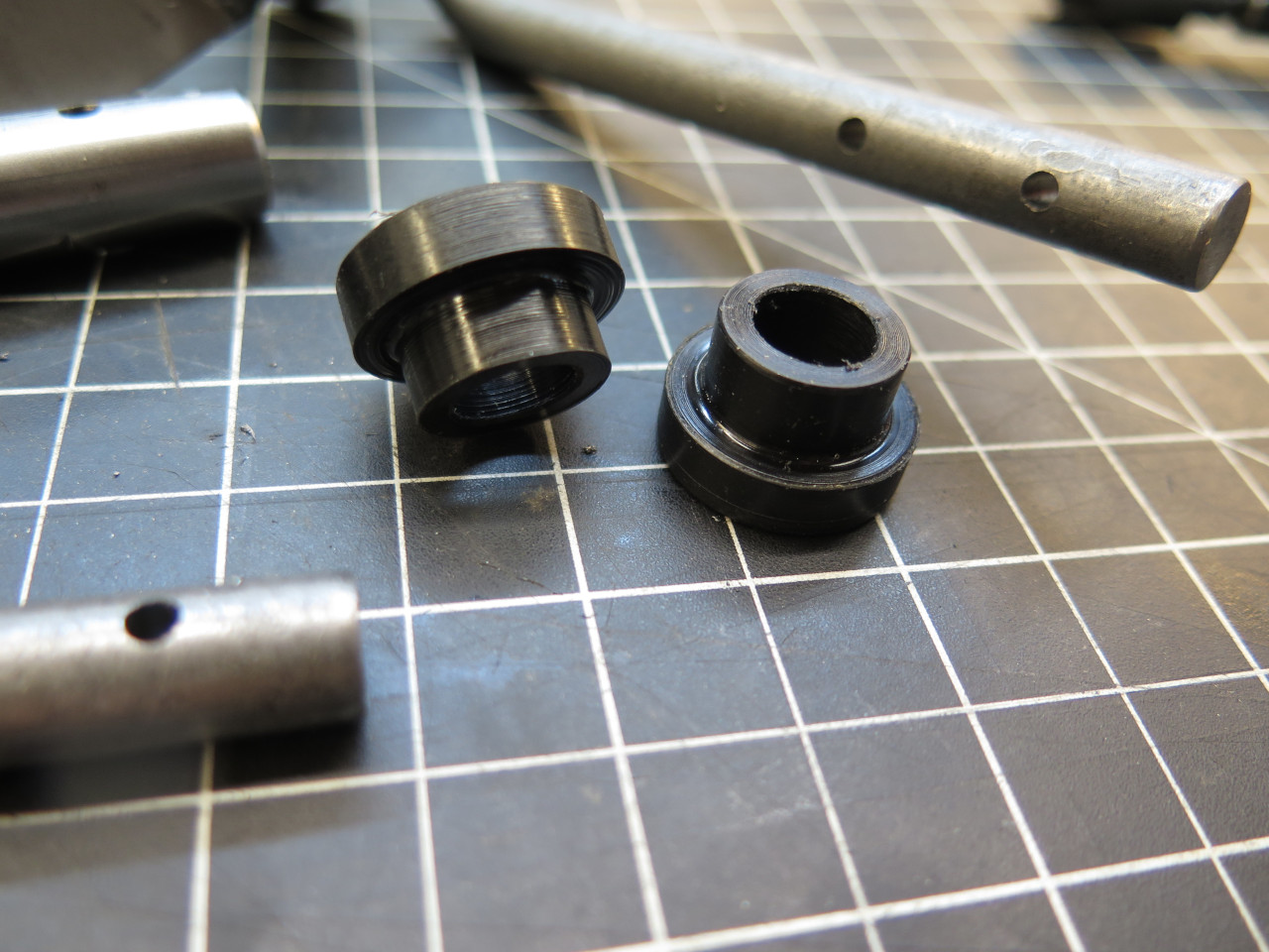
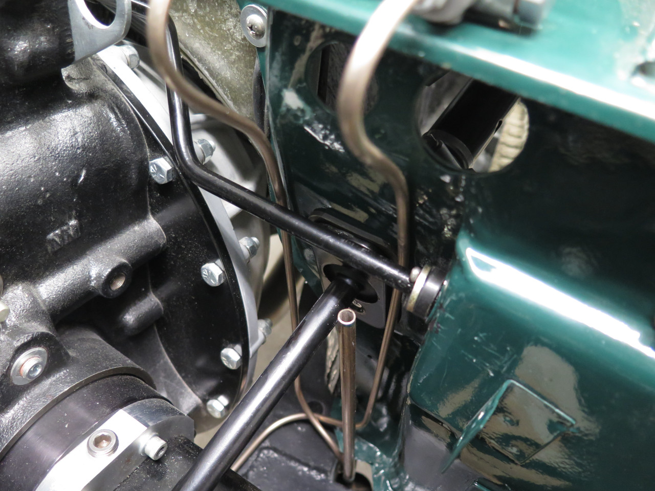
The shaft was designed to ride in a pair of grommets or bushings, one
where the shaft passes through the firewall on the driver's side, and
one on the passenger side for the far end of the shaft. I don't
really know what the factory bushings looked like because mine were long
gone. There are apparently folks who would happily sell me a kit
including some plastic bushings and other hardware to hold the shaft,
but it looked like a pretty simple job to just cobble something on the
spot.
These bushes are made from nylon, mainly because of nylon's natural lubricity.
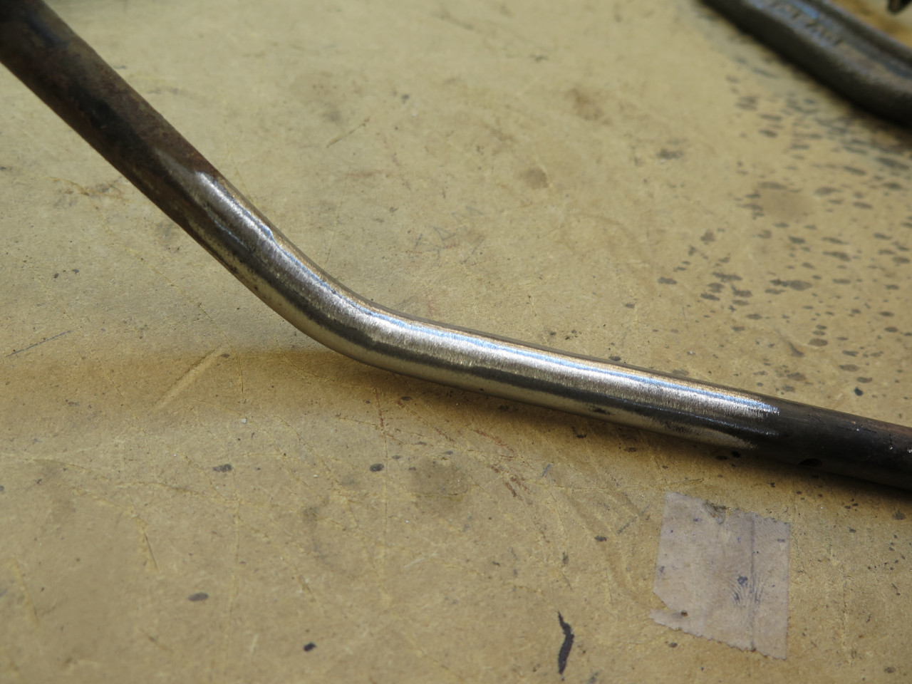
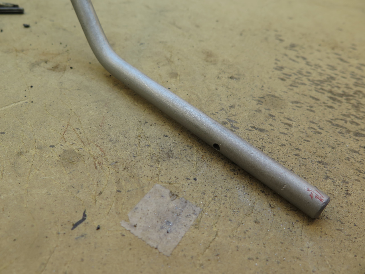
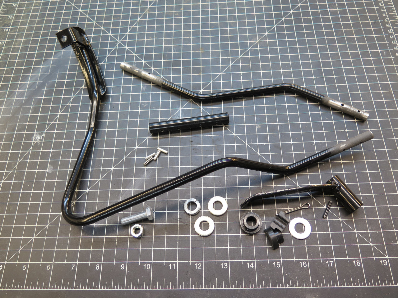
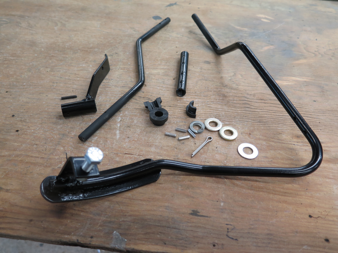
So, here are all of the parts. I powder coated the shaft, the
coupling sleeve, and the actuating arm. Powder coat goes on fairly
thick though, so the arm and the splice no longer fit. I sanded
off most of the powder coat in those areas, and applied some
conventional paint.
Also, the driver's side bushing had to be cut in half since it's fit on
the shaft wouldn't allow it to negotiate the bends. This is where I
realized I should have spliced the shaft just inboard of this
bushing. That way the bush wouldn't need to be cut.
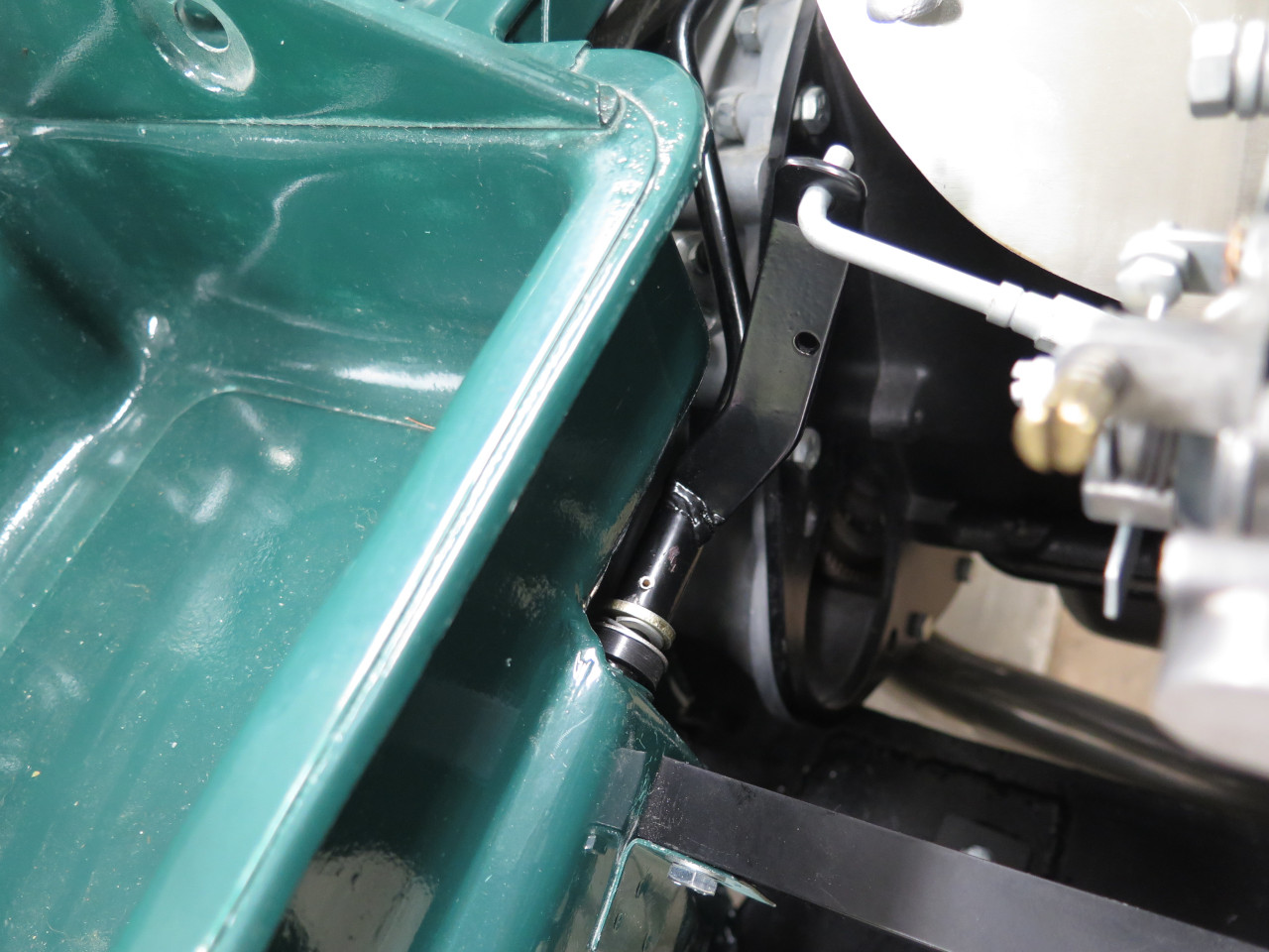
The shaft is stabilized side to side by a "thackery" spring washer on
the passenger side. I used spacer washers on both sides so that
the thackery was slightly compressed when everything was installed.
One big irritation on this job was the holes where the bushings
fit. The factory did reinforce them by spot-welding thin washers
over the holes, bit it was sloppily done. The faces where the
bushes go are not parallel to each other, and are not perpendicular to
the axis of the shaft, so the bushes don't seat well. If I had
realized this before paint, I think I would have fixed it. I guess
I'll have to try to forget about it.
The shaft runs in front of the brake lines from the PDWA. I don't
think that is the way the factory had it, but I prefer it.
This was a frustrating job. It would have been so much easier if
I'd thought to do it before the engine was in. Anyway, cost was
close to zero, and it's done.
Comments to Ed at elhollin1@yahoo.com
To my other GT6 pages