To my other GT6 pages
January 7, 2022
Dash Support
GT6 cars, along with their sibling Spitfires, and cousin TRs, all
sported a support piece that spanned between the bottom of the dashboard
and the frame. This was typically a fairly robust aluminum
casting that straddled the gearbox cover. Beside being a
convenient place for the radio and maybe some other switches, it was
apparently structural, providing some resistance to body racking,
especially in the roadsters.
I don't recall if the vinyl covering on my support was original or
something I applied back in the 80s, but either way, it was tired.
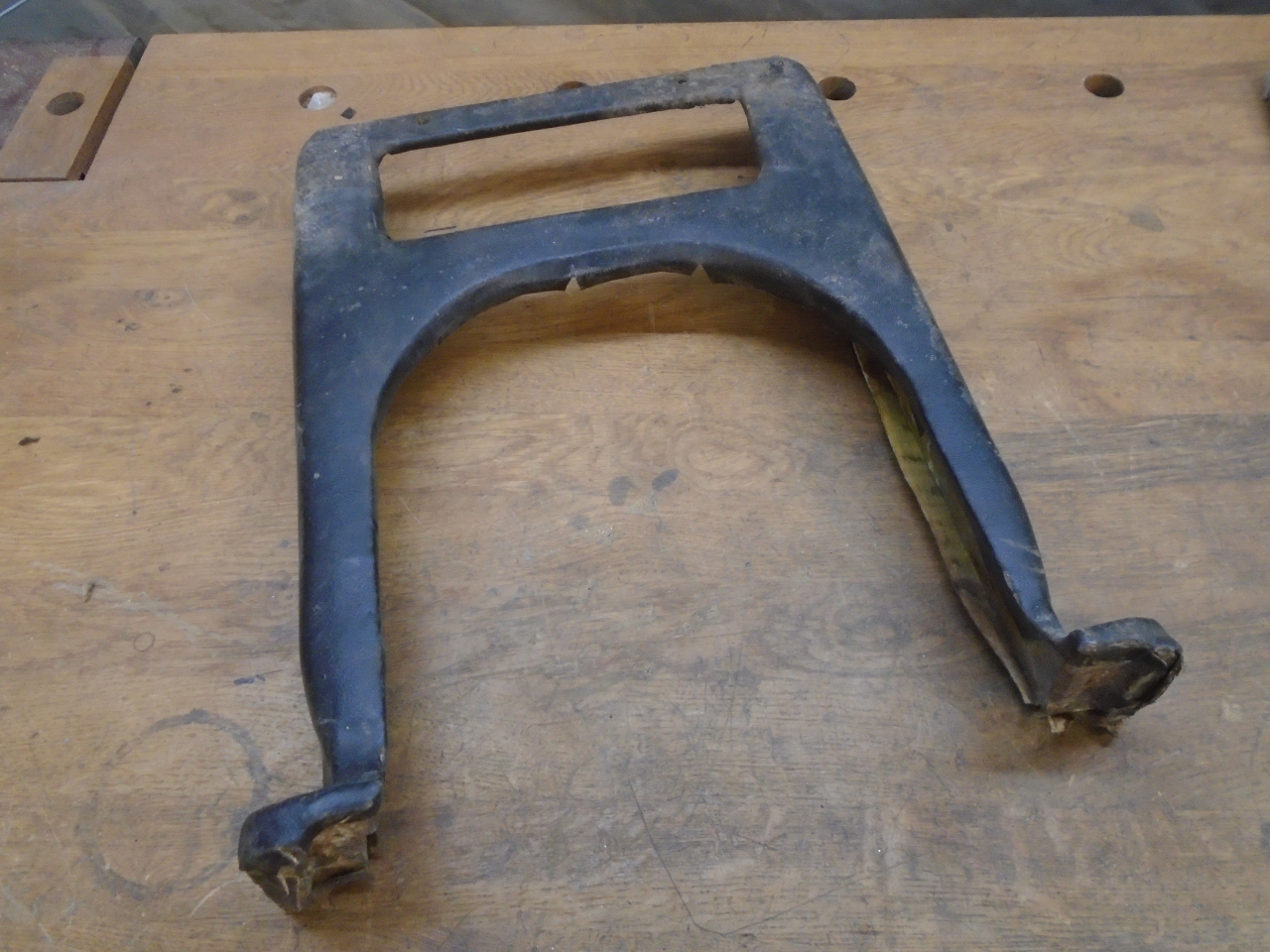
Removing the vinyl revealed a thin layer of foam.
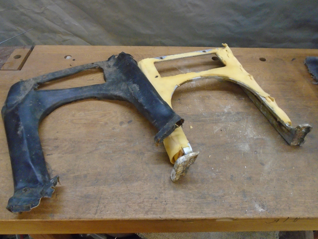
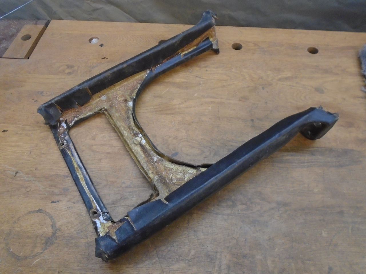
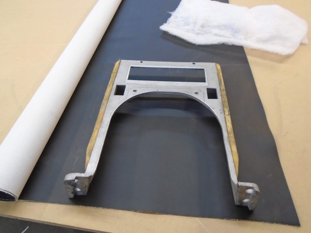
Removing all of the foam and glue, and giving the piece a light blast
cleaned it up nicely. There were molded foam pads glued the the
sided of the legs that I left in place.
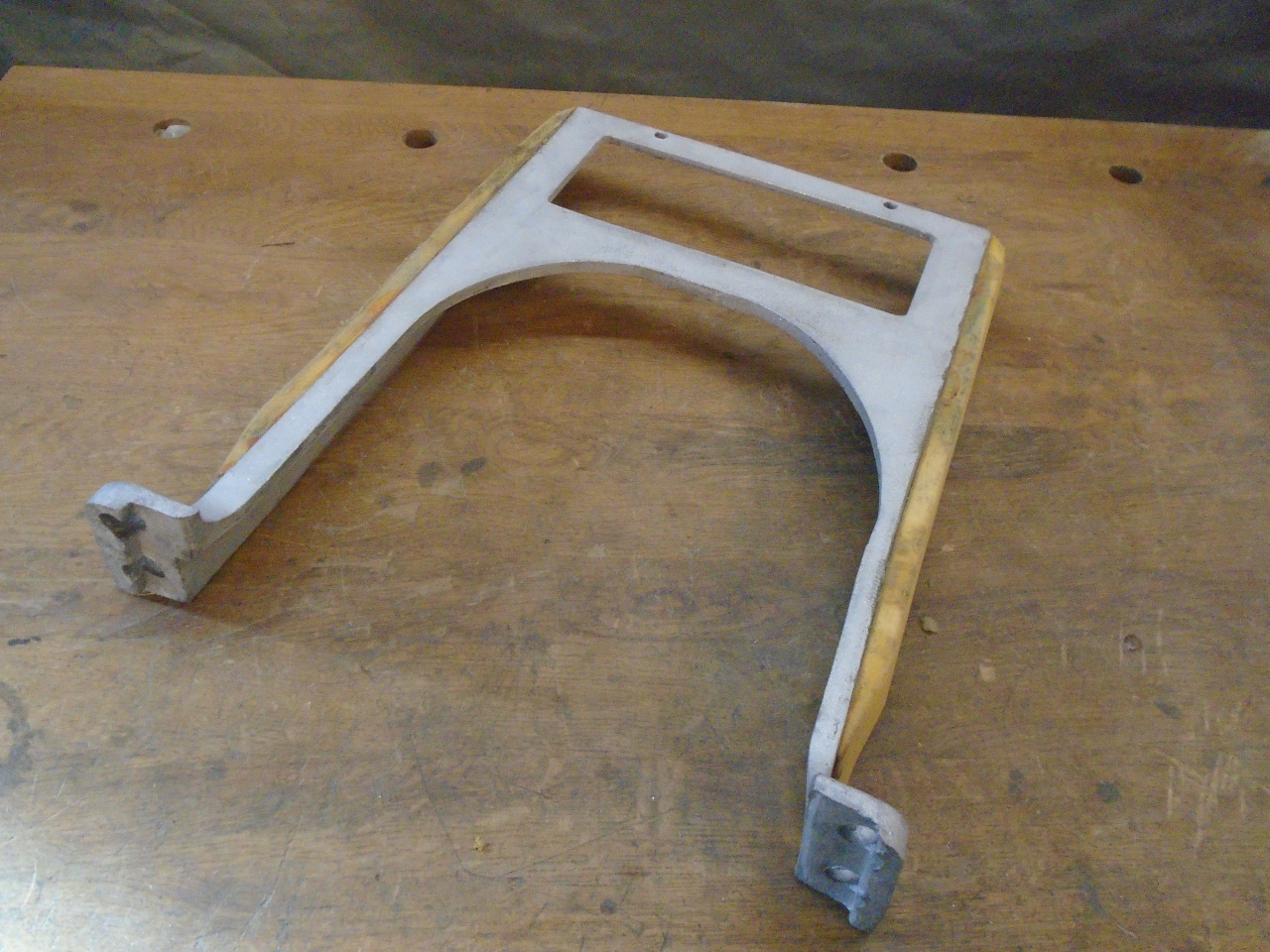
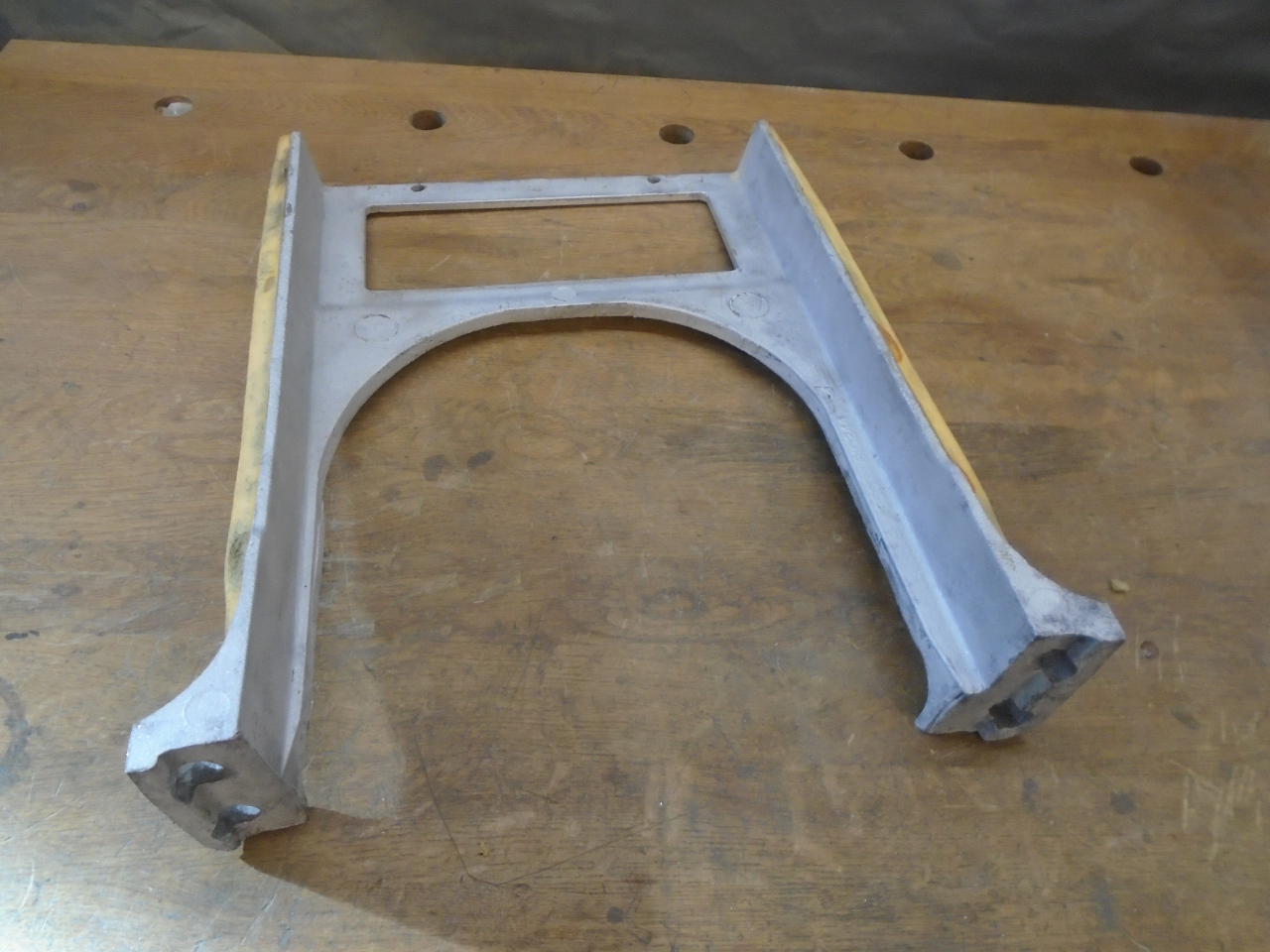
A prominent feature of the support is the cutout for the radio.
Car radios these days have standard sizes to fit in standardized
cutouts. These are specified by a German "DIN" standard, that was
later adopted as an international ISO standard, but still referred to as
DIN. A "Single DIN" cutout for a car radio is 50 x 180 mm, or
nominally 2" x 7".
The cutout in my dash support was larger than a single DIN
opening. I still have the original radio, but decided I
wanted to install something more modern. Rather than use an
adapter plate to mount a new radio, I reasoned that this was a good time
to just modify the support to provide a standard DIN opening.
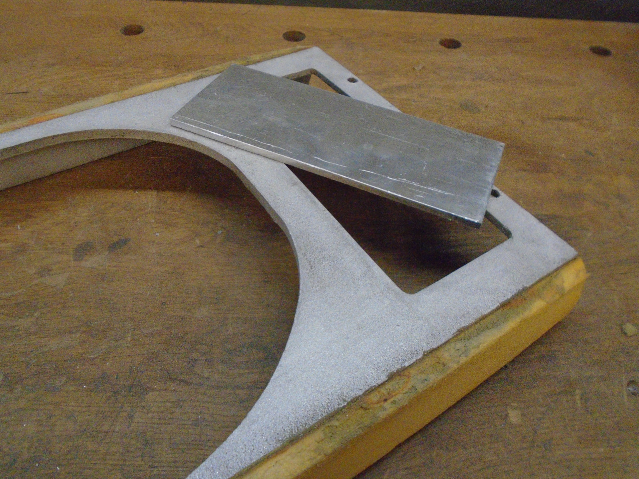
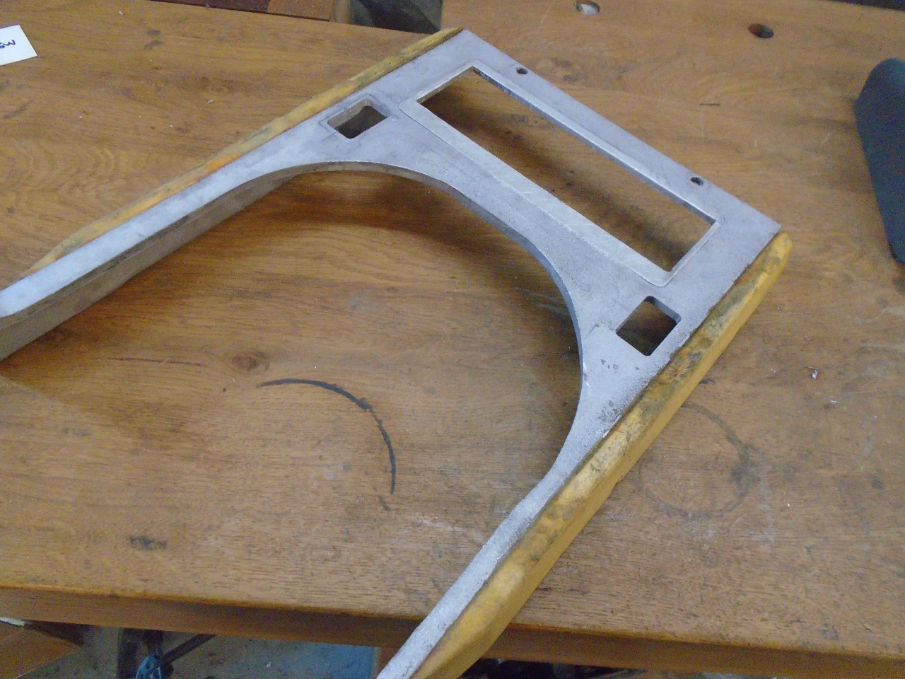
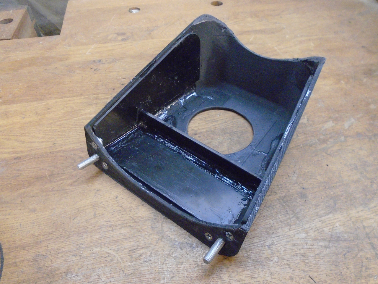
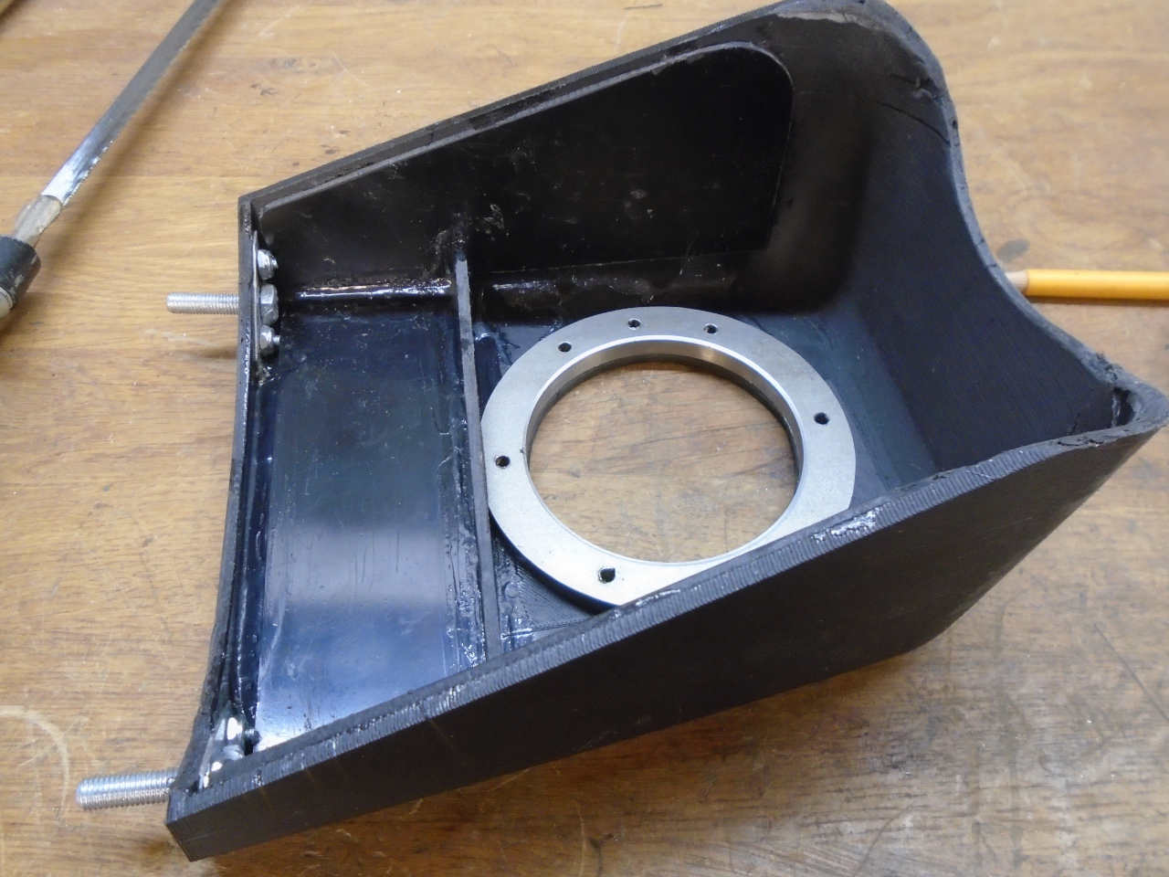
First, I filled in the existing hole. The support is right at
3/16" thick in that area, so a chunk of 3/16 aluminum plate fit
perfectly.
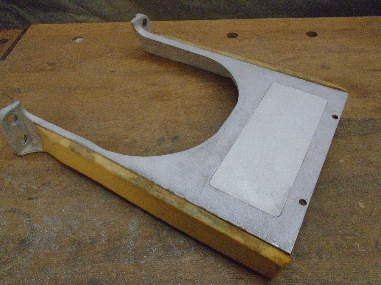
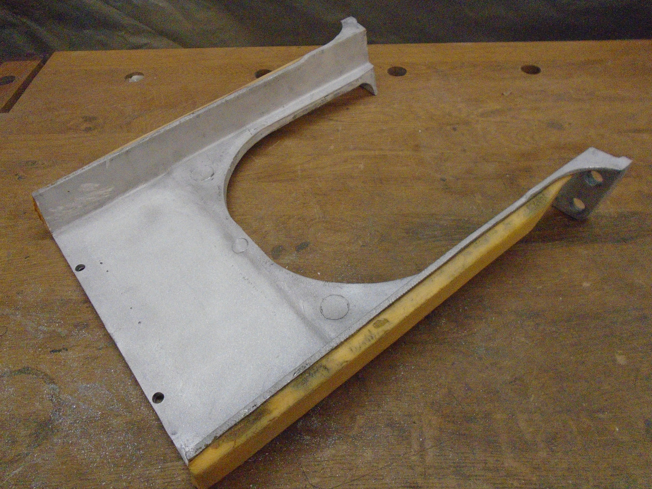
I welded the blanking plate on the back side and ground the welds flush.
A test fit in the car to determine the exact location for the radio cutout.
This is where I realized that before I could place the radio, I needed
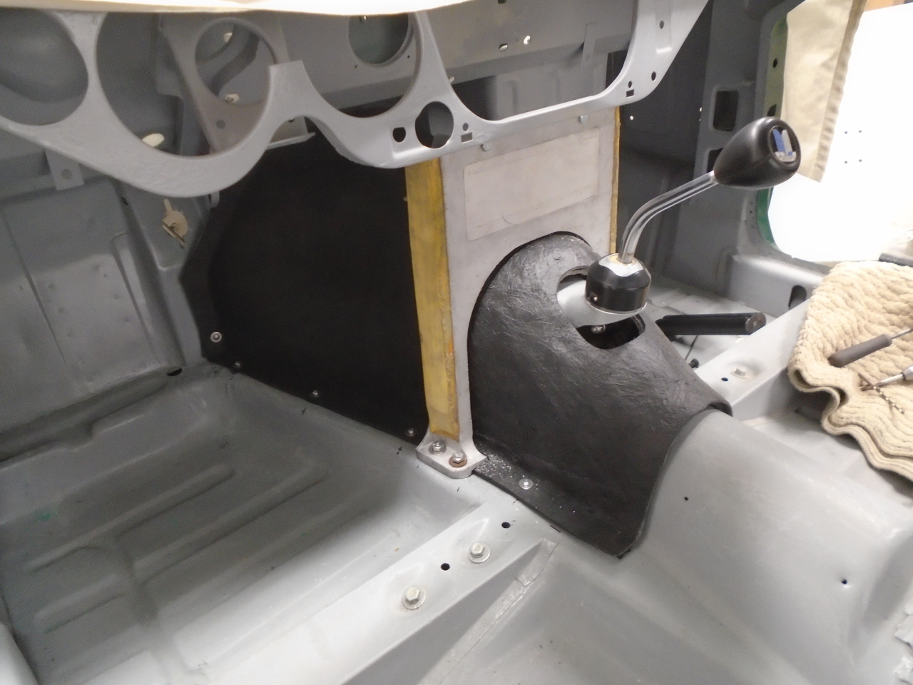
to know what I was going to do about a shifter surround. When I
made the gearbox cover,
I left off the hump that originally surrounded the opening for the
shifter. I had a few ideas about what to do, but I had to land on
one of them before I could go any further with the radio.
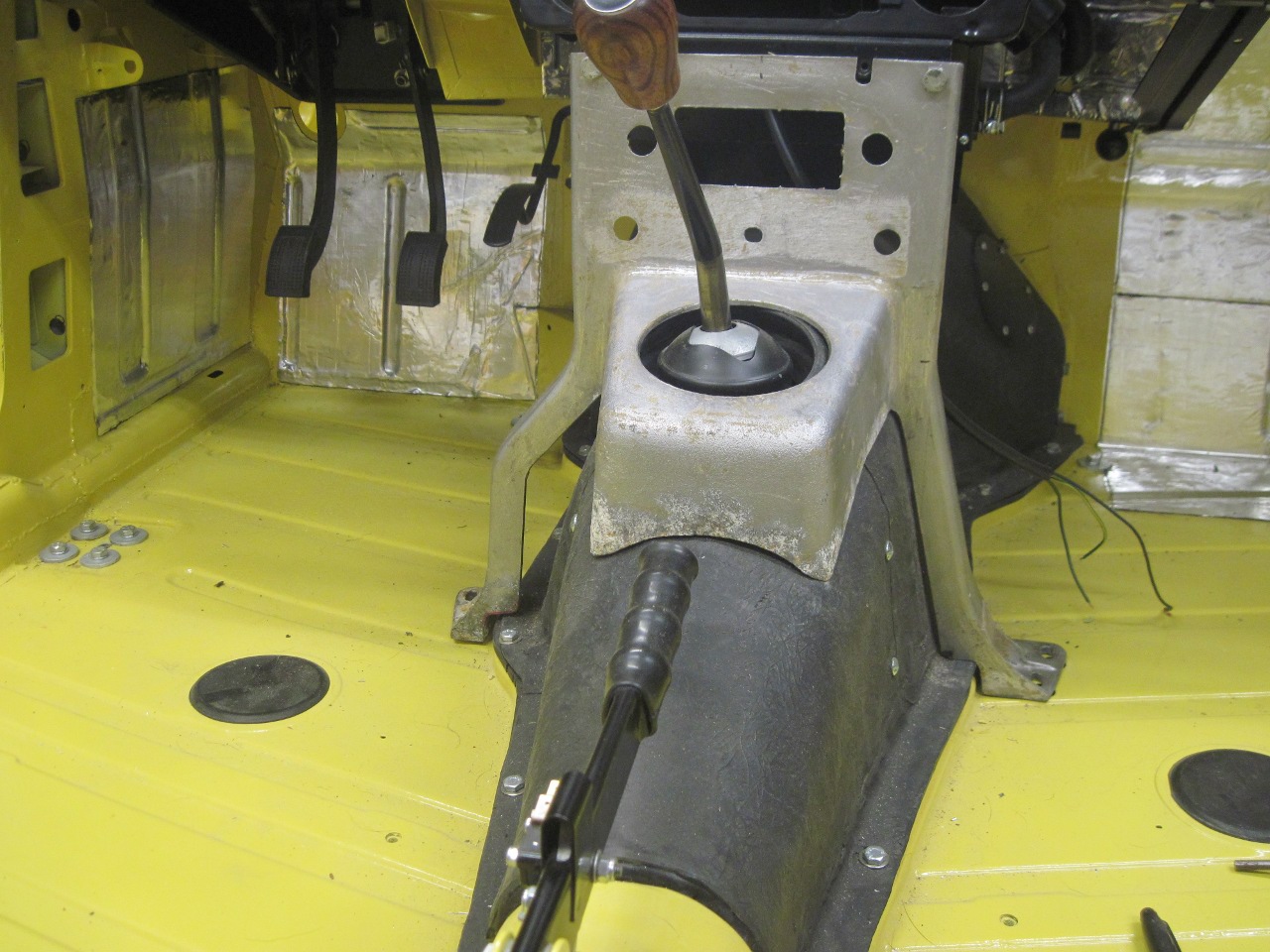
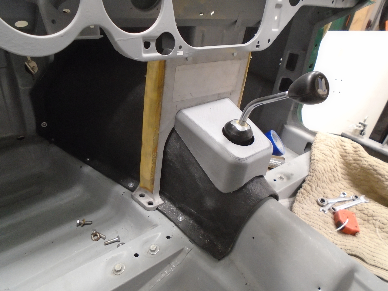
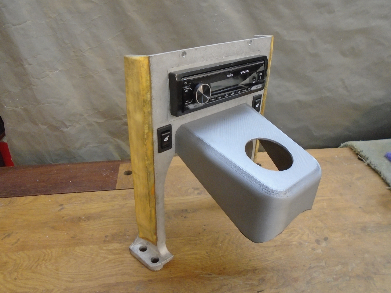
One idea I had for the shifter plinth (I think I'll call it a shifter
"plinth"), was something akin to what is in the TR6. In the TR6,
the shifter plinth is part of the dash support casting.
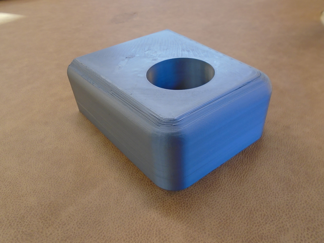
I didn't really want to modify the GT6 support that much, but I thought I
could make a similar piece that could bolt on to the support. For
prototyping parts like this, it's hard to beat a 3D printer. Here
was my first pass at a plinth. It seemed a little boxy and didn't
fit very well.
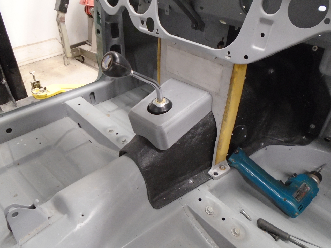
A few tweaks, and the second try was much better.
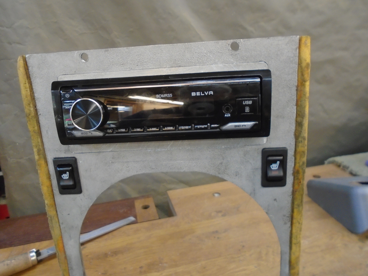
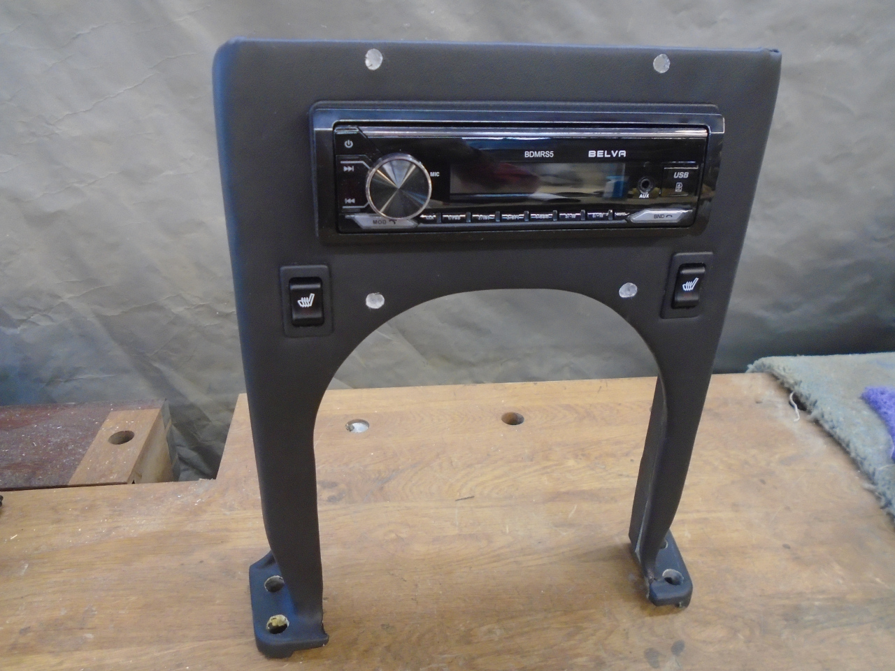
Satisfied with a plinth design, I could proceed with the radio
cutout. I also intend to put seat heaters in the car, and the
support seemed like a good place for the switches. A test layout:
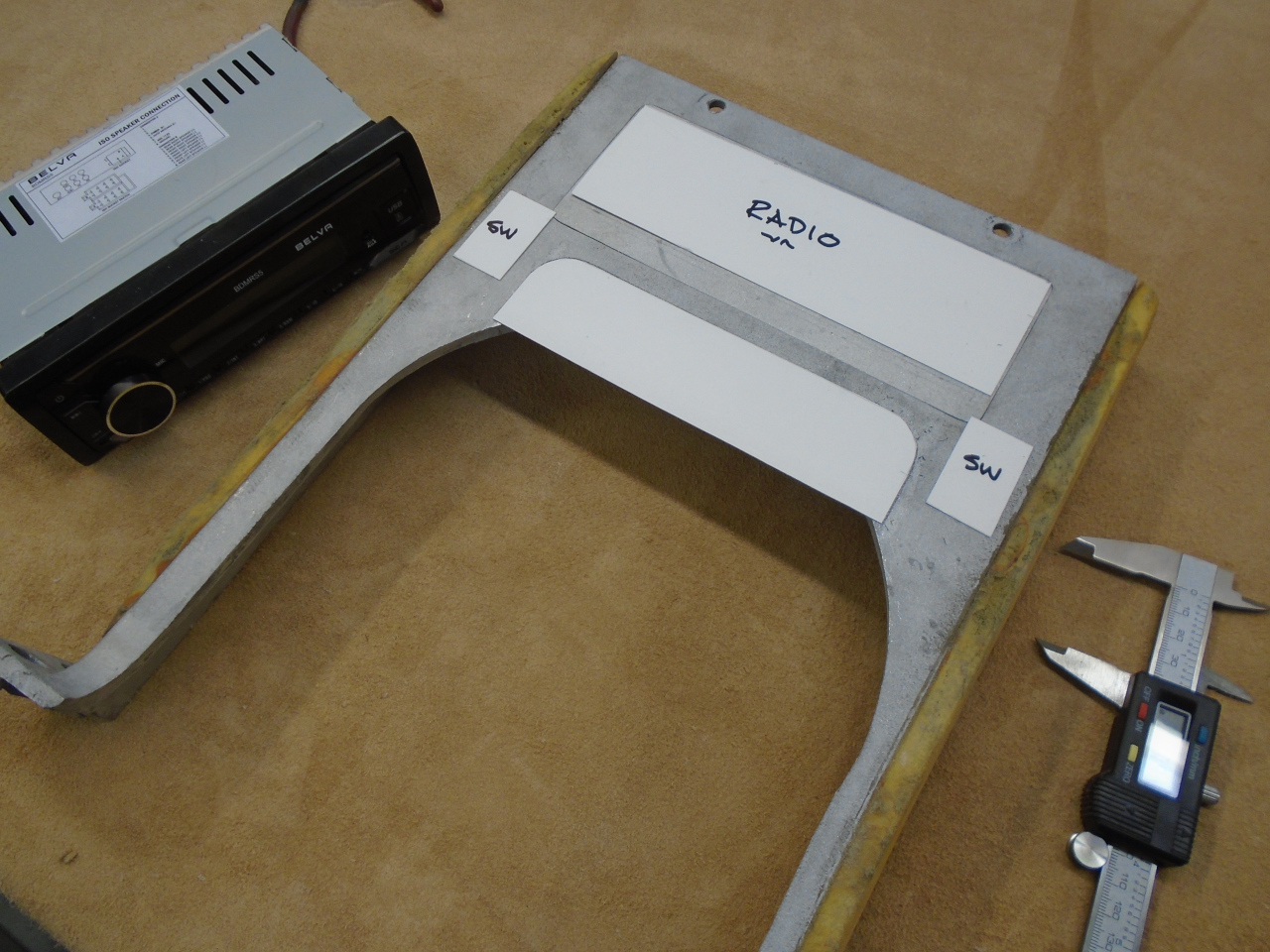
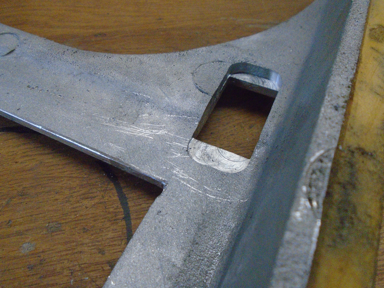
I cut the DIN hole a little oversized to account for the thickness of
vinyl that will wrap around the edges. Likewise for the seat
heater switch cutouts. The switch cutouts had to be relieved a
little on the backside since the switches wouldn't snap in to a panel
that thick. I bought a cheap radio for mockup. If it works
well enough, I'll use it.
The 3D printed test plinths were made with PLA plastic, which is
easy to print, but isn't very strong, and can degrade over time.
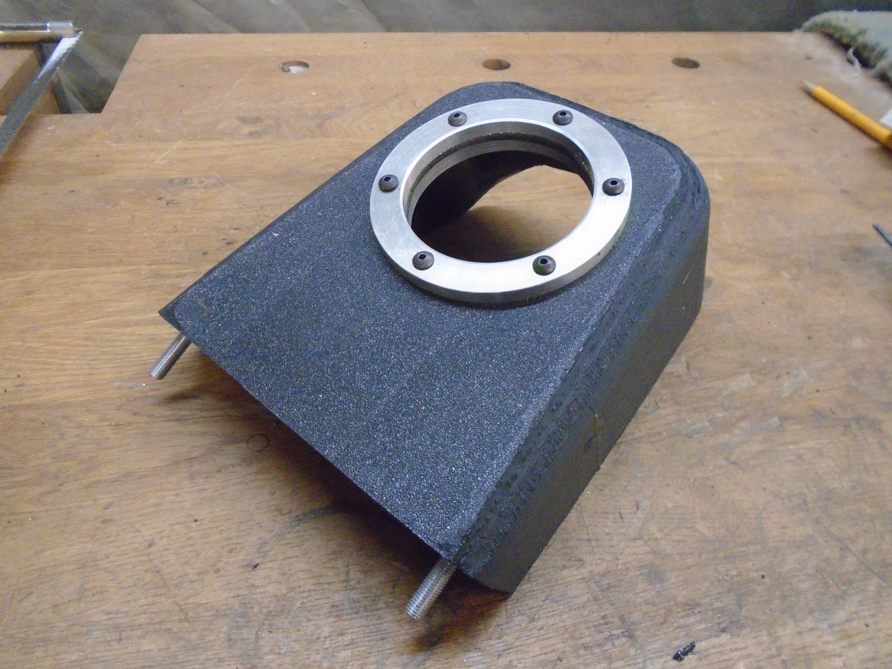
It was time to print the real thing, for which I chose ABS, and settings
that would give a better quality finish. This last print took
over 17 hours.
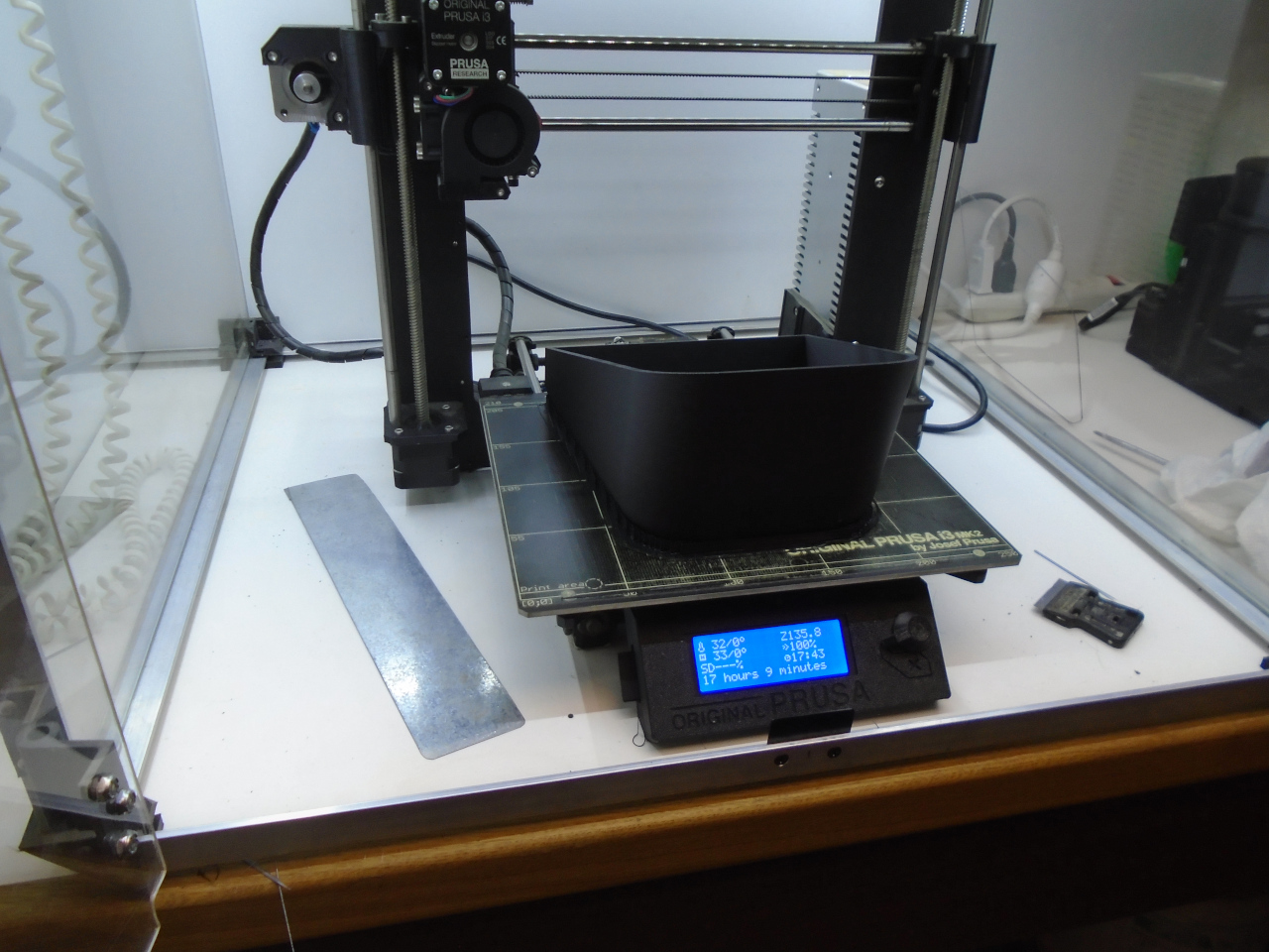
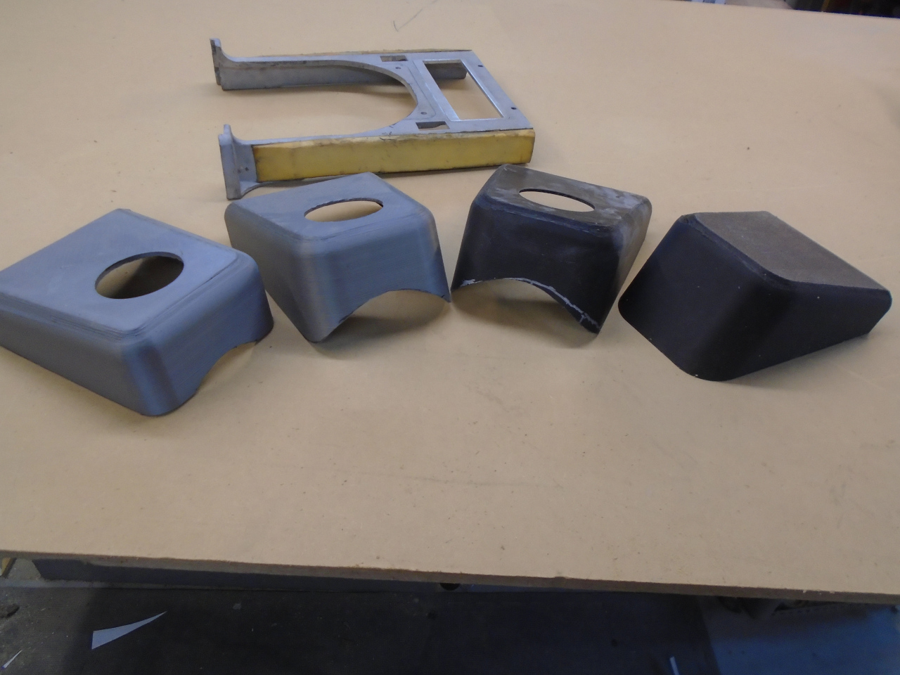
There were four iterations all together, the quickest one at around 12 hours. Most of the printing was over night, though.
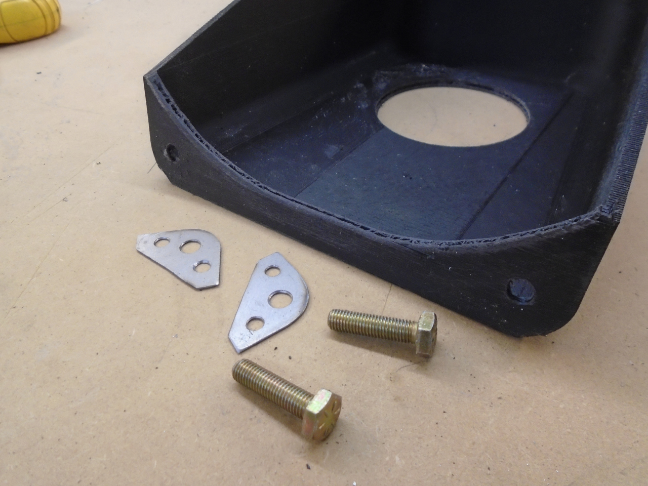
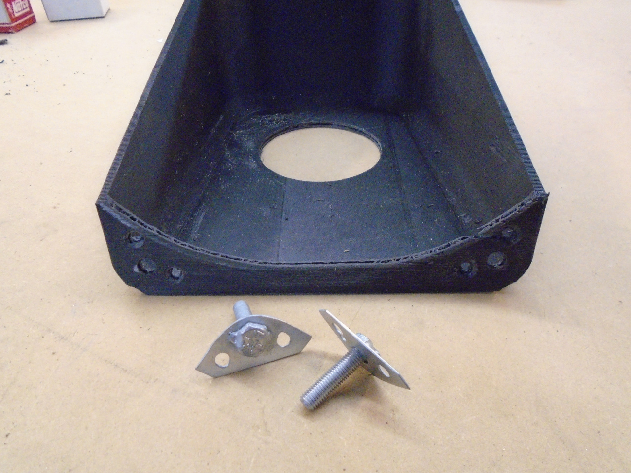
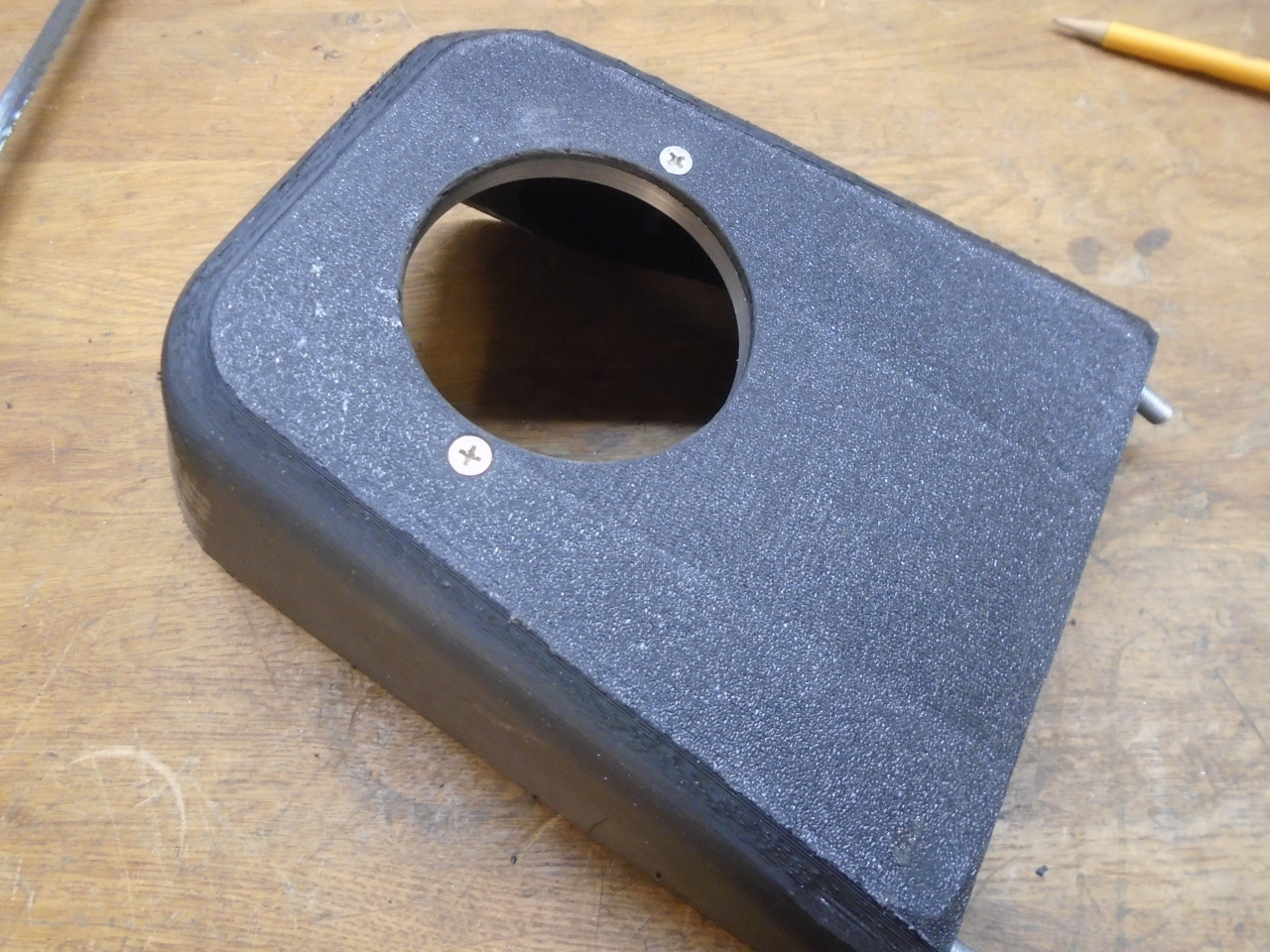
I had to figure out a way to fasten the plinth to the support. I made these little gizmos and epoxied them in the corners.
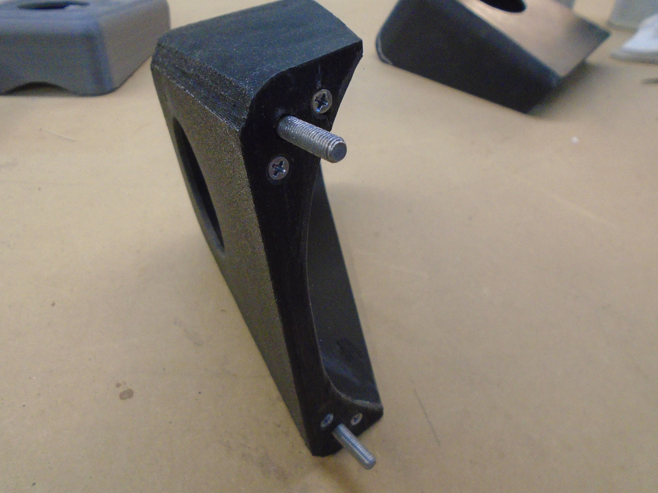
Even with a good plastic like ABS, 3D printed parts are still not that
strong, especially in thin sections like this. With much stress,
they tend to crack along the layers. To address this, I glued in
some solid 1/8" ABS reinforcing pieces. This made it pretty stout.
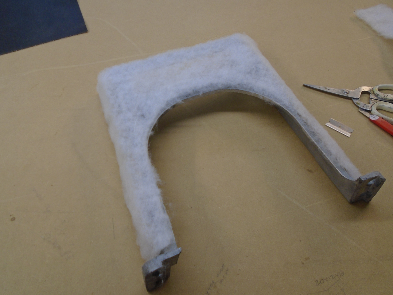
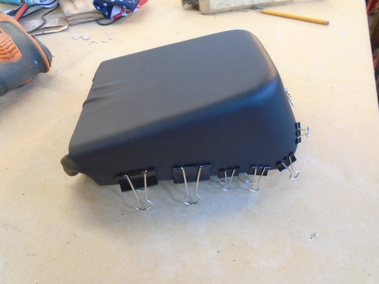
So, then it was time to make everything pretty. I covered the
support in black automotive vinyl, over a thin layer of Dacron batting
for touch appeal. The support's feet were the trickiest.
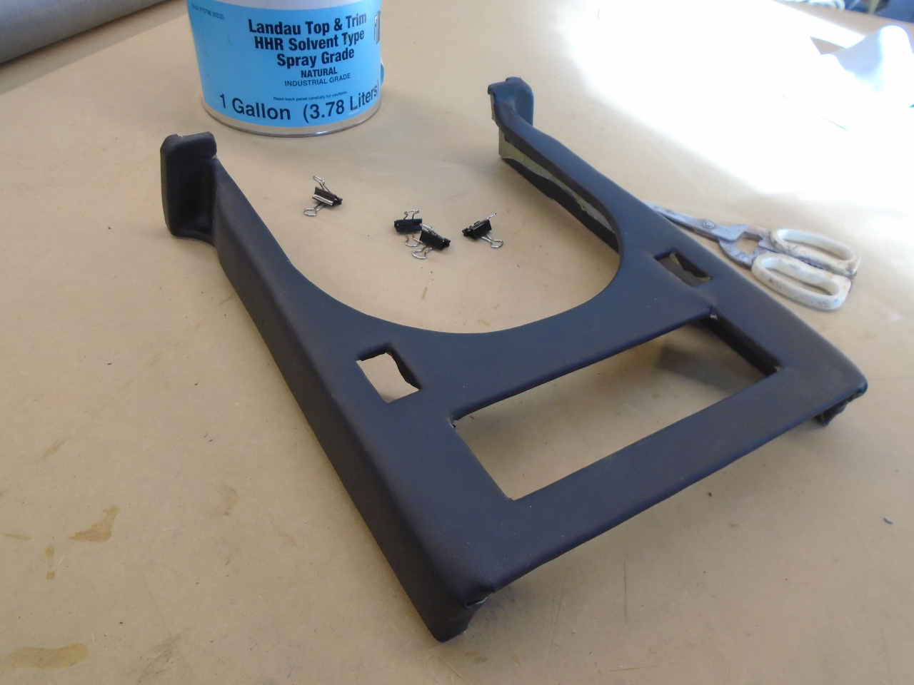
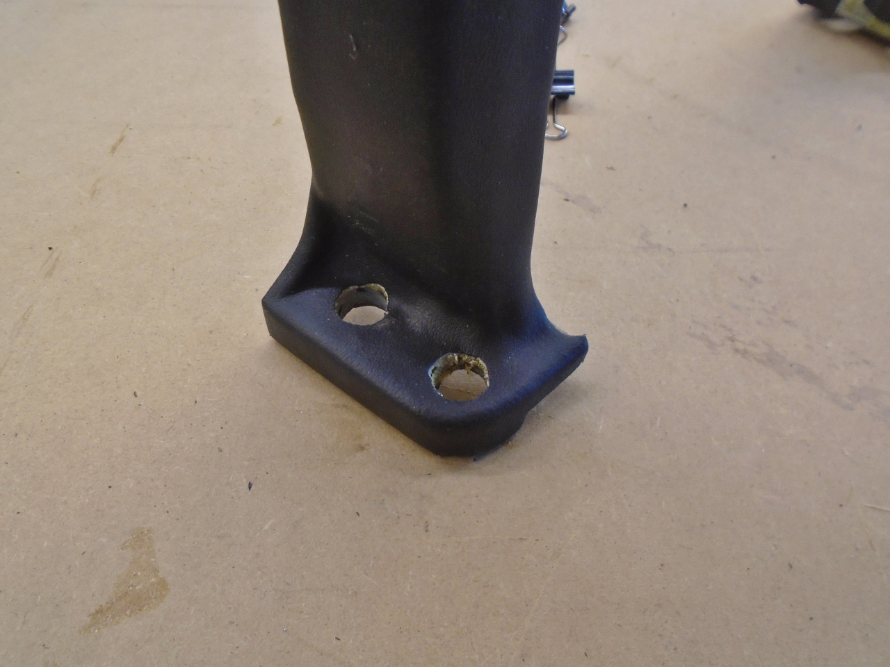
Looking more presentable.
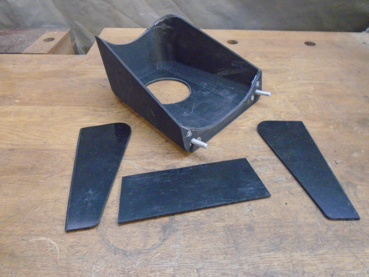
Before finalizing the plinth, I wanted to make sure it would still fit with carpet in place.
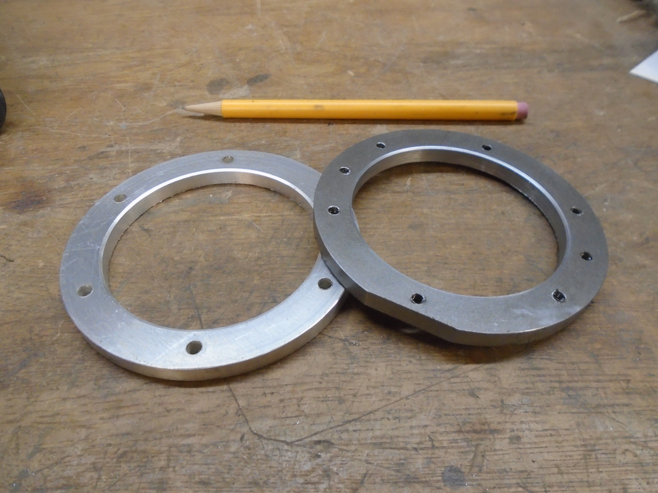
Since I can't use the original carpet-mounted shift boot, I had to come
up with something else to finish off where the shifter comes through the
plinth. I like those vinyl or leather boots with metal rings at
their base, so I made these. The one on the left is
aluminum, and will go at the base of the boot. The other one is
steel and will go on the underside the plinth to receive the fasteners
from the top ring.
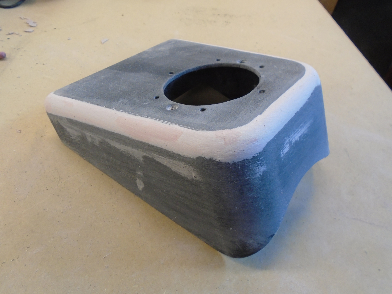
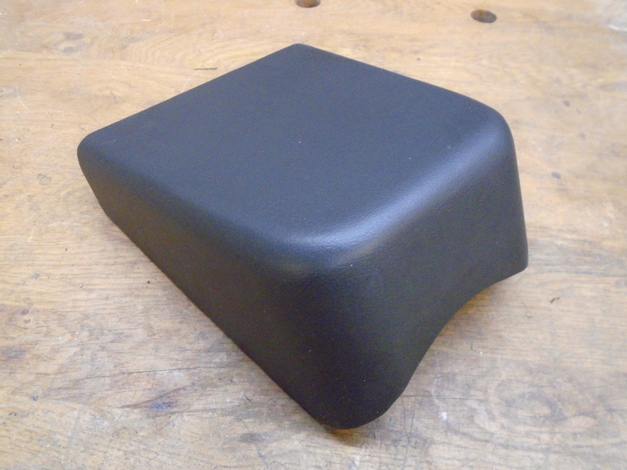
With that out of the way, I could pretty up the plinth. First, my
3D printer doesn't do a great job on radii that rise up from the print
bed, so I touched up those with some Bondo.
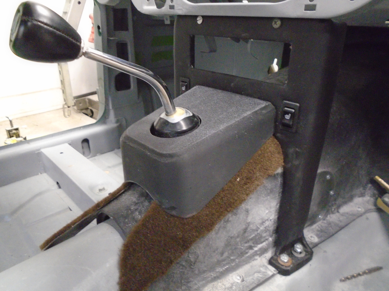
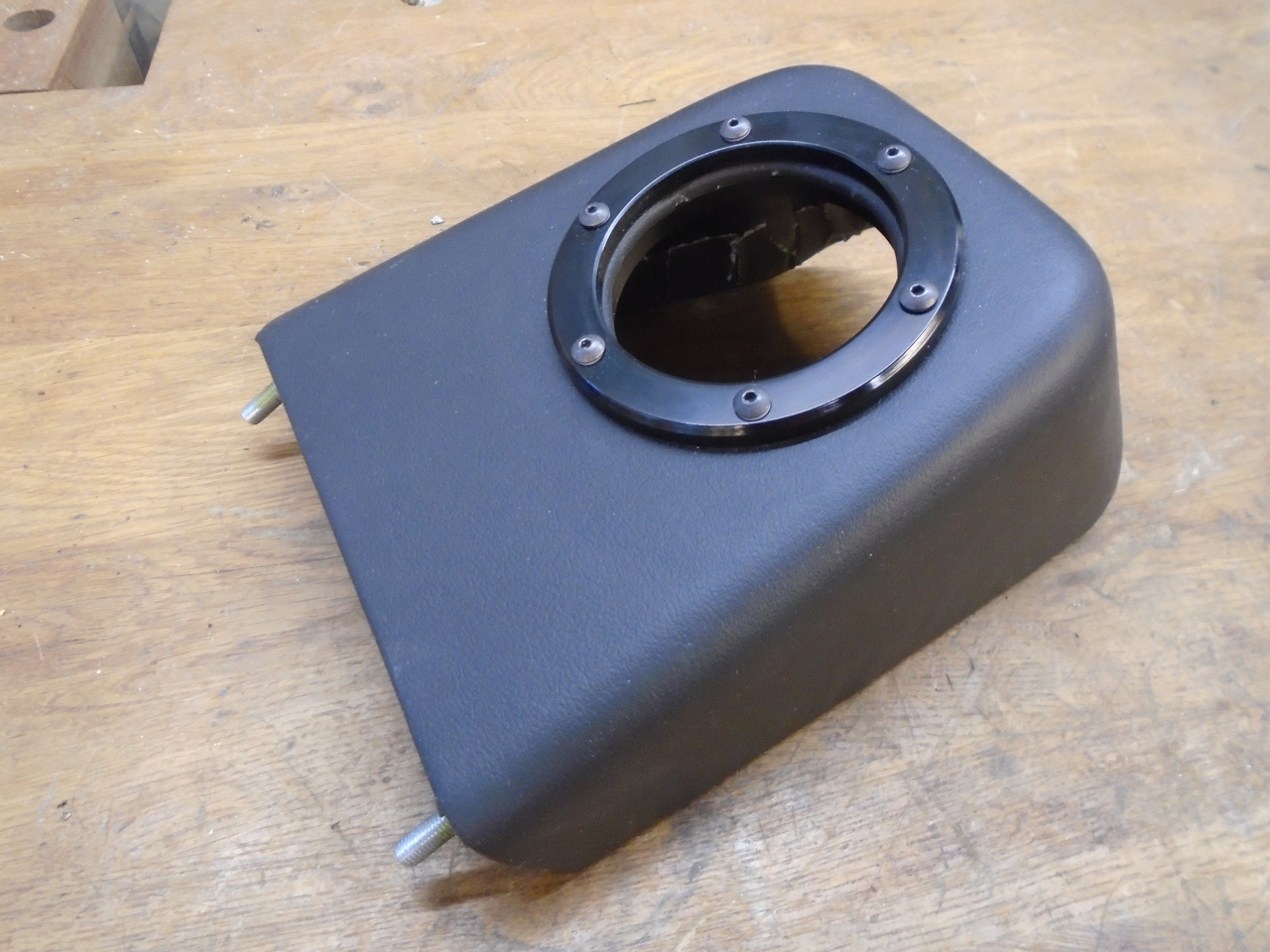
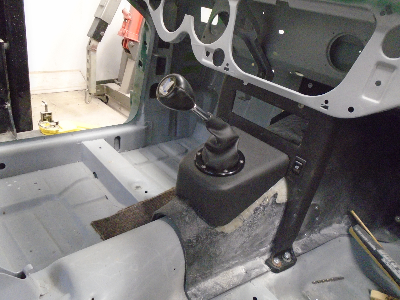
Then covered it with vinyl. With plinth's relatively deep shape, this was a stretch, pun intended.
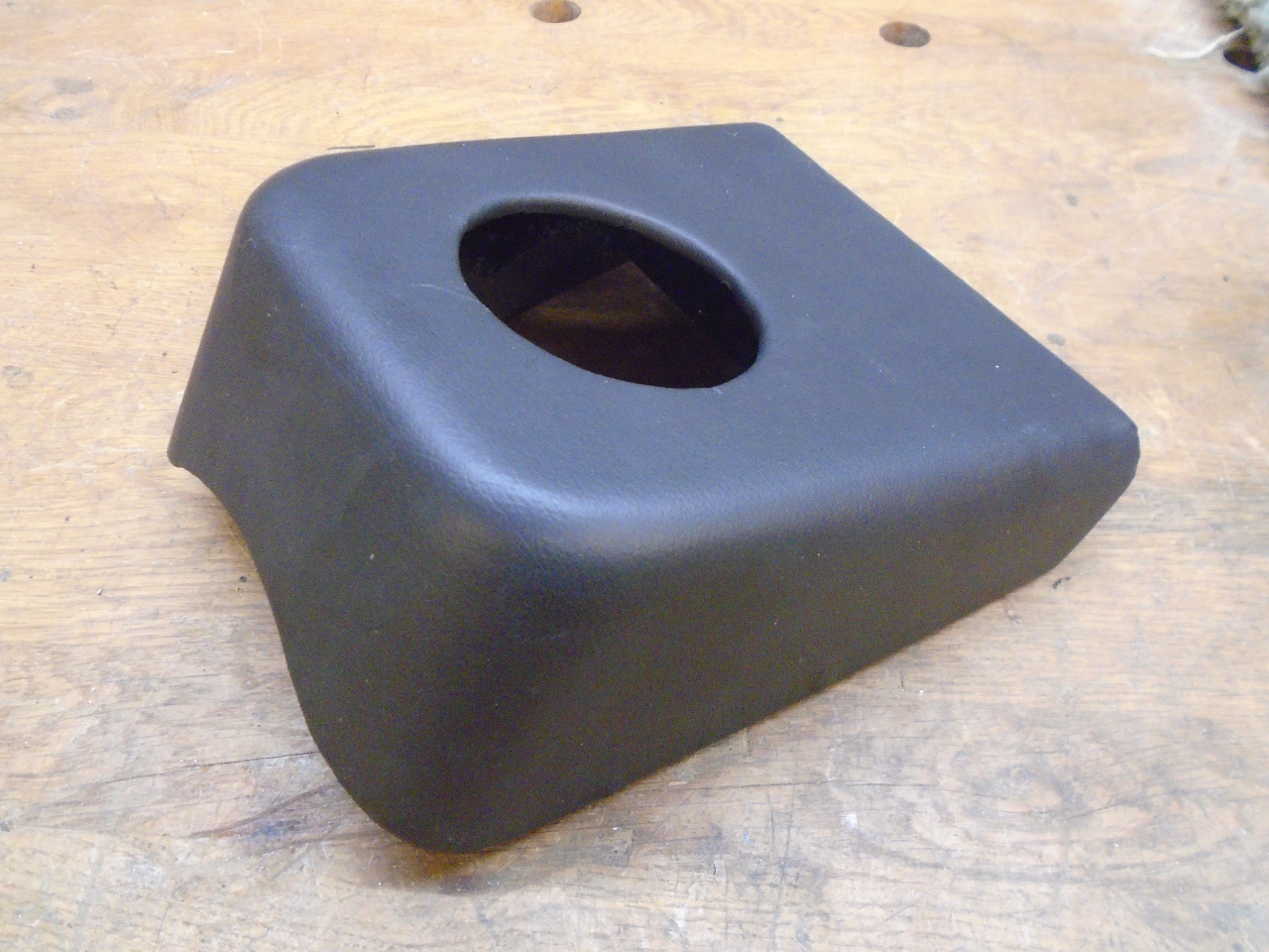
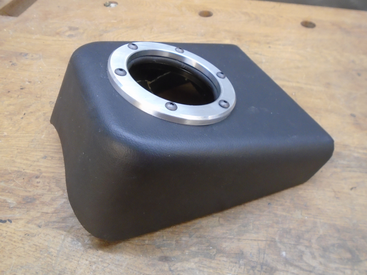
Applied the trim ring. The natural aluminum seemed a little stark to me, so I anodized it black.
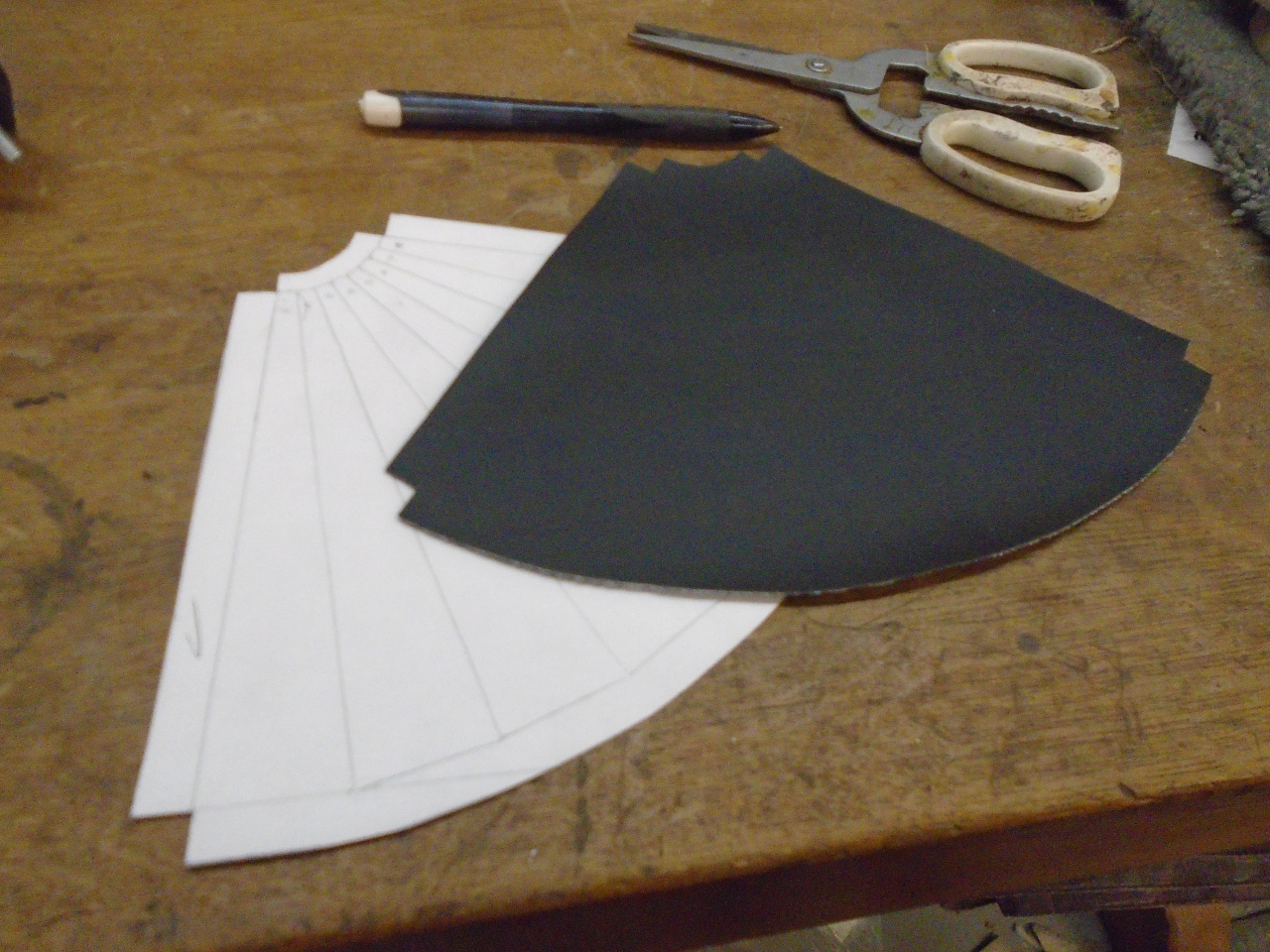
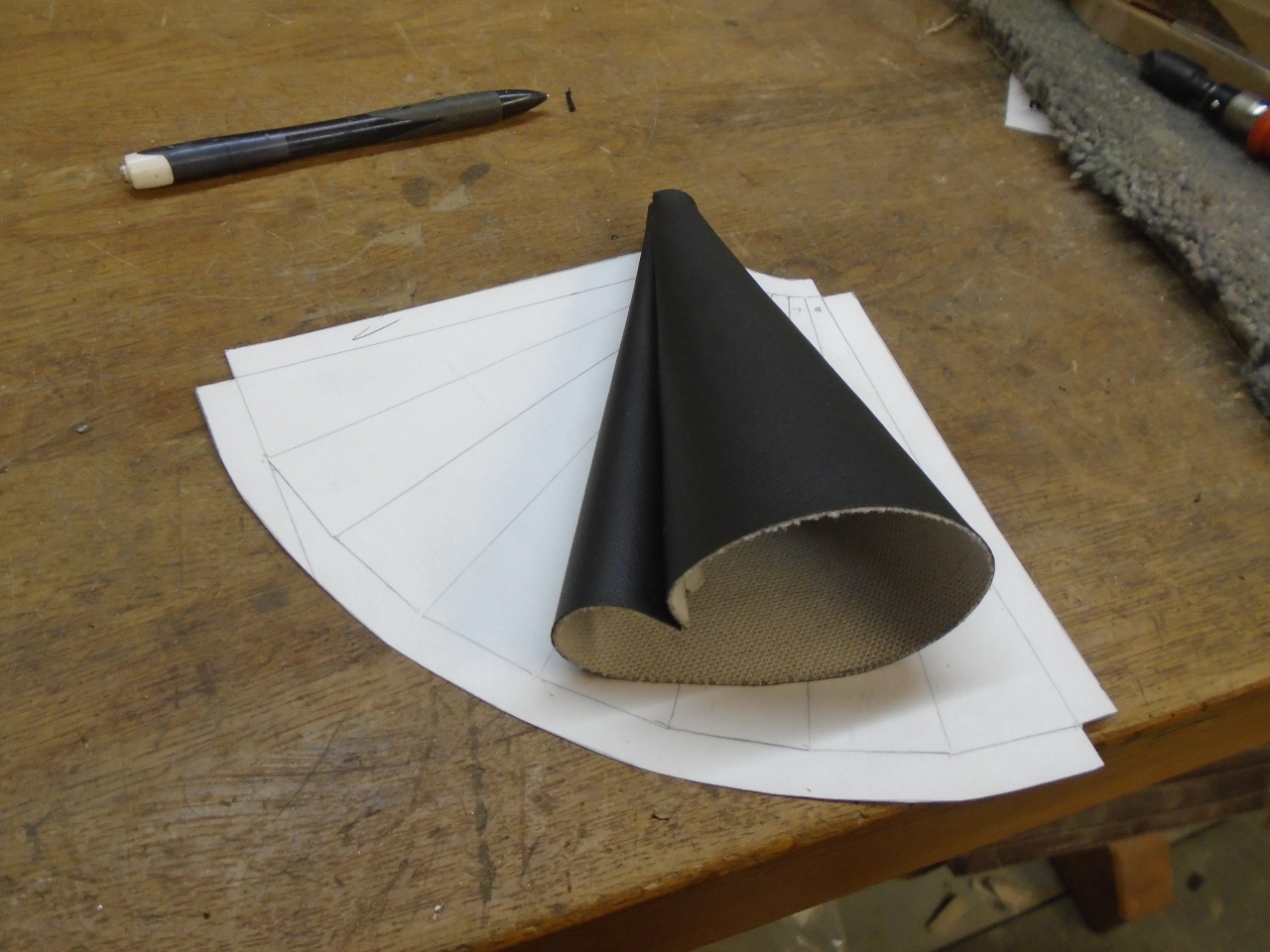
Now, for the boot itself. Maybe there is a universal boot out
there somewhere that would work, but I thought I might be able to make
one in the time it would take me to research it. Also, this way,
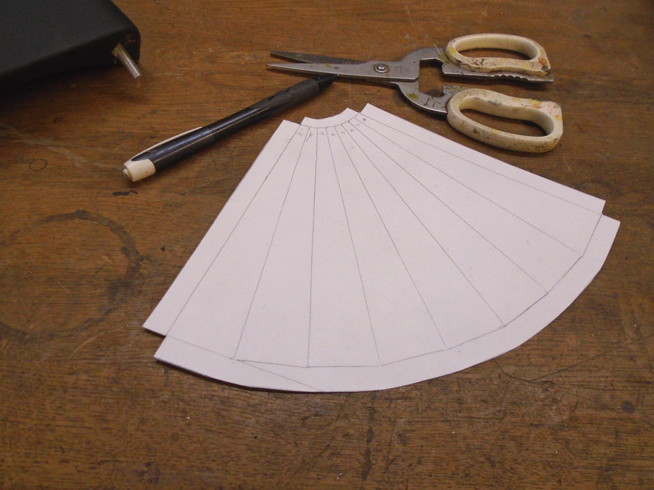
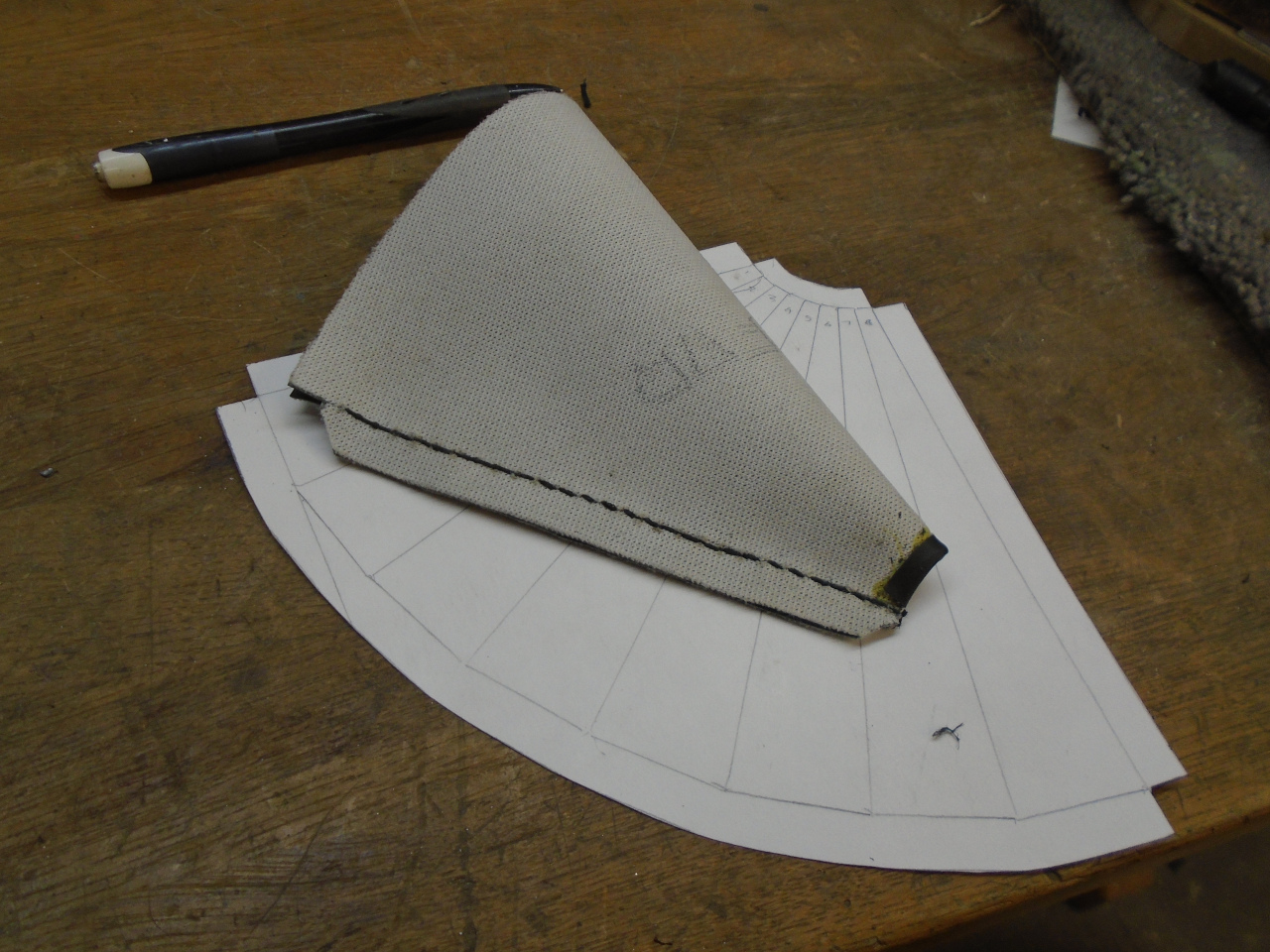
all of the vinyls will match. The boot is basically a transition
from a big circle to a little circle. For some reason, I still
remember how to generate transitions graphically from drafting class in
high school.
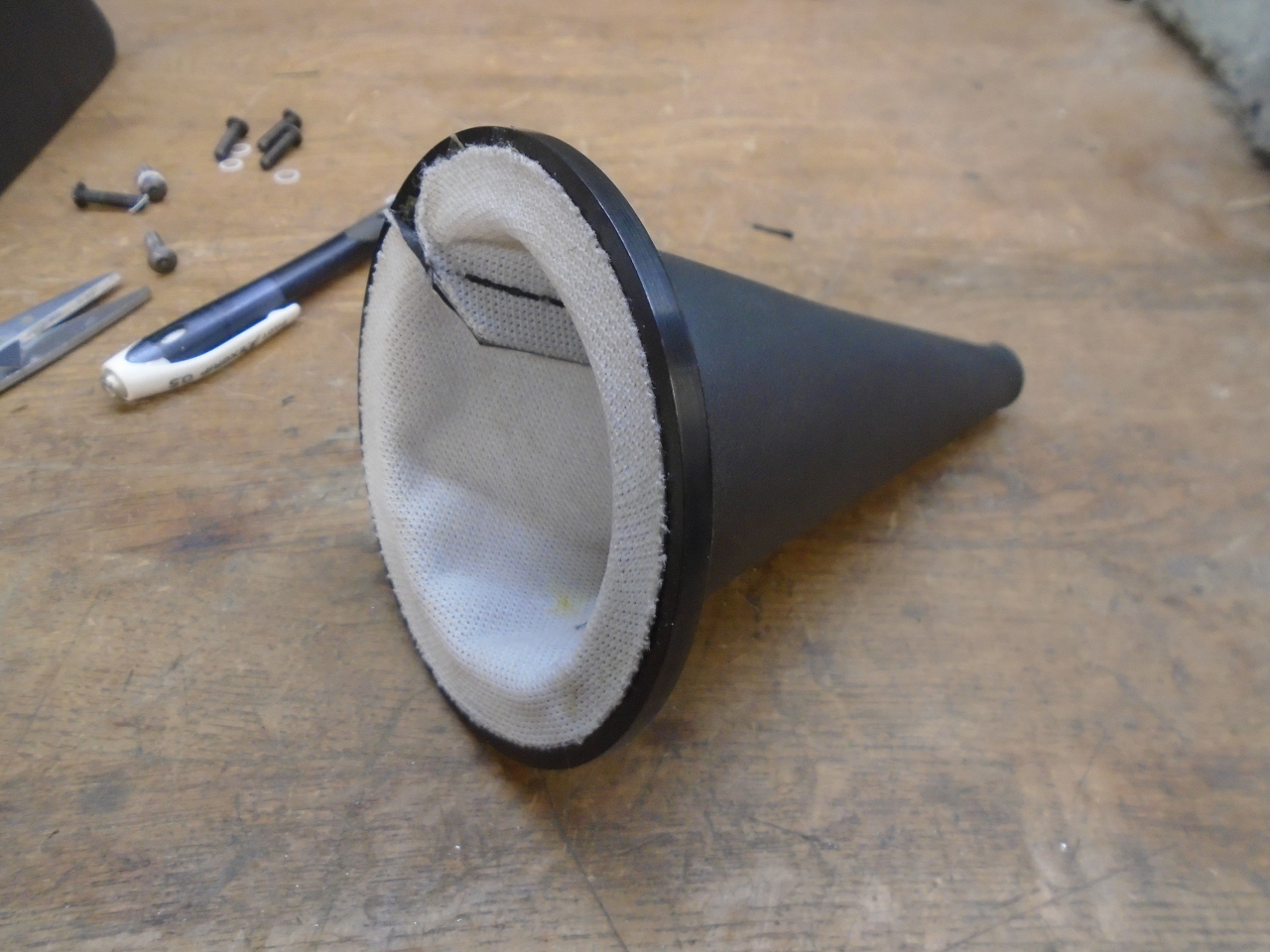
I had made a shallow relief on the underside of the aluminum
finish ring to receive the bottom circumference of the boot. It
was glued in.
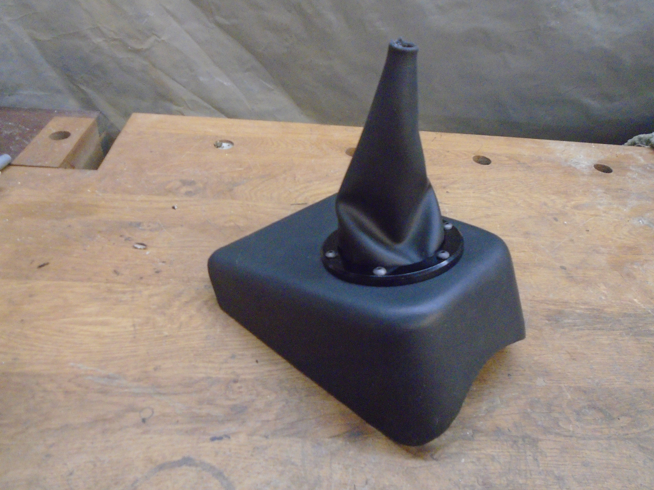
All put together:
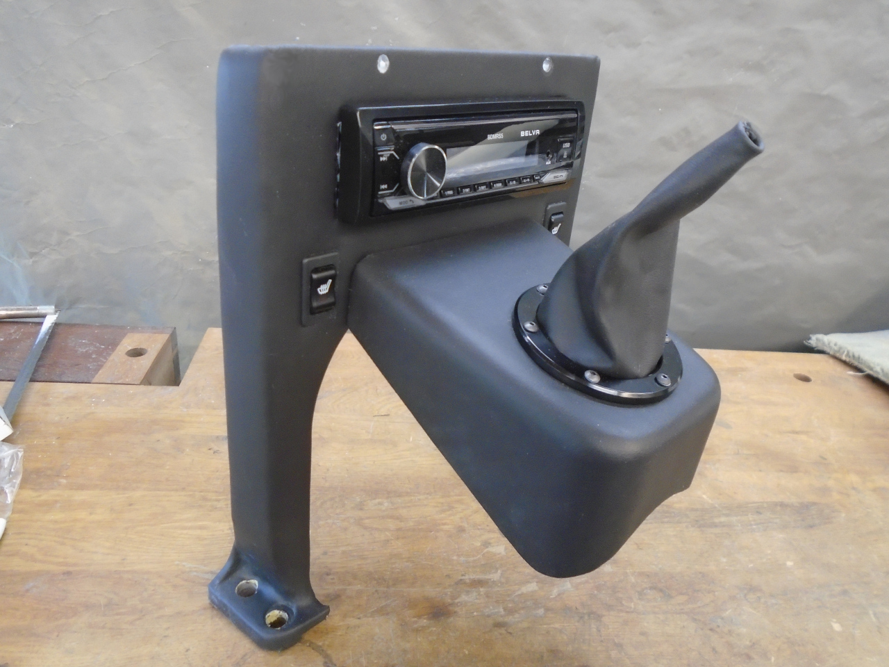
And a final reality check:
This was a fairly involved project. I had pretty much all of the
materials on hand, so the cost was close to zero, but it took
considerable pleasant shop time.
Comments to Ed at elhollin1@yahoo.com
To my other GT6 pages