To my other GT6 pages
August 17, 2019
Steering Rack & Pinion
I
think just about all Triumph cars of this era sported rack and pinion
steering. This kind of steering provides very responsive control
with good feedback from the road to the steering wheel.
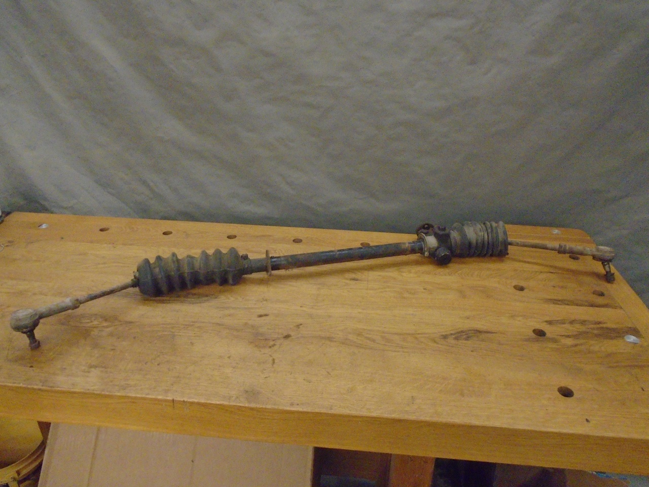
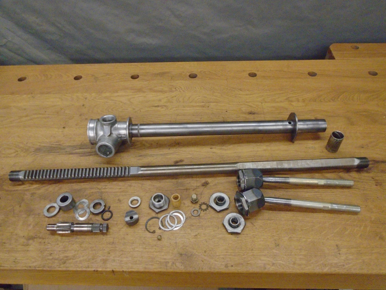
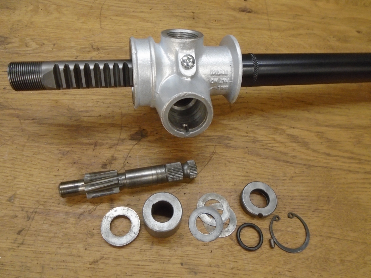
My
steering sassembly was rusty, dirty and greasy, but it seemed to be
working OK. I decided to take it apart and at least refresh the
50 year old lubrication. I also found a few small things I could
improve.
Under
the tired bellows boots are the inner ball joints for the tie rods.
I was actually happy to find a lot of grease in there. It
means that the joint had not lost lubrication.
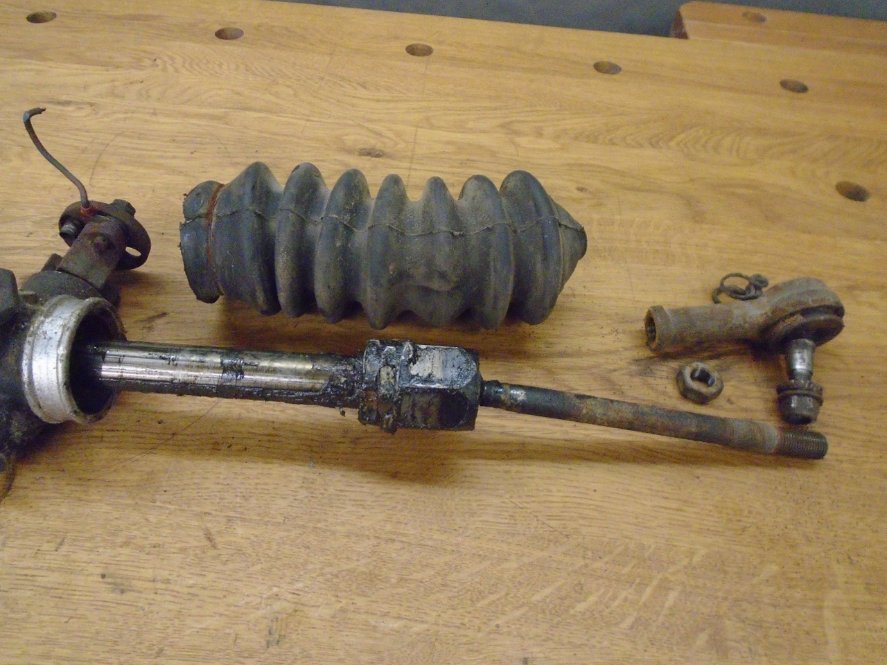
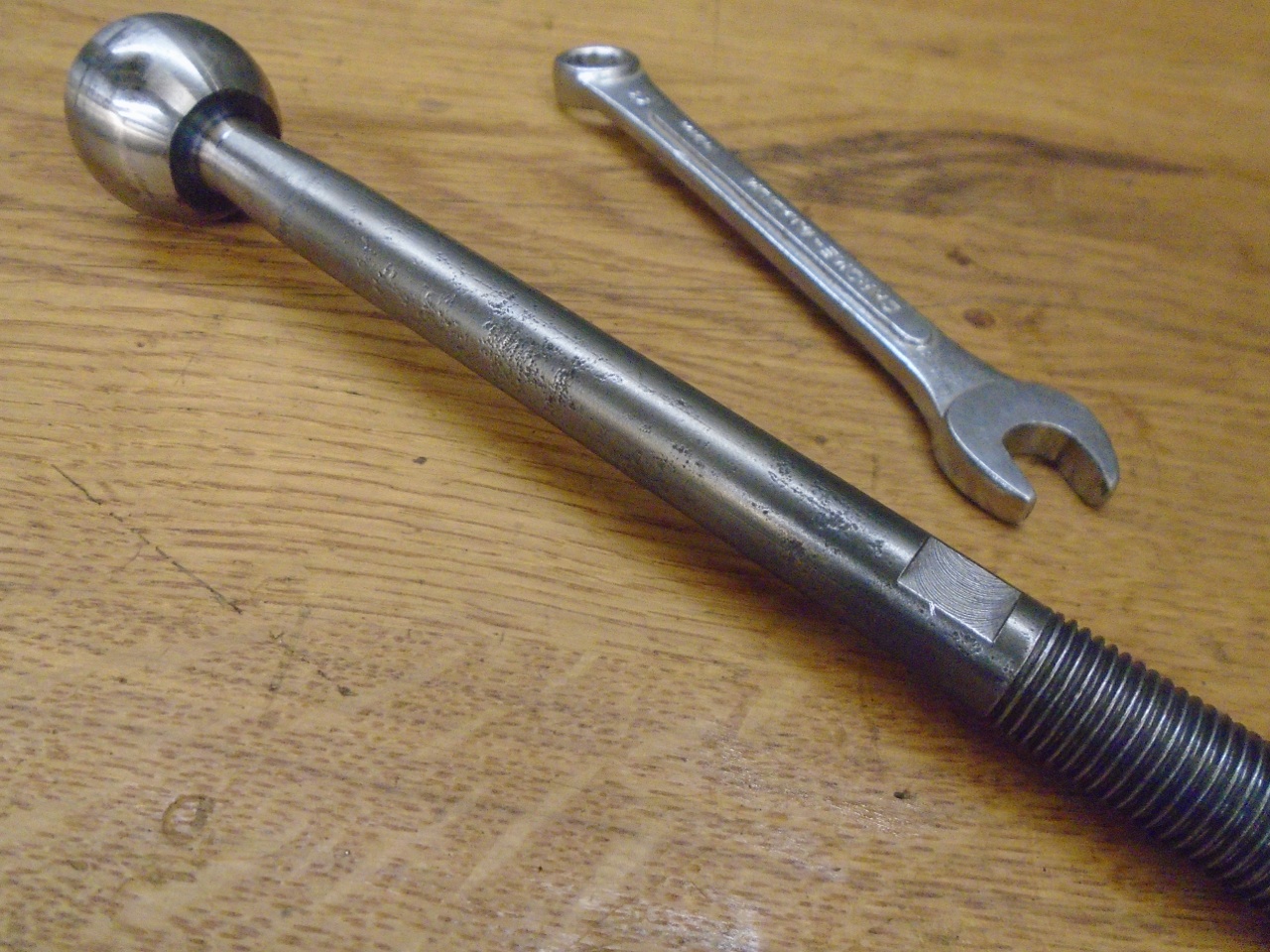
Here is one place where
I made what I consider a small improvement. When adjusting toe-in
on thece cars, the tie rod ends have to be screwed in or out on the tie
rod. The problem is, if the threads are a little tight in the rod
end, turning it just rotates the tie rod. The usual remedy is a
pair of Vice Grips on the tie rod. I was looking for something a
little more civilized than Vice Grips. I had seen tie rods
somewhere that had flats milled into them so a wrench could hold them.
So that's what I did. Milled flats for a 3/8" wrench.
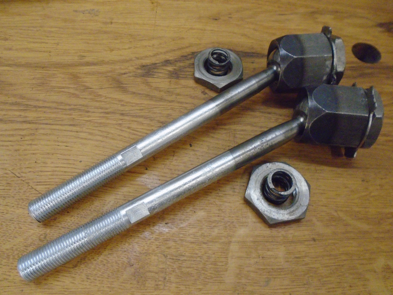
Also zinc plated the parts of the rods that are exposed to the elements.
Then cleaned up the rest of the parts for a good inspection.
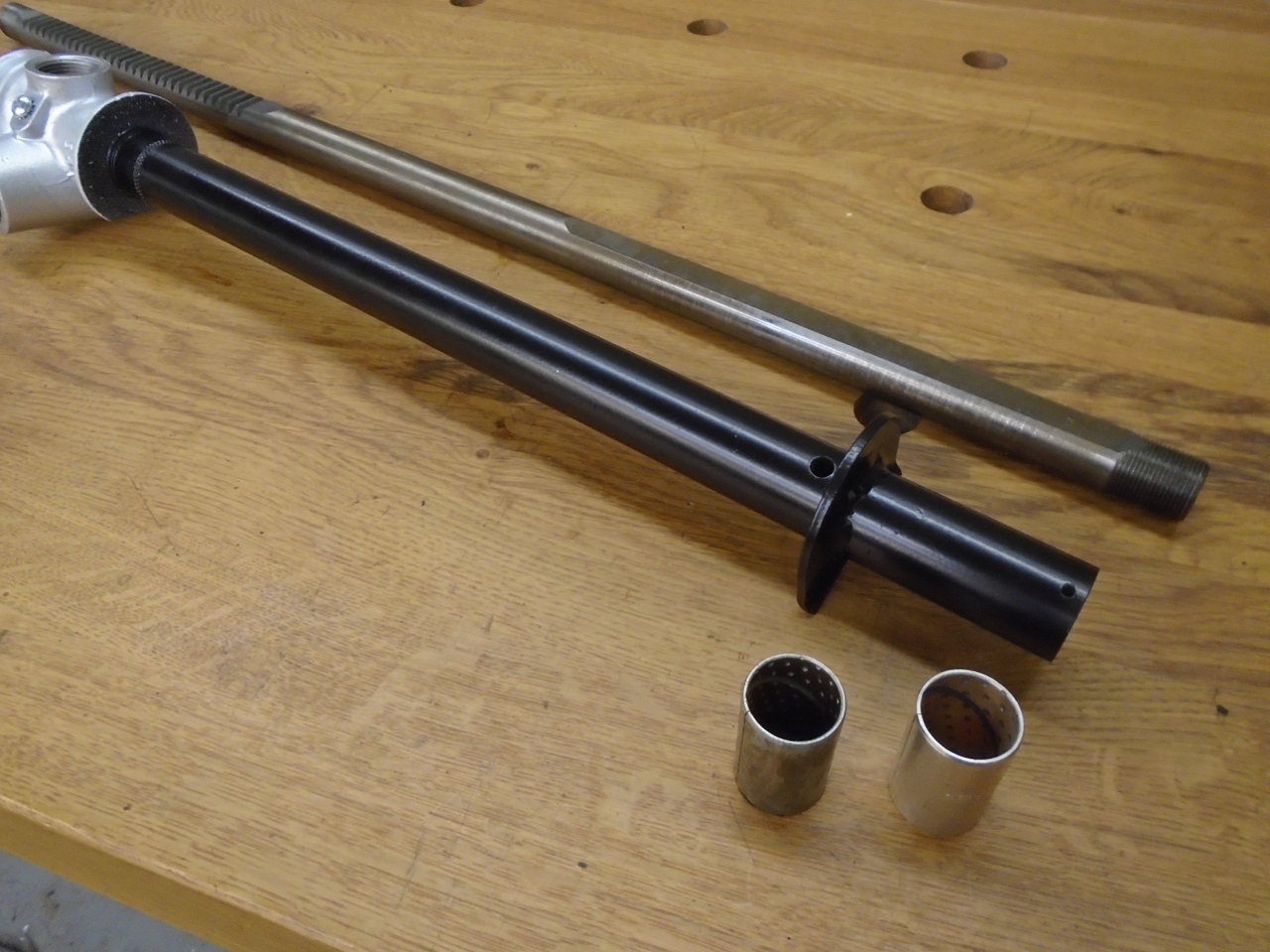
Powder
coated the steel rack tube. I bought a new end bush, but the
original was a better fit on the rack, so I put it back in.
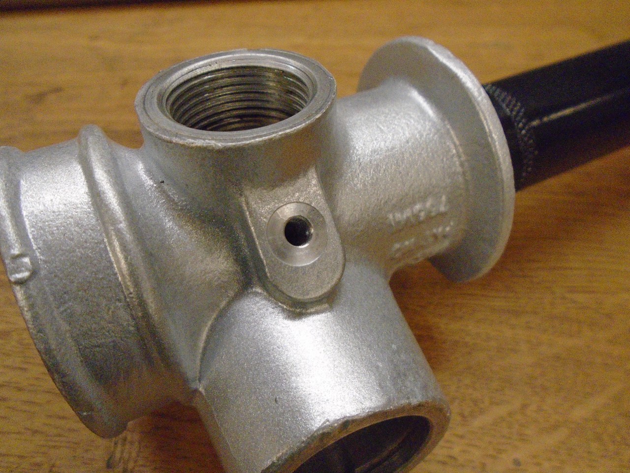
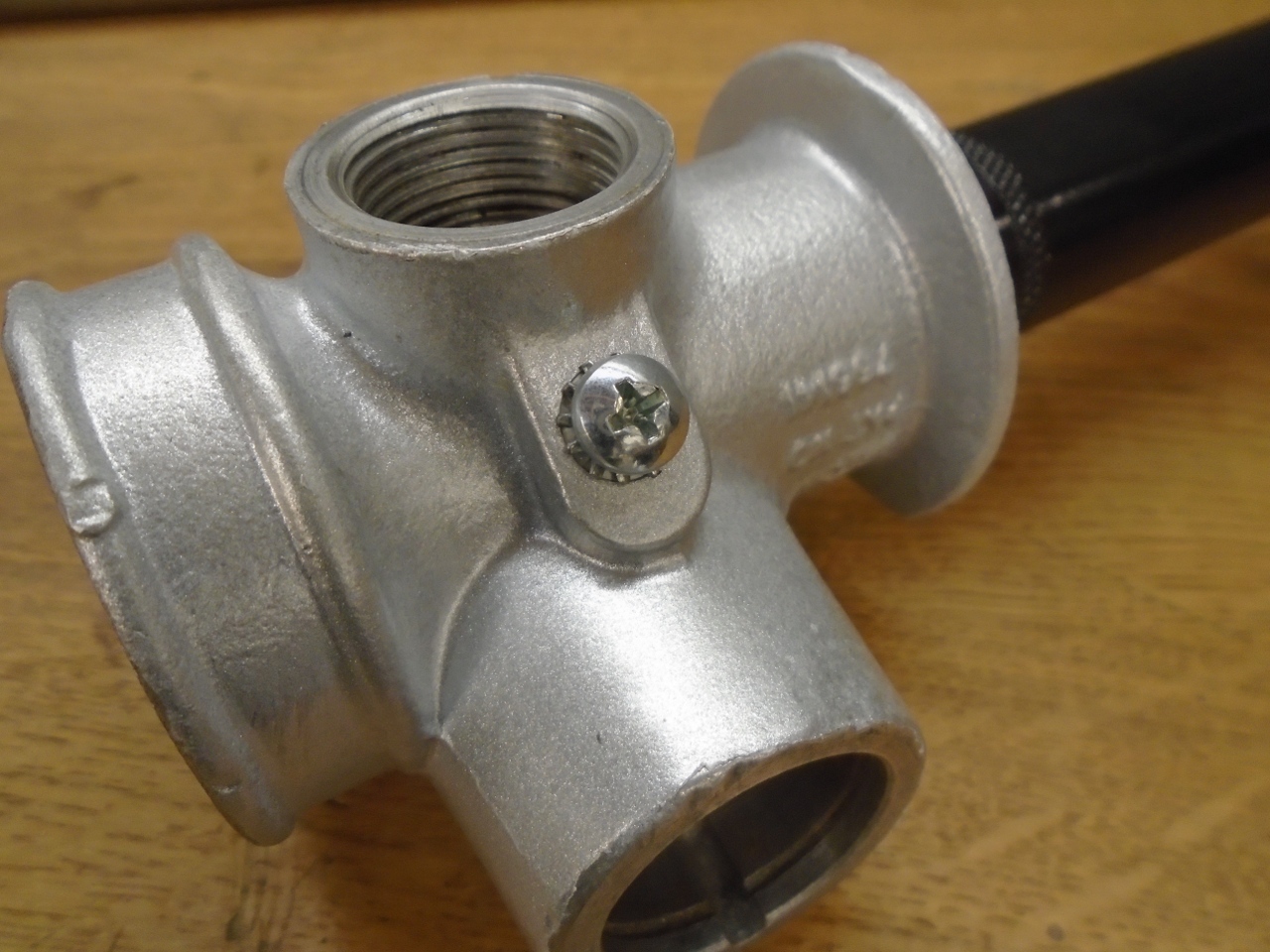
I remembered
how Triumph liked to ground the horn switch--with a wire terminal under
a plug in the rack lube hole. Factory instructions for greasing
the rack were to remove the plug, replace it with a grease zerk, pump
some grease, and then remove the zerk and replace the plug and ground
wire. That has always seemed a little more convoluted than
necessary to me. I found a nice place for an explicit ground
screw, then drilled a hole and tapped it. There is quite a bit of
meat there, so the hole is blind and doesn't communicate to the inside
of the rack housing. This will allow a full-time zerk on the
steering box.
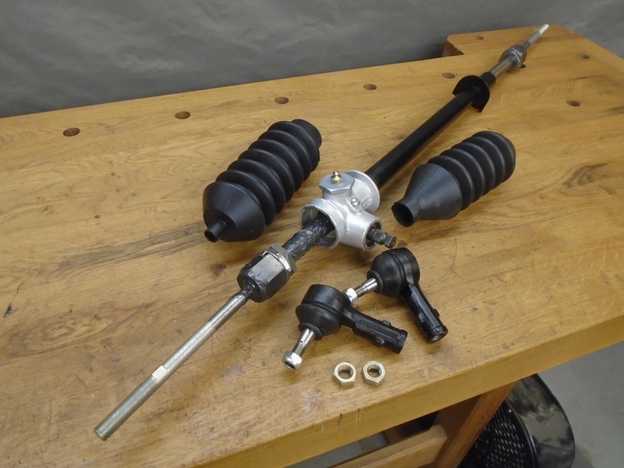
I
lubed up the rack and installed it in the tube. It was then time
for the pinion and associated parts. Pinion end play is adjusted
with shims. A dry fit showed that the original shims still
yielded smooth operation with undetectable play (undetectable by hand,
that is). The only replaced part was the O ring that seals the
pinion shaft.
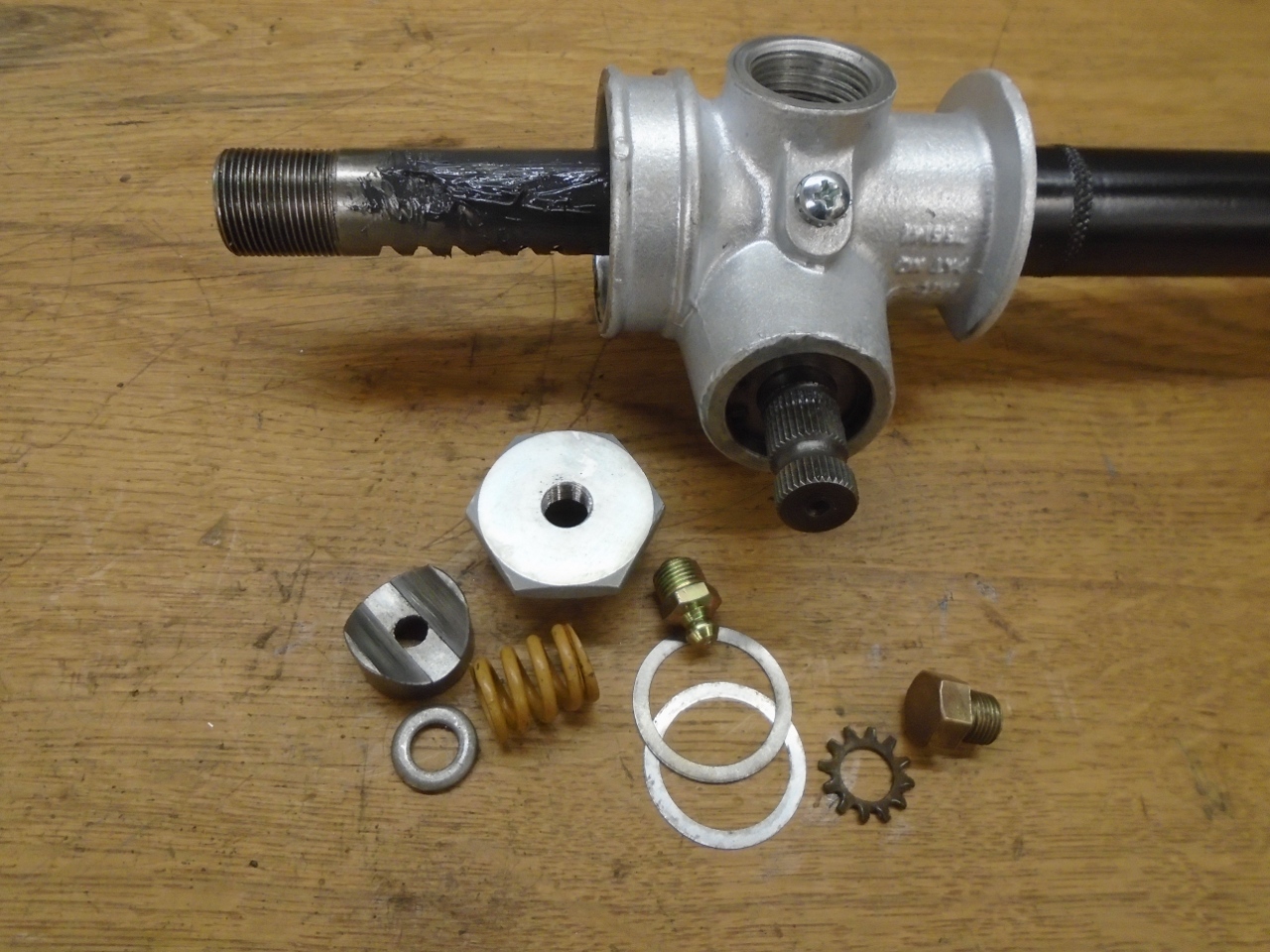
The
remaining pieces that go in the rack housing are those for the damper.
The damper "stiffens" the steering by a controlled amout to give
it a more positive feel. It consists basically of a spring loaded
wiper that bears on the rack just opposite the pinion gear.
Again, shims adjust the spring pressure on the rack. The brass plug is now excess.
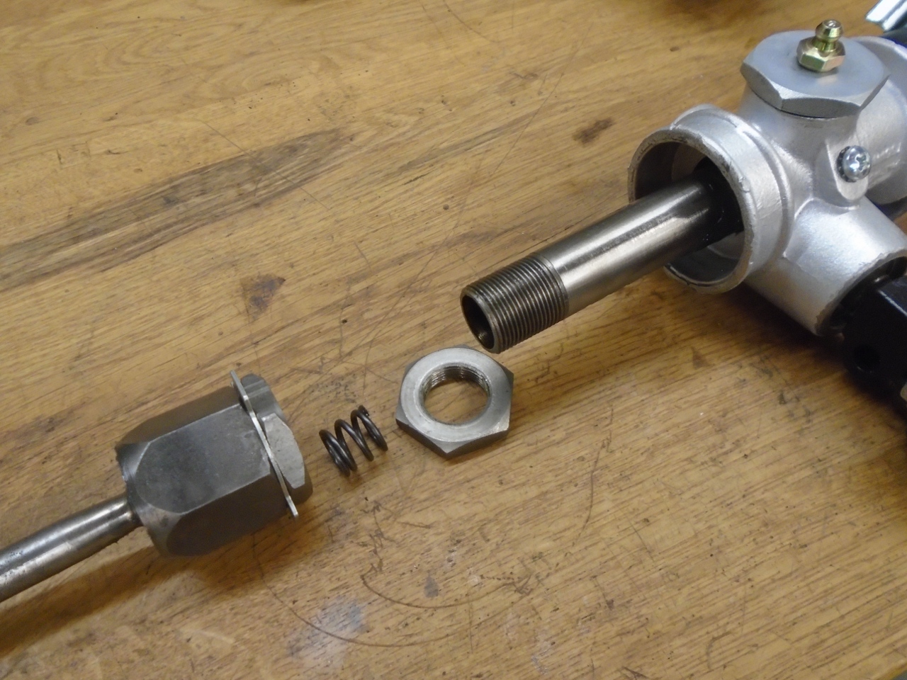
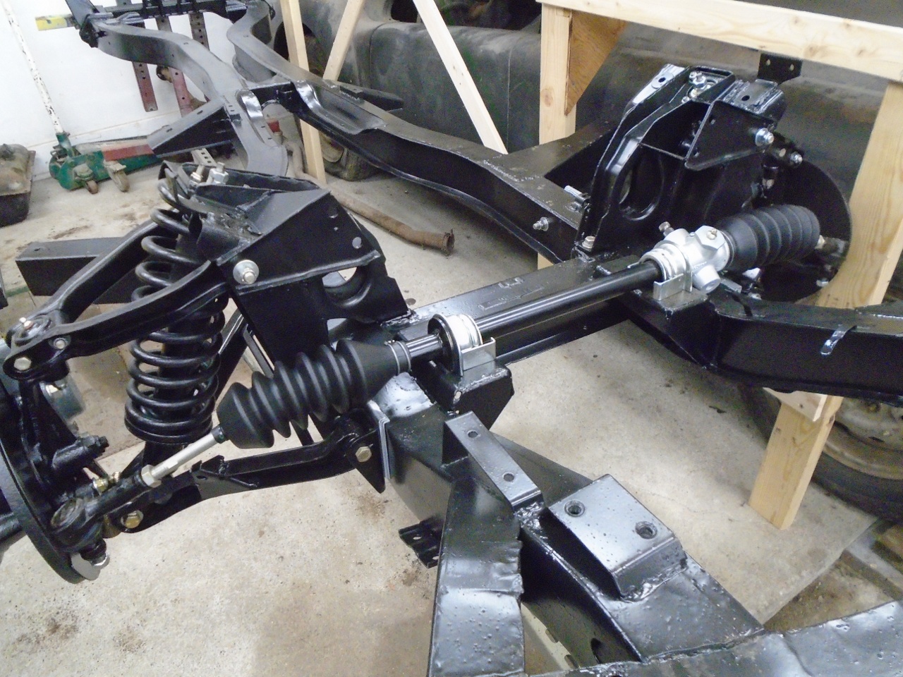
With
the rack and pinion buttoned up in their housing, it was time to attend
to the inner ball joints. The large nut and the smaller cup form
a spherical space that the ball end of the tie rod is captured in.
A cap is screwed in to hold it all together. Shims under
the head of the cap adjust pressure on the cup to control play. I
had to remove the thinnest shim from one of the joints to get the firm
but smooth action I was looking for. This probably was due to
slight wear, but the tab washer also has an effect on the necessary
shims, and that is not a precision part. The other joint went
back together the way it came apart. After the fit was good, they
came apart again, got loaded with grease, and reassembled.
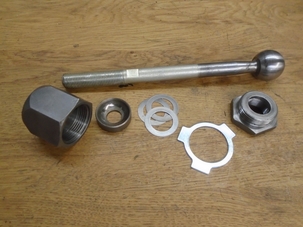
The inner ball joints screw onto the ends of the rack with a stiff spring to bias what little play there might be in the joints.
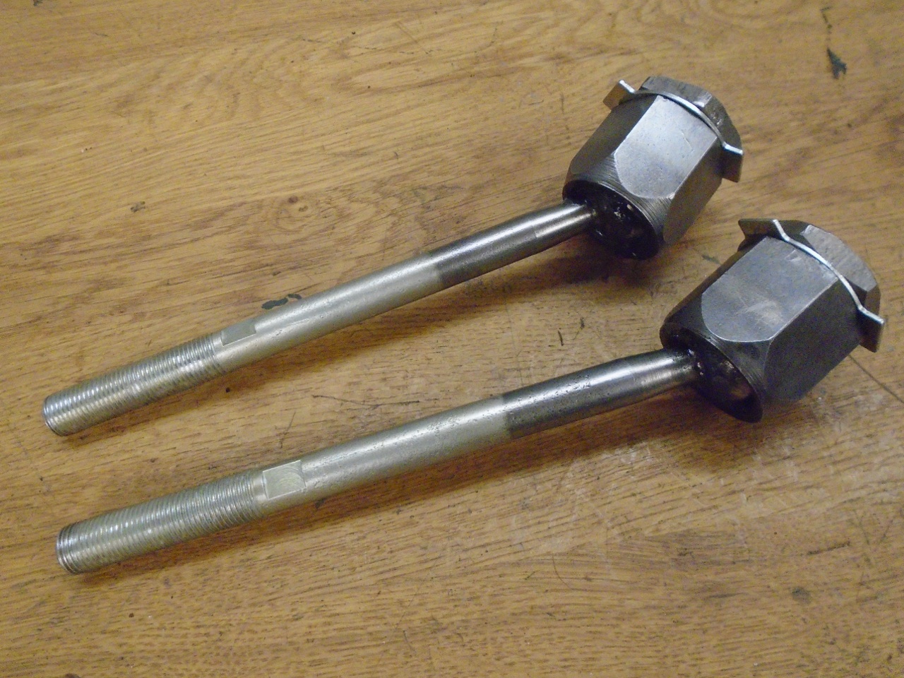
The boots can be a bit of a wrestling match to install, but they finally went home. Also got new tie rod ends.
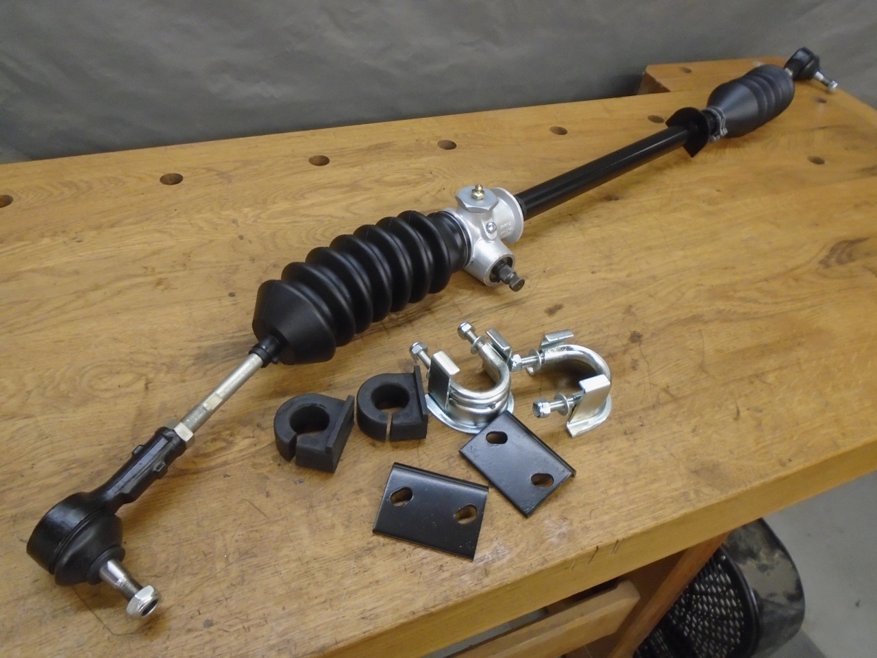
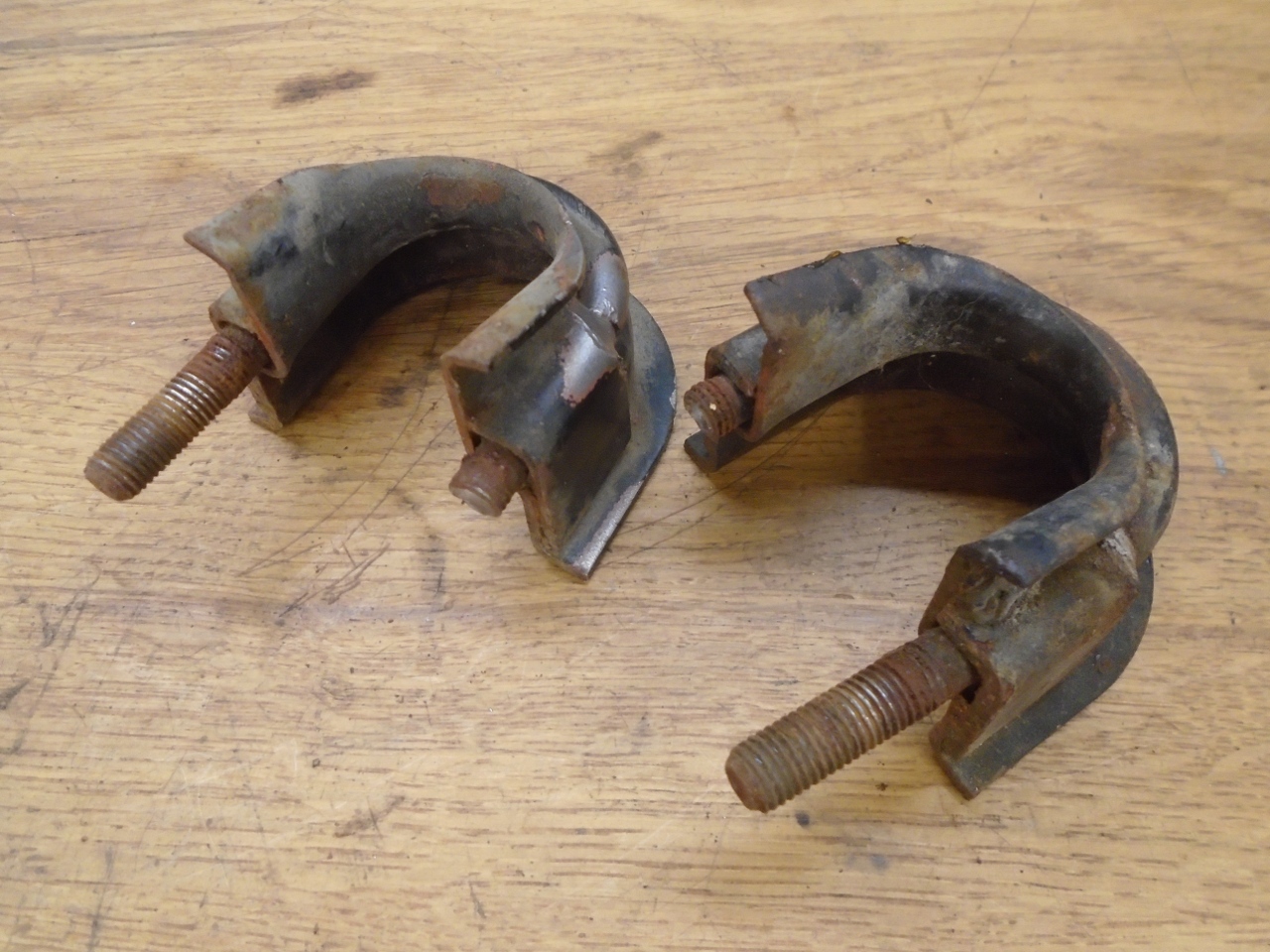
The new U bolt mounts were to replace the ones that didn't come along quietly.
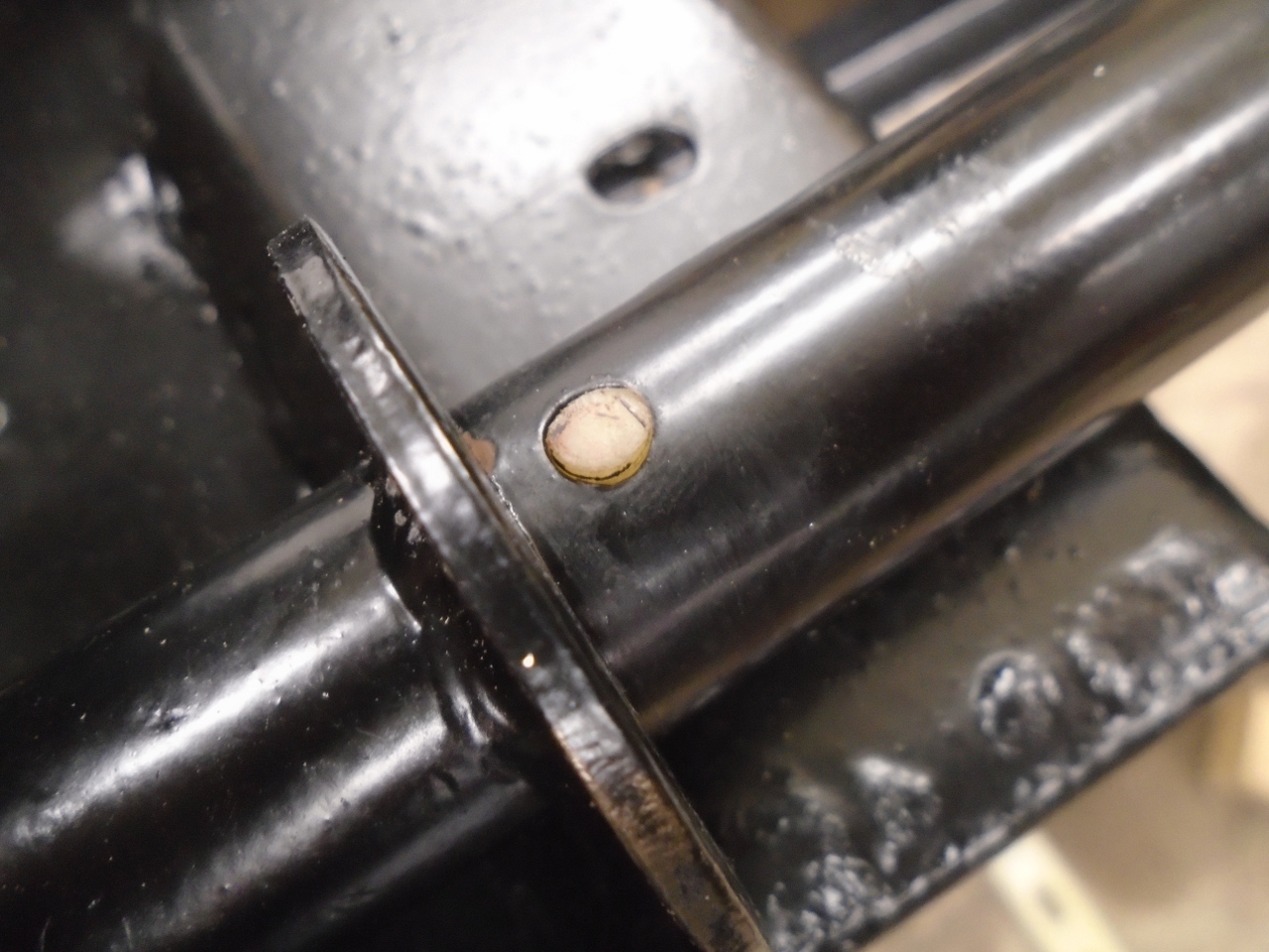
Just
in time, I remembered this little nylon button. It bears on the
rack under pressure form the right hand rubber steering mount. I
don't really know what it's for, but my TR6 had one, too.
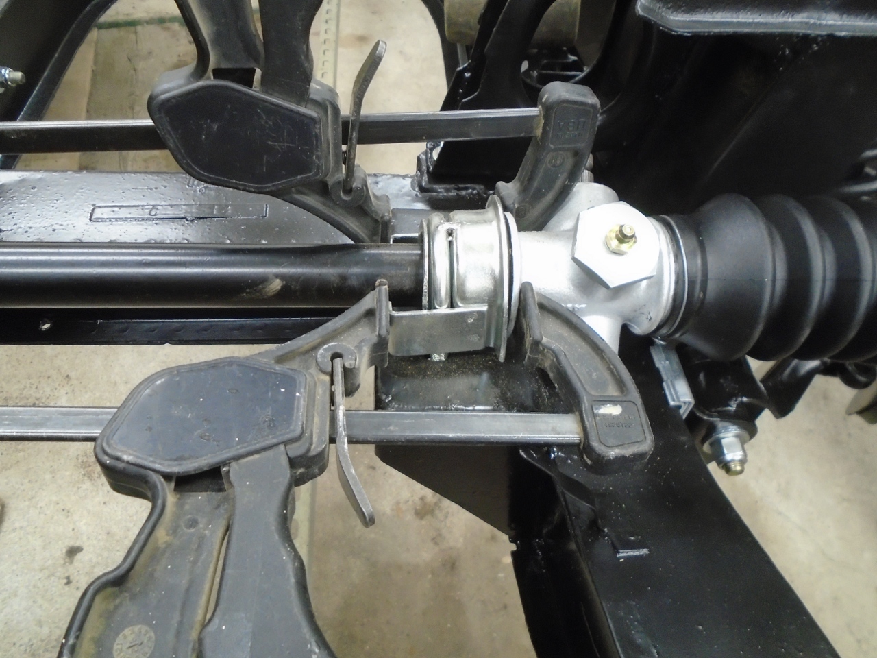
To
prevent the rack and pinion assembly from shifting, the rubber mounts
need to be tightly captured between the U bolt brackets and the flanges
on the rack tube.
This job completes the front end of the frame, except for the anti-roll bar, which I can't seem to find.
On to the rear!
Comments to Ed at elhollin1@yahoo.com
To my other GT6 pages