To my other GT6
pages.
October 1, 2020
Remounting the Body
I waffled quite a bit about whether to paint the body while it
was up on the rotisserie, or to mount the body on the frame and
paint it later. One huge problem is that I haven't settled
on a color yet, and don't really want to be rushed in that
decision. Plus, I haven't even started the bonnet yet, and
it would make sense to paint them both when I set up the paint
booth. So, for these and a few other reasons, I decided to
remount the body to the chassis now.
With that decision made, I considered all the prep work to do.
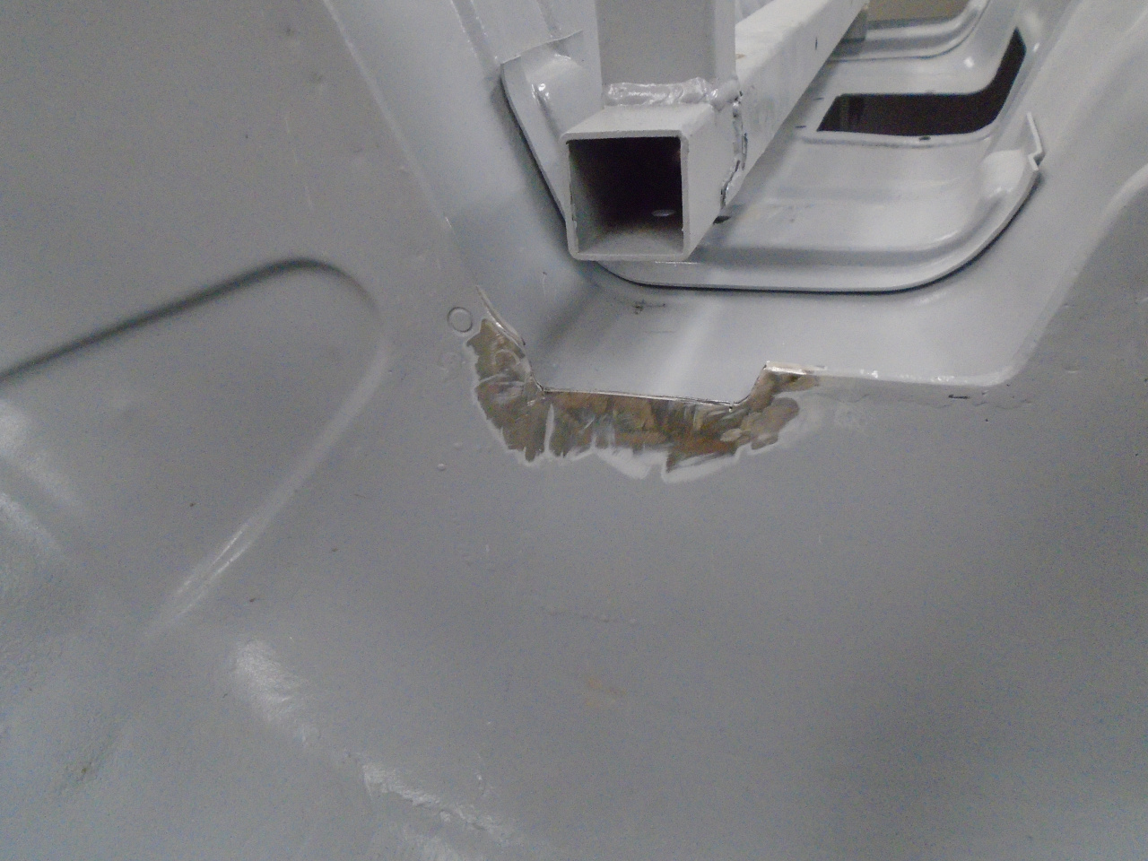
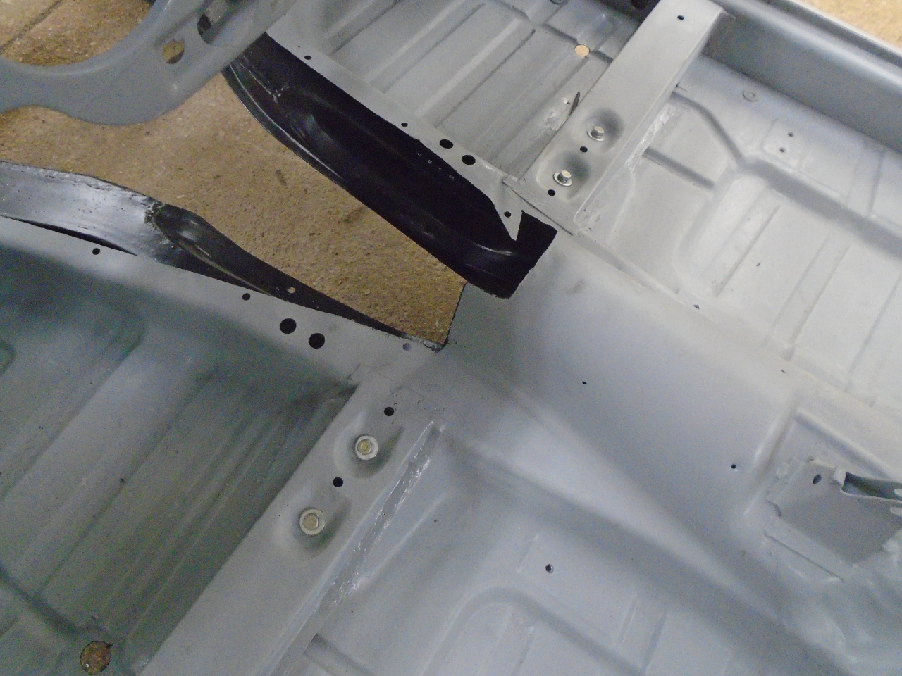
First, in an uncharacteristic instance of forethought, I
remembered that there was a small surgery that needed to be done
to the wheel well to accommodate the damper
extension brackets. The body is upside down in this
pic. That edge was welded closed before patching the epoxy
primer.
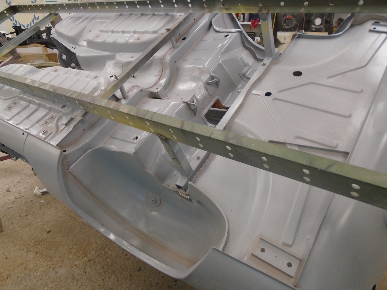
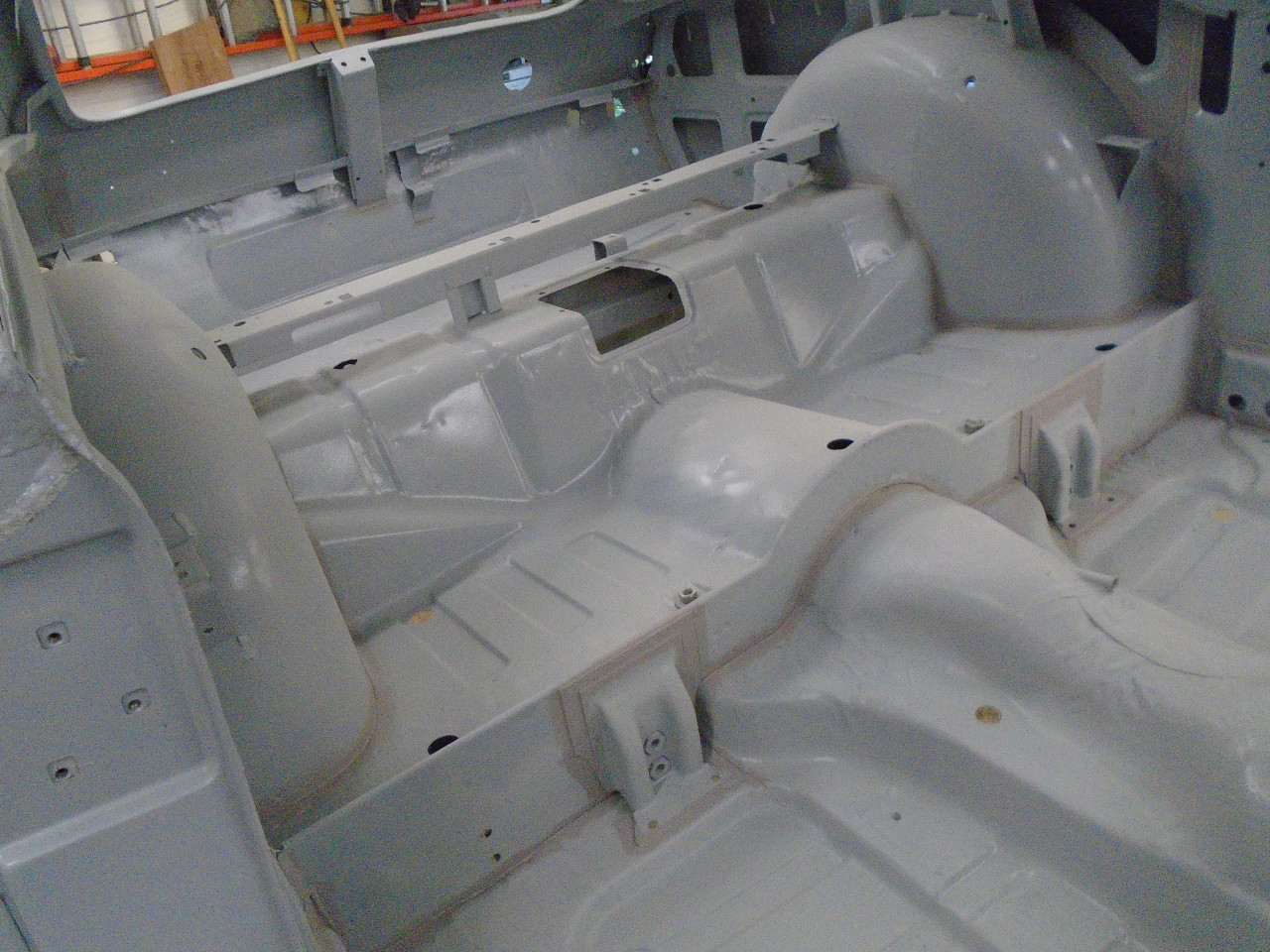
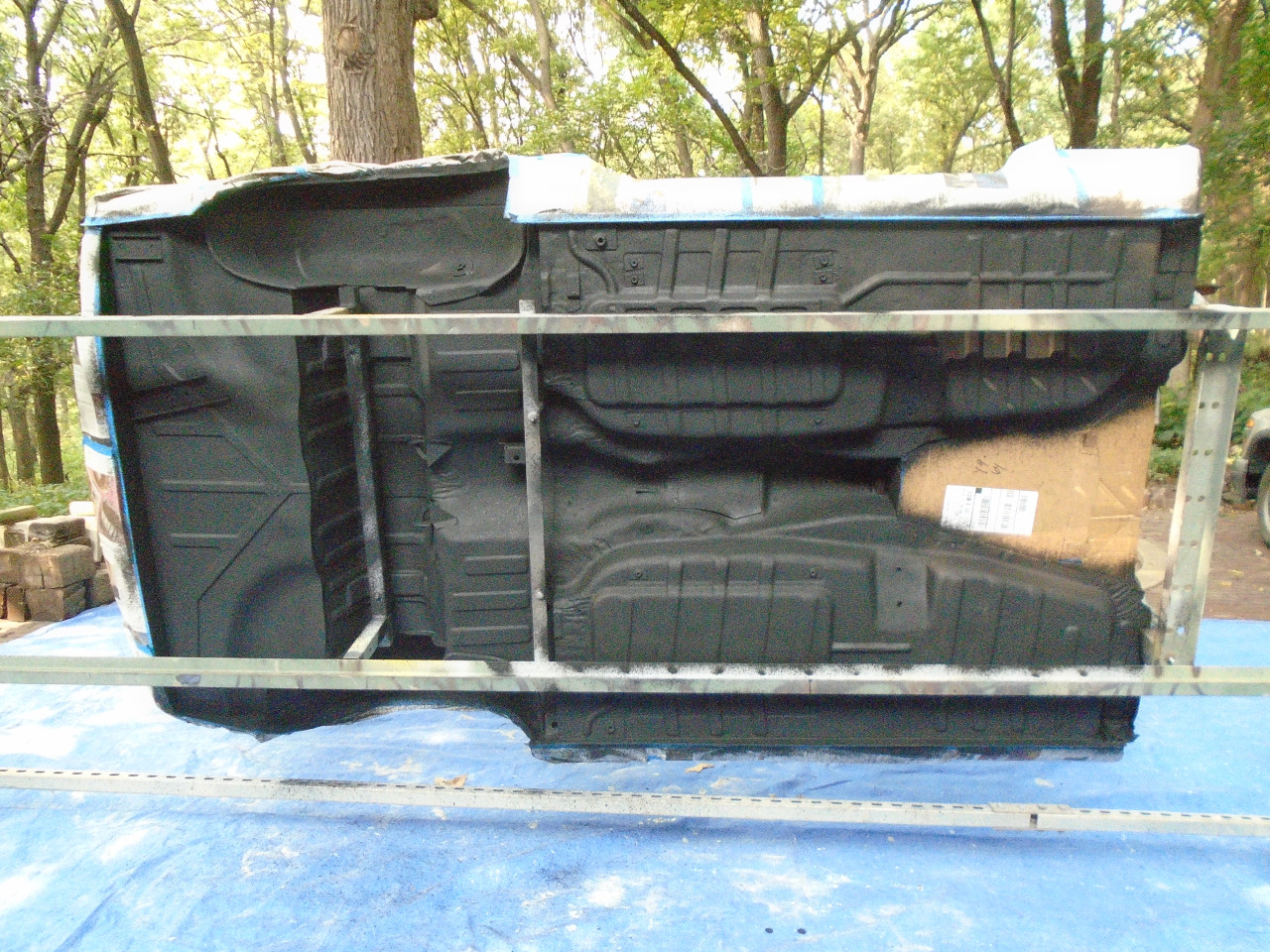
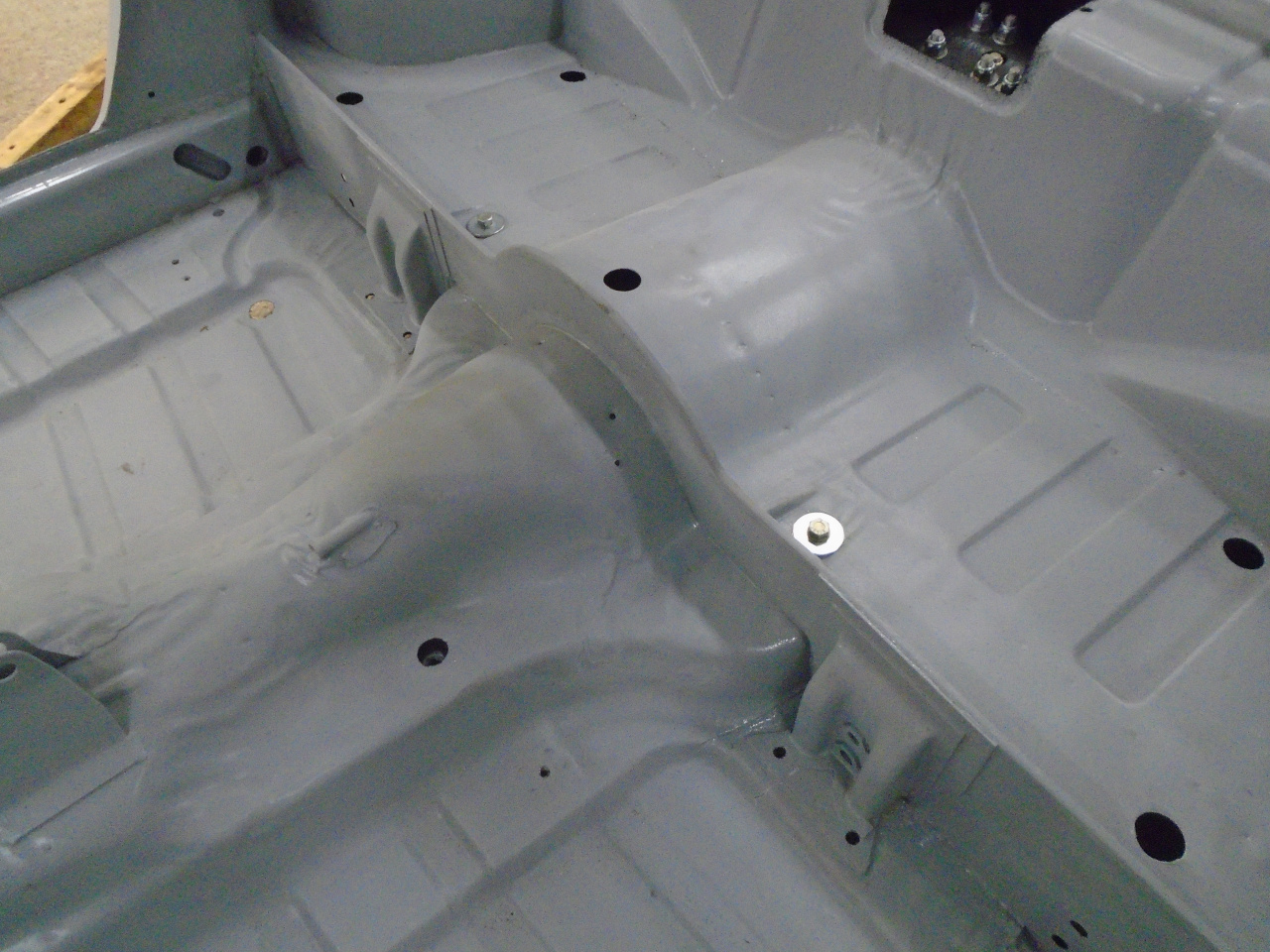
Then a 3M brushable seam sealer was applied to all the joints I
could find, both top and bottom. The sealer is gray, so
it's a little hard to see against the gray primer.
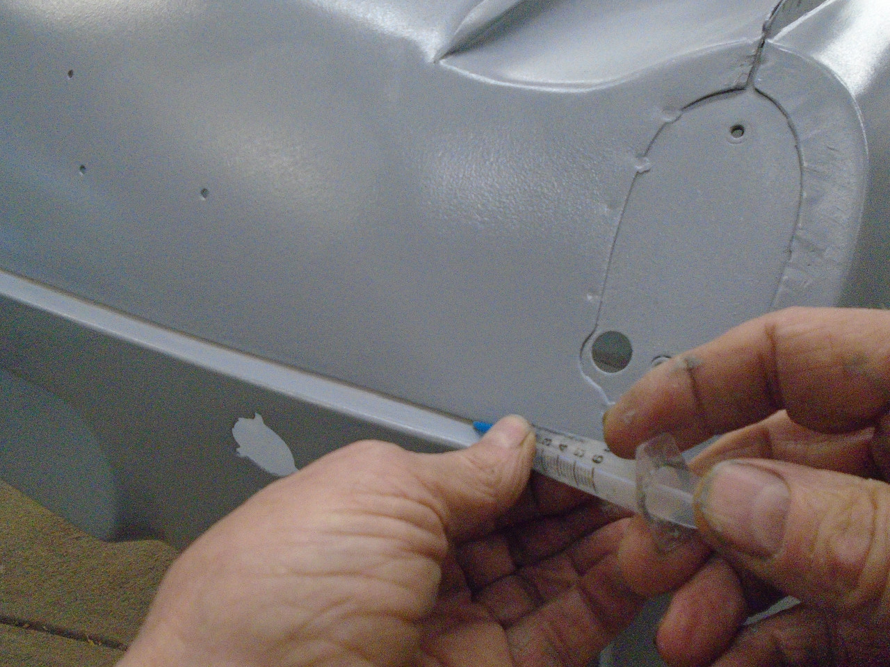
One sort sensitive seam is the horizontal one across the rear
valance. For this one I loaded some sealer into a syringe
with a small plastic tip so I could force sealer all the way to
the bottom of the seam. I could then tool it with a wet
finger without getting much on the surrounding surface.
I think the next step may be a little controversial in some
circles. When I did the TR6, I was a little queasy about
leaving the bottom surface of the tub with just body
color. Granted, it did have probably four coats of a good
epoxy primer under the color, but it still seemed like a that
little more protection for this very hostile environment would
have been good. I rationalized by reasoning that the
roadster, at least under my stewardship, would not likely see
much bad weather. I couldn't necessarily say that about a
GT car, though.
I decided to use a good quality undercoating on the bottom of
the tub. There are a few to choose from. Mainly from
the company reputation, and some good recommendations, I chose
3M Schutz. There is a paintable version of Schutz, but I
didn't really see the point of that. I've used the product
before on the TR6 rockers and wheel wells, so I knew that the
overspray can be difficult to remove. I spent some time
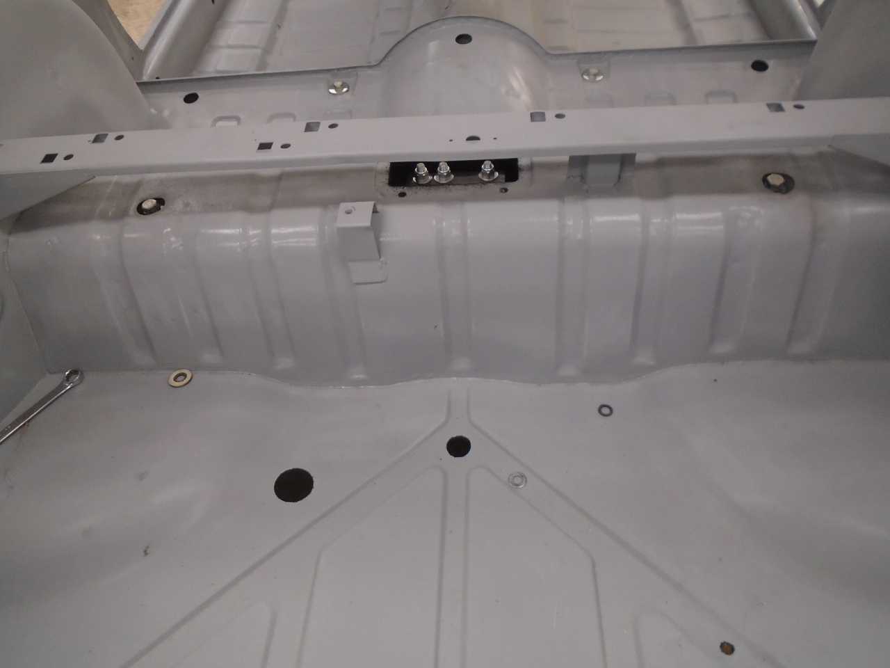
masking and taping over holes.

Then sprayed about two quarts on the underside and in the wheel
wells.
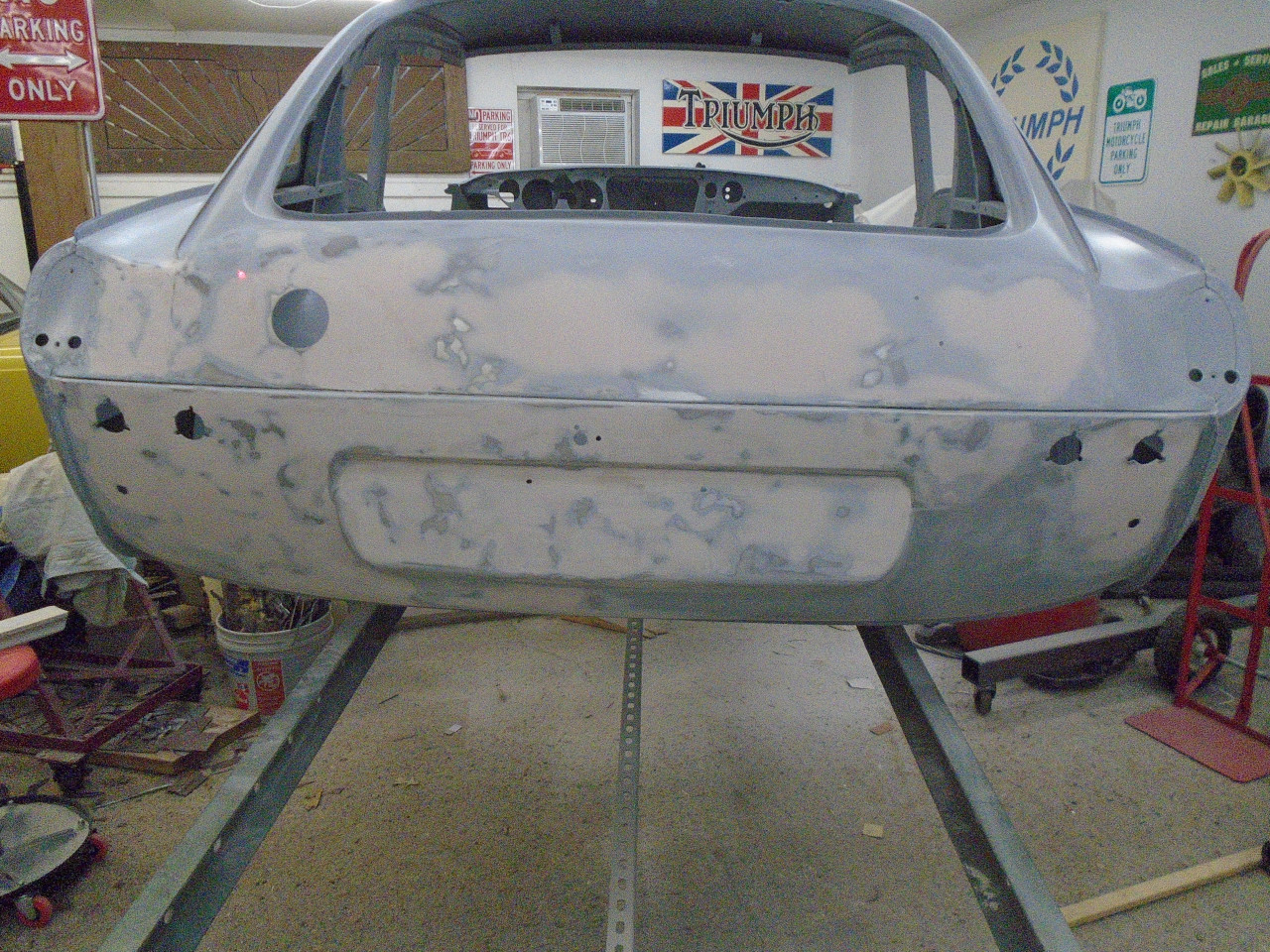
I also decided to do a little body work to the rear valance
before taking the body off the rotisserie. It was at a
much more convenient height for this work than on the
frame. At least two minor rear-end boo-boos and repairs
left some ripples in the metal back there. While I was at
it, I prettied up the more visible parts of the firewall and
environs.
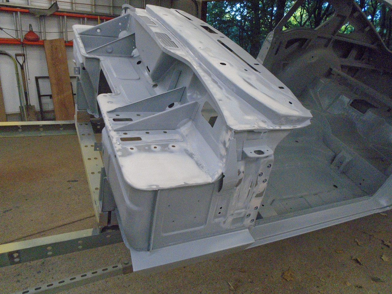
After this, the entire body got another coat of epoxy to cover
the filler and seam sealer.
OK, so much for prep of the body. Now for prep of the
chassis. First, I had to retrieve it from the top bunk
where it spent the last year.
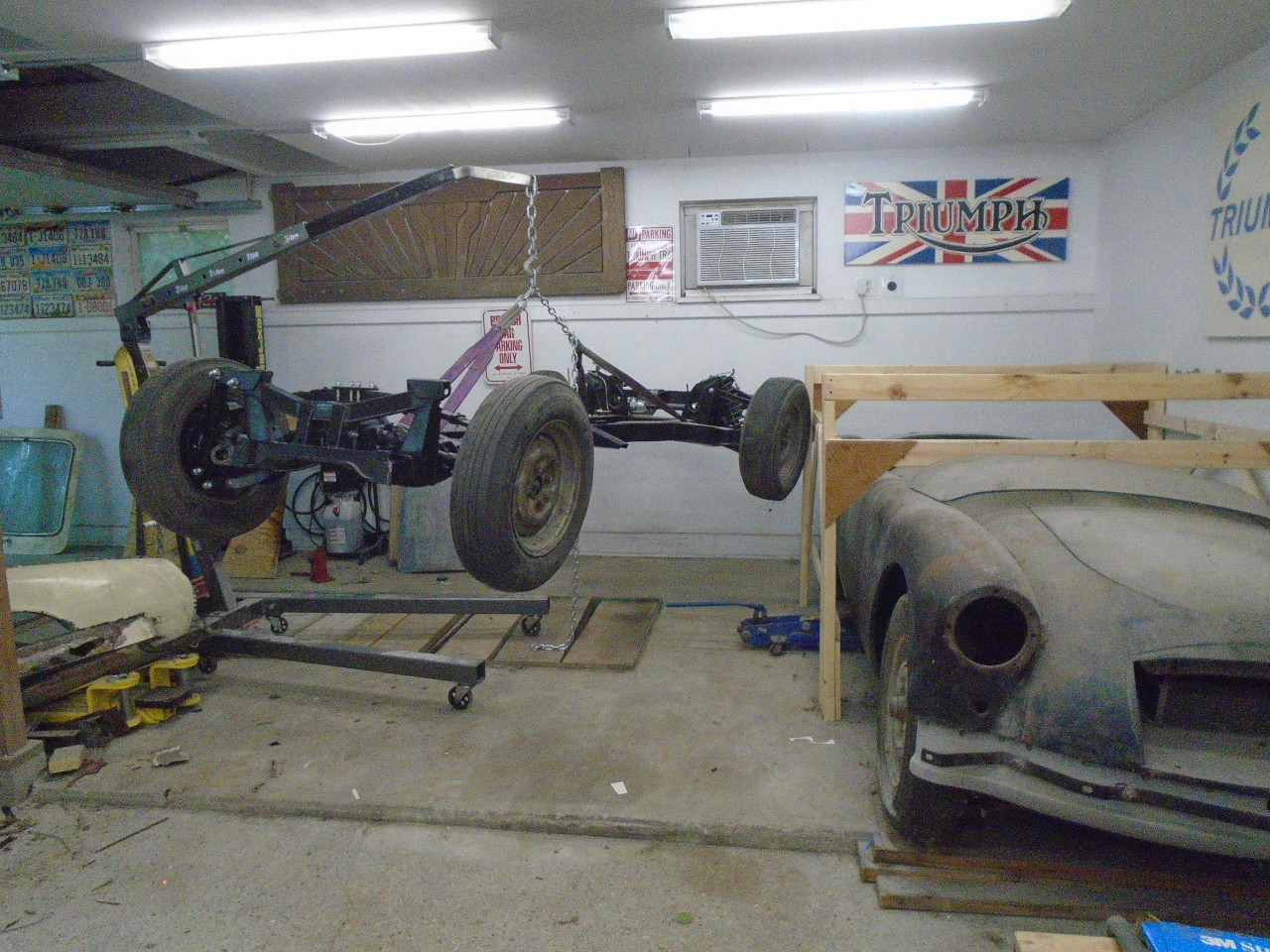
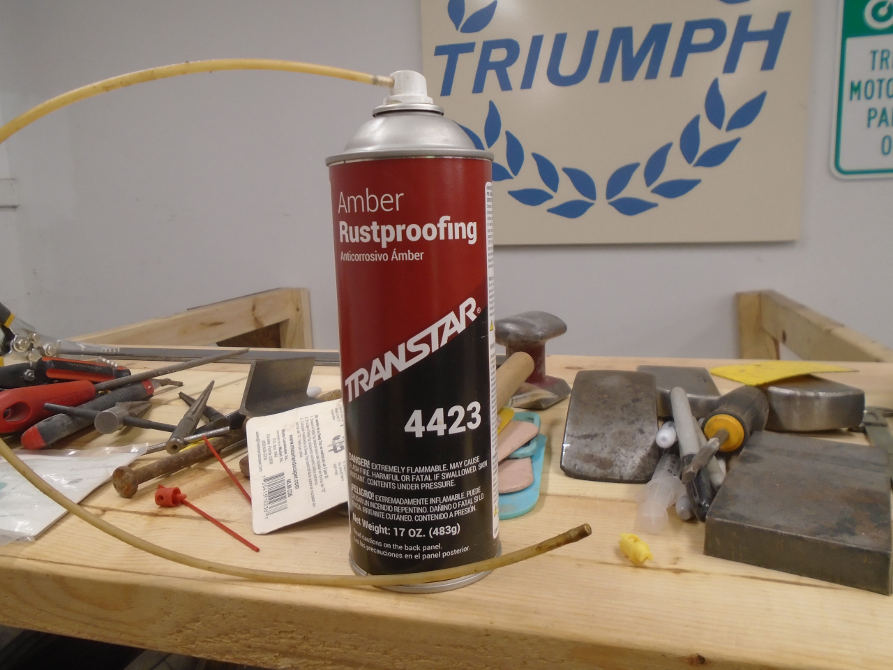
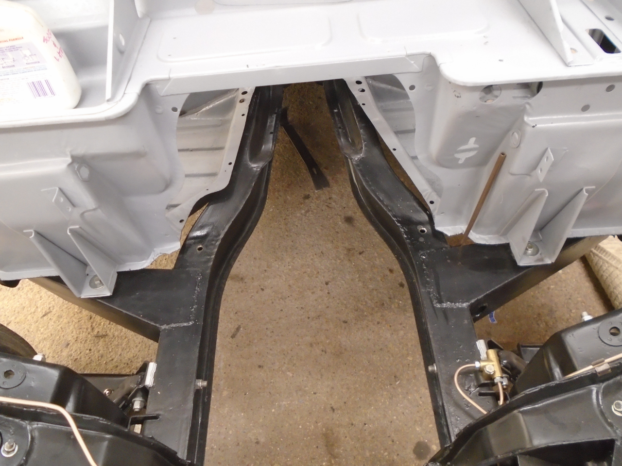
The first thing I wanted to do was do some rustproofing inside
the frame rails. I'm aware of, and have even used a
popular product called "Internal Frame Coating". As far as
I can tell, it is pretty much an ordinary zinc based paint, just
labeled and marketed for this very specific purpose. I
can't see anything about it that makes it uniquely suitable for
the insides of frames, other than maybe the extension tube and
remote spray nozzle that it comes with. Further, as with
any paint, success is heavily dependent on surface preparation,
and any meaningful surface prep inside a frame is just about
impossible.
My preference these days for rust protection of internal spaces
tends more toward the waxy substances that flow and penetrate,
but never harden. There are a number of products, most of
them appear to be similar. On this project, I used a
Transtar product. As a side note, it looks, smells, and
feels exactly like what Ziebart uses for interior
cavities. I assume it's the same stuff. I used the
remote nozzle that came with the Internal Frame Coating. I
was able to reach most areas of the frame through existing
holes, but I did have to drill a couple of new holes.
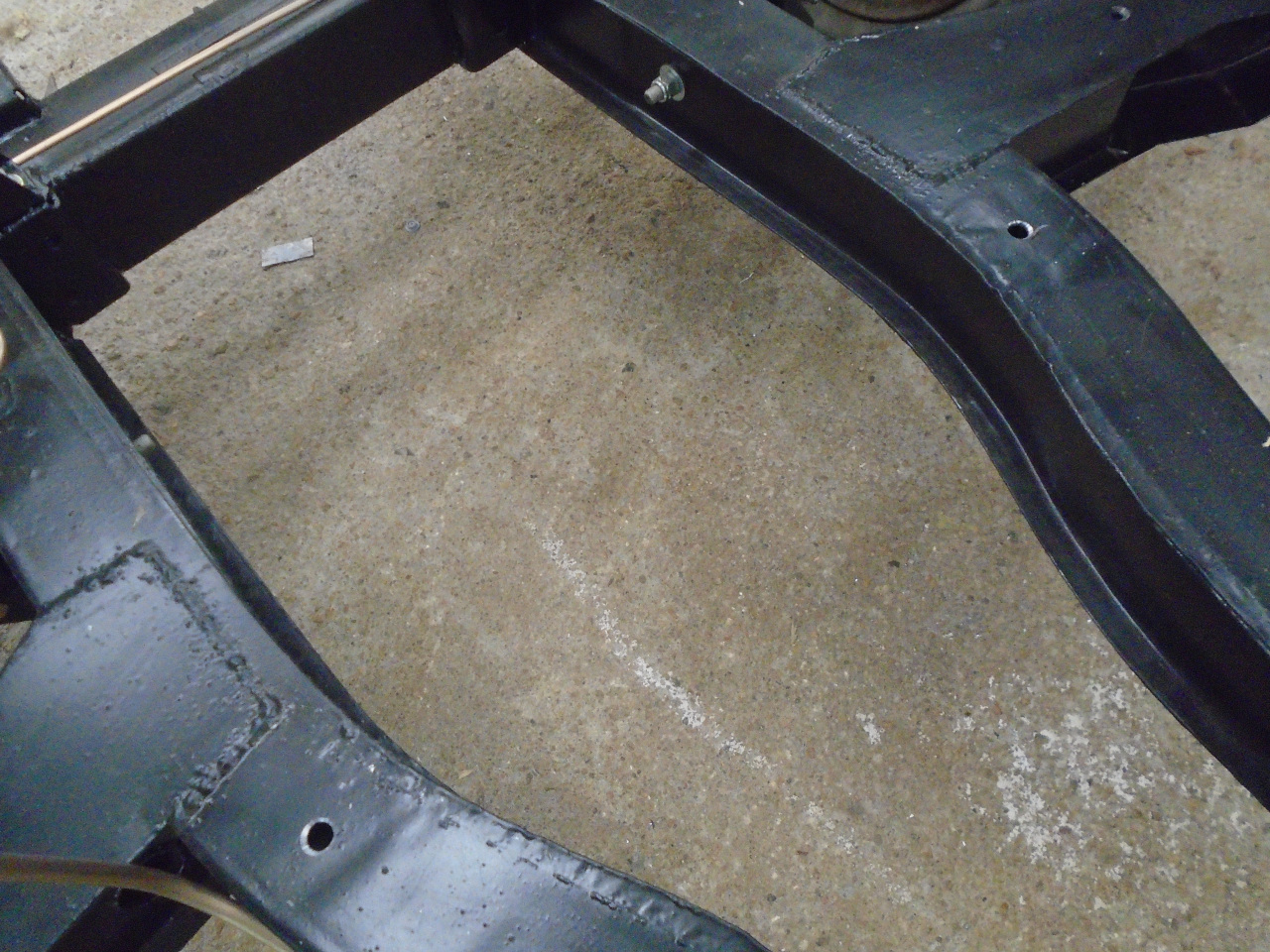
Then we come to the question of mounting pads that go between
the body and the frame--how many should there be, and where they
go. I checked all of the usual sources on this topic, and
found that there is no clear answer. The factory Workshop
Manual doesn't show any mounting pads. Some of the vendors
show them, but they don't agree as to number, type, and
location. The only thing that the Workshop manual says it
to put a ring of sealant around each mounting point on the
frame. So I did that.
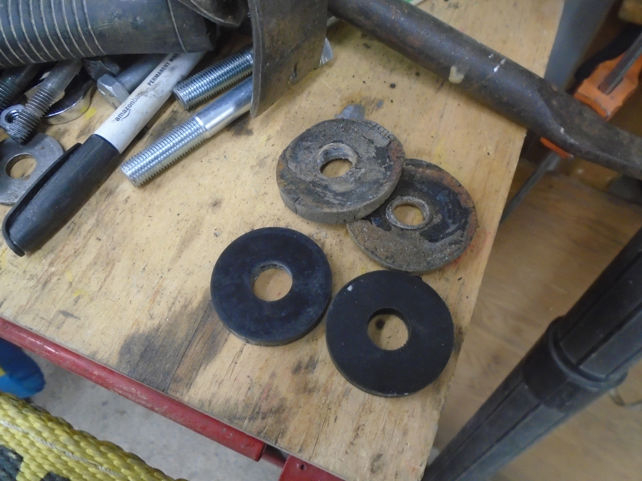
One other clue I had was the pads I removed from the car at
disassembly. There were two 1/4" thick aluminum pads and
two similarly sized rubber pads. The semi-helpful note I
had included in the Ziplock bag said "Alum at front".
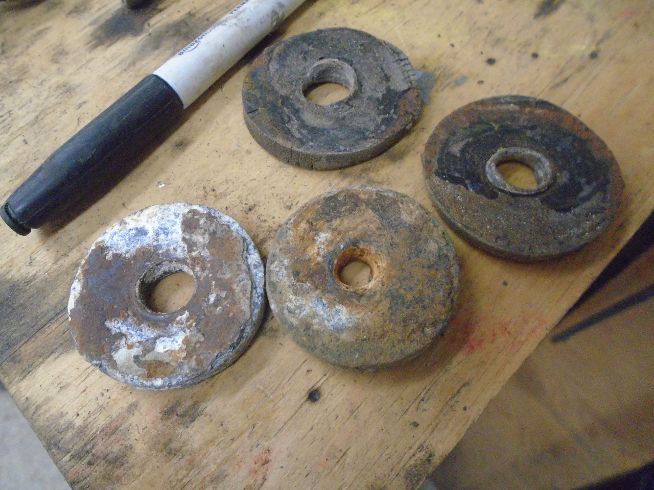
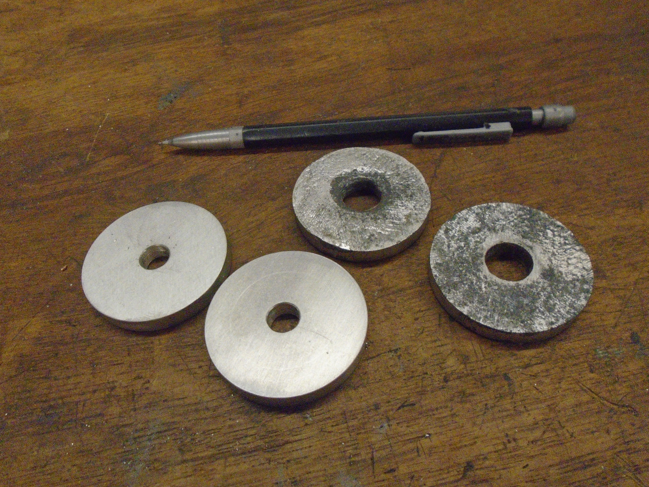
I had ordered half a dozen rubber pads, but just made a pair of
new aluminum ones to replace the severely corroded originals.
With all of the uncertainty about mounting pads, I decided to
just drop the body on the frame and see where the spaces were.
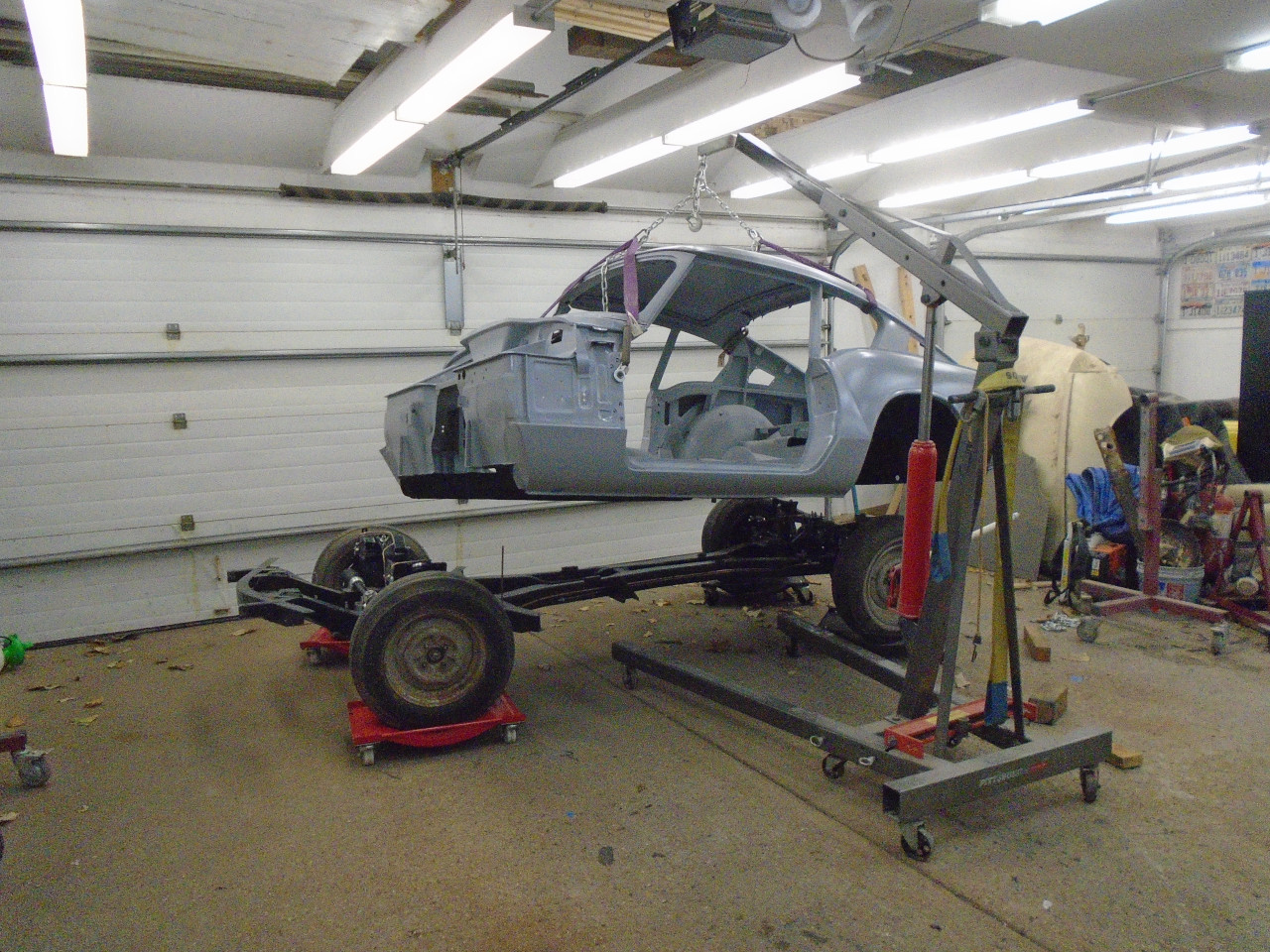
This resulted in the body rocking on one of the center pairs of
mounting points, clearly showing that pads were necessary at the
front or rear or both. I recalled the Ziplock clue, and
put the new hard spacers at the front, and a pair of rubber ones
at the rear. This seemed to stabilize the body
nicely. On inspection, I found that the rear outriggers
had about a 1/4" space between frame and body, so I stuffed a
pair of rubber mounts on each side. This is where I left
it.
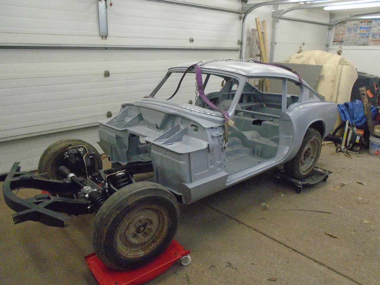
I rounded up all of the original body mounting bolts, stripped
them, plated them, and re-used them. Washers got replaced.
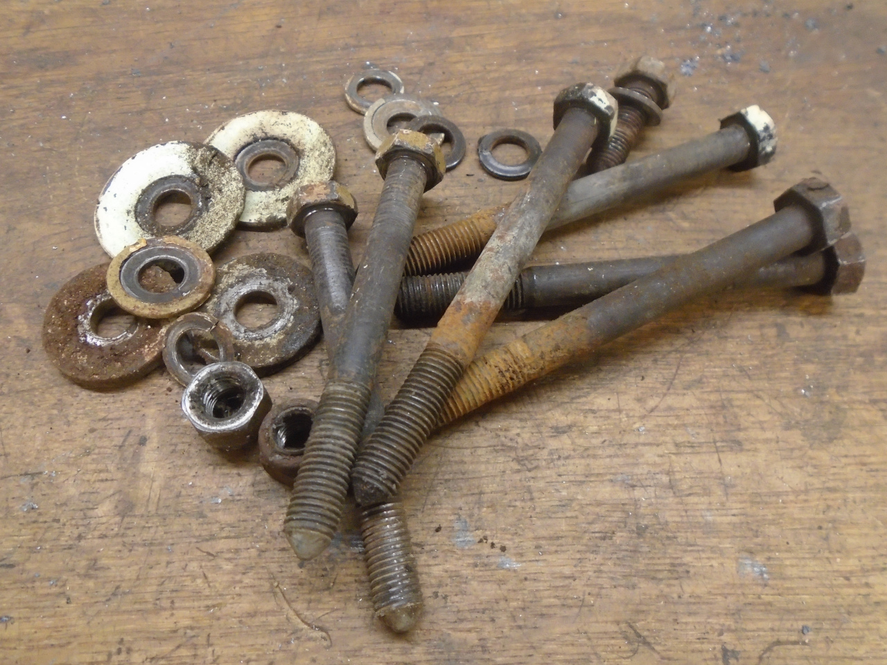
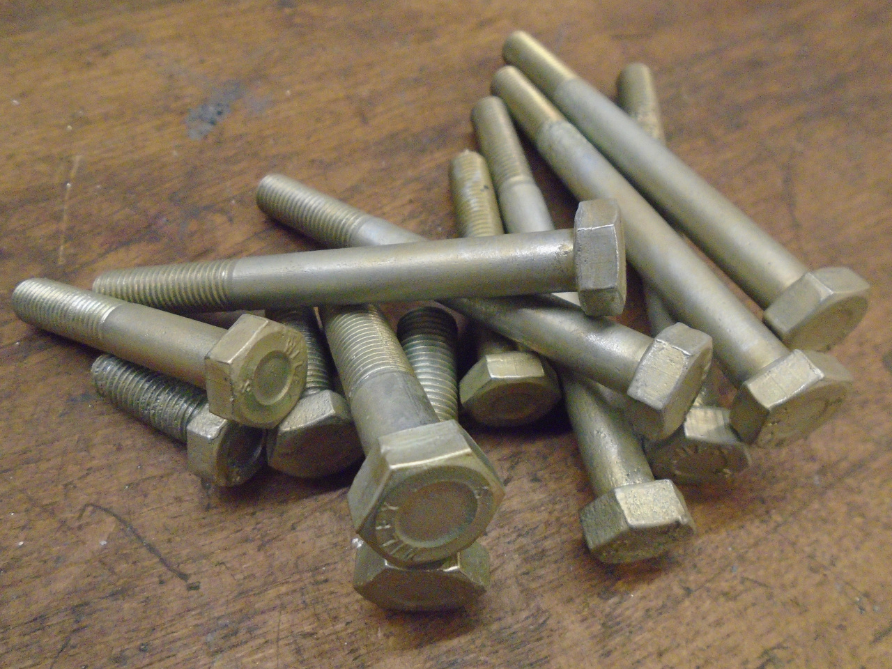
Some minor shifting got all the 12 mounting holes lined up well
enough to fasten her down.
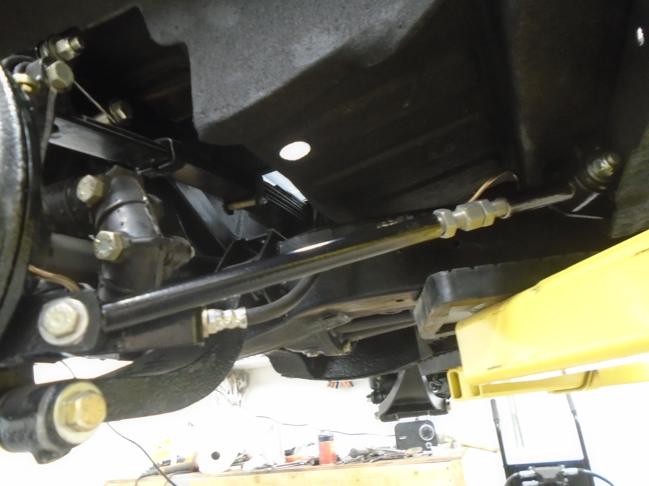
Having the body finally back on the frame then allowed a couple
of other areas to be finalized. One is the hard brake line
that runs across the car from one side to the other at the
rear. It is fastened to the body by a couple of clips that
are often forgotten when the body is lifted off. This
usually mangles the line pretty badly. I straightened it
out well enough to use as a pattern for a new copper-nickel
line. I couldn't really get a good pic of the line in
place.

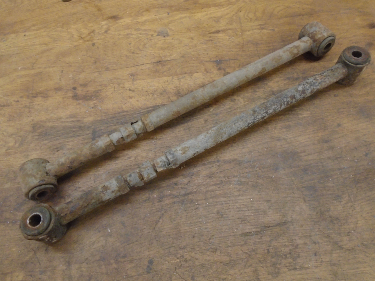
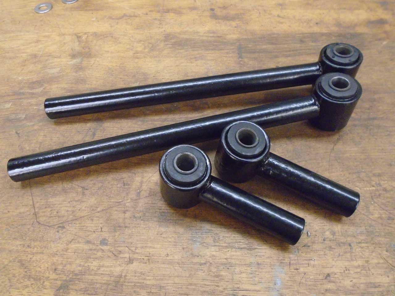
The last thing to do was to tend to the radius arms, which
attach to the rear suspension and the body. These
adjustable links stabilize the rear suspension, locate it in the
fore/aft position, and allow for adjusting the toe in at the
rear.
My links were pretty corroded, but did come apart after some
coaxing and threats.
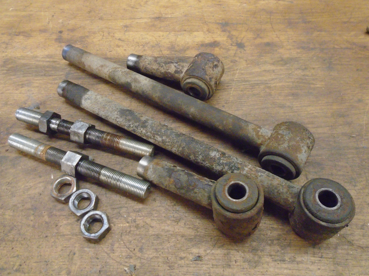
All was well, except one of the adjuster lock nuts decided to
gall and strip the threads.
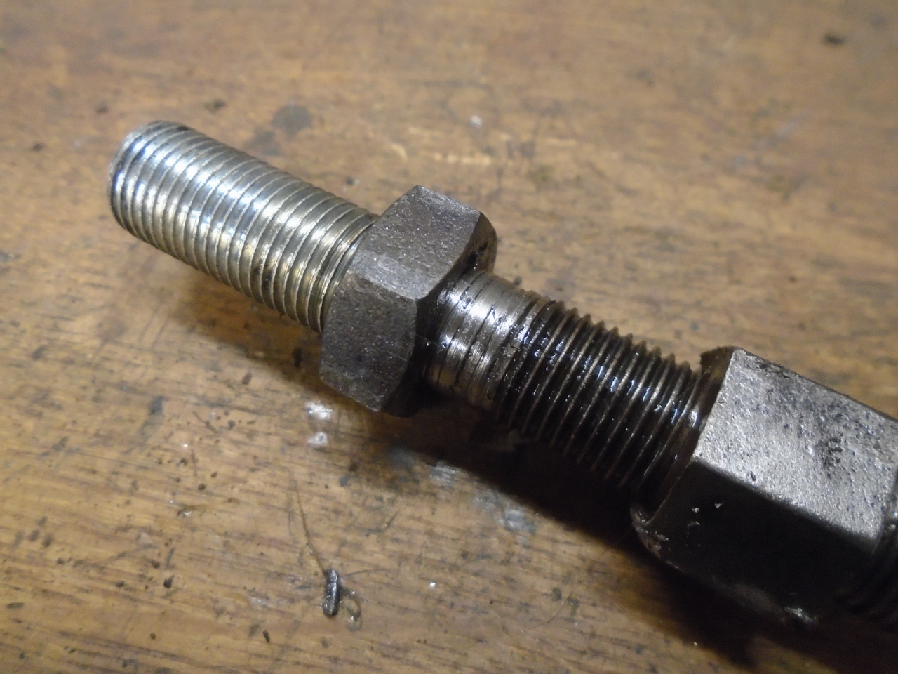
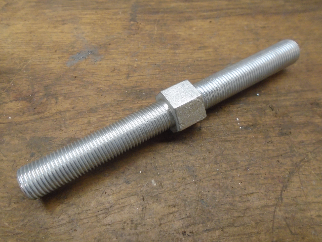
These links are essentially just turnbuckles, with left and
right hand threads on the adjuster, and while I thought about
just making a new adjuster, I found that just buying one was
cheaper than the 1/2-20 Left Hand die I'd have to get. So
I ordered one.
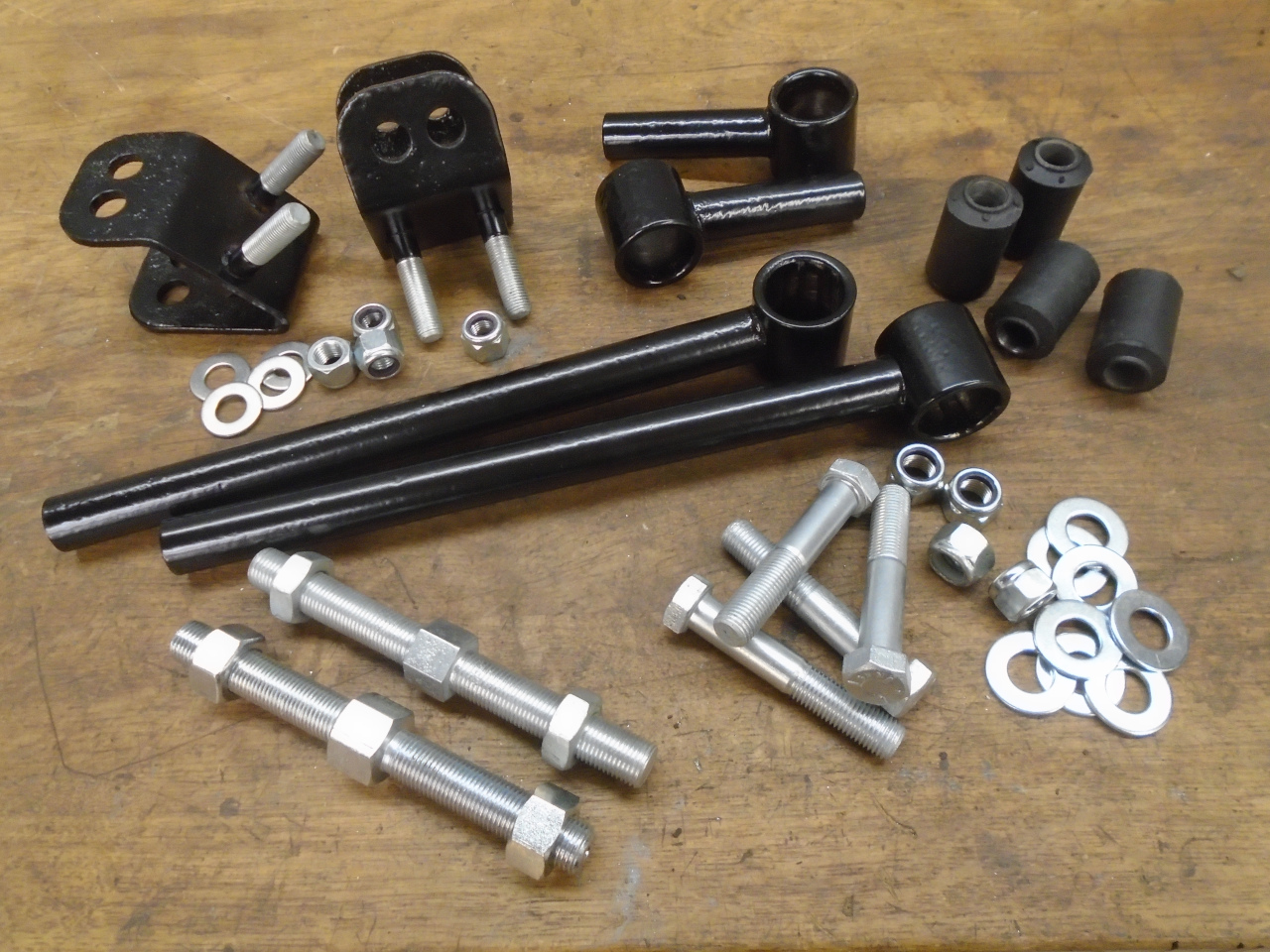
While waiting for the adjuster, I removed the rubber bushes from
the link arms and cleaned them up.
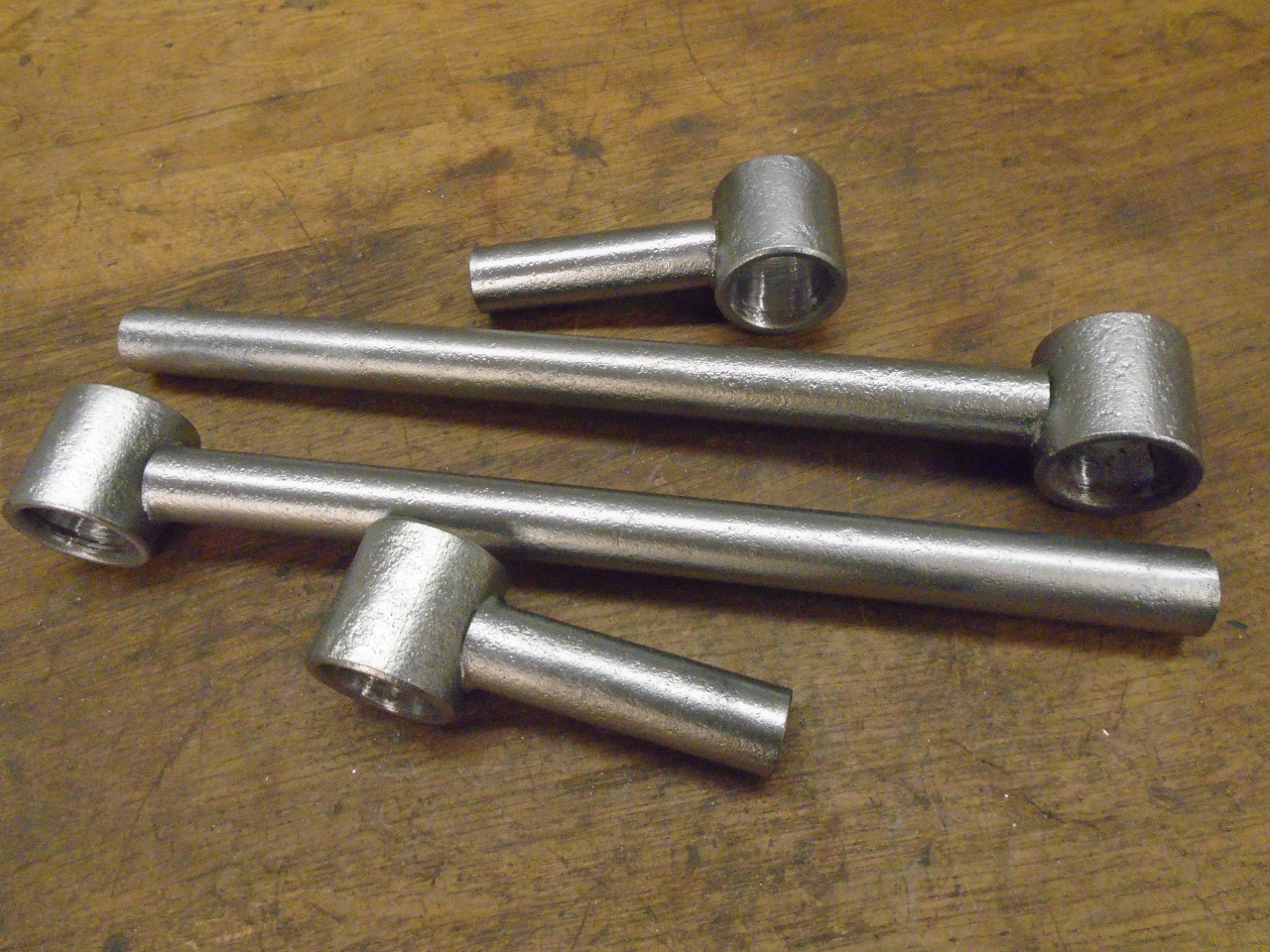
Then turned to the brackets that mount to the body.
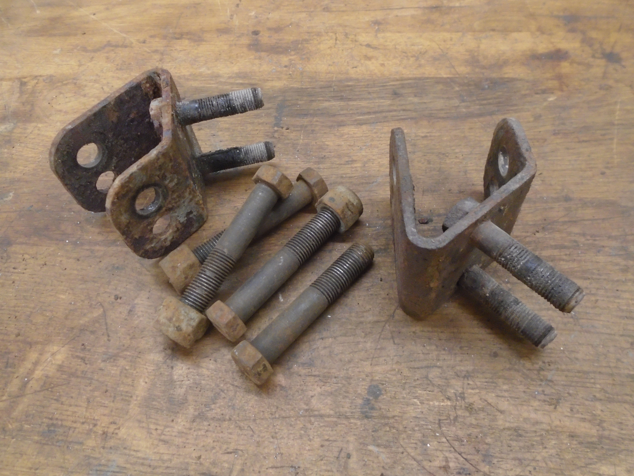
These are a little problematic in terms of rust
protection. It would be hard to get plating to reach to
the inside of the sharp bend of the bracket, while powder
coating can't really be used on threads. In the end, I
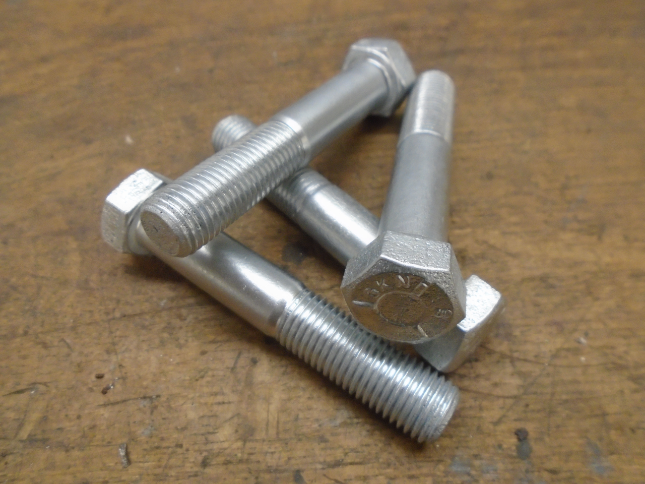
just selectively plated the studs, and powder coated the rest.
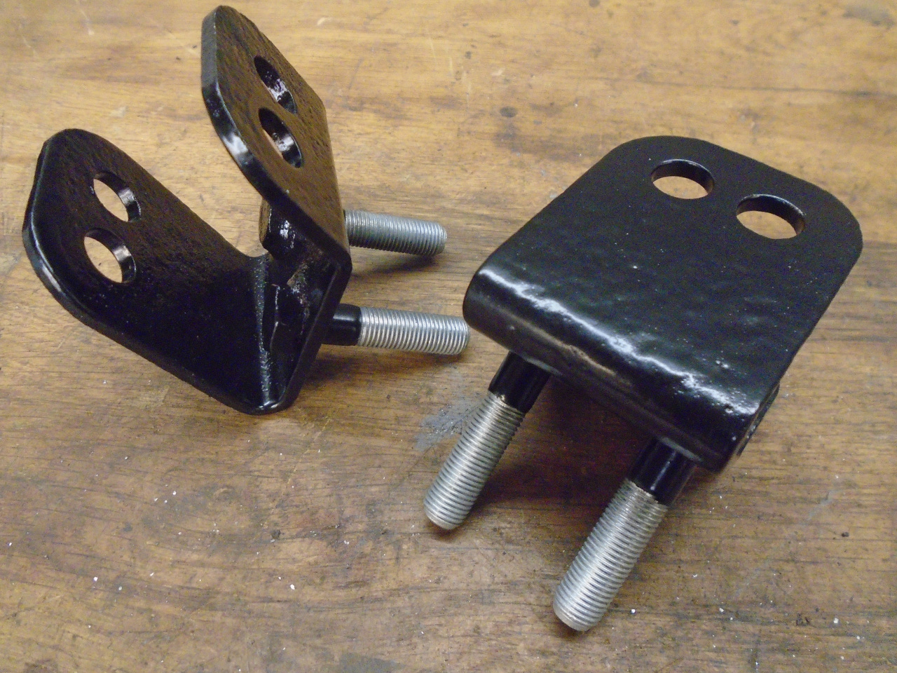
The surviving adjuster and the mounting bolts plated
nicely. Plating original hardware does take some time, but
it always fits, saves a little money, and the distinctive head
markings are something that some future restorer might care
about.
Finally, with all the parts in, I could assemble the arms...
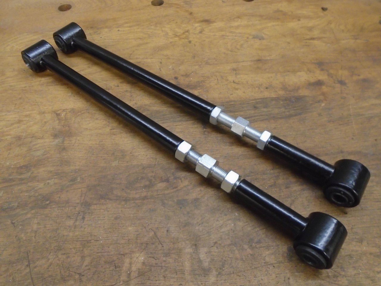
...and put them in place. I measured the arms before I
took them apart so I could return them to the original
measurement before final alignment.
This feels like another milestone. One important thing is
that by reuniting the frame and body, I've drastically reduced
the storage space needed for the project. Not much cost
here, either. Just some consumables, and bushes and the
adjuster for the radius arms.
Comments to Ed at elhollin1@yahoo.com
To my other GT6
pages.