To my other GT6
pages
September 19, 2020
Rear Damper Brackets
The earliest GT6 cars apparently had a simple swing
axle arrangement at the rear with a very typical tube damper
spanning from a stud on the vertical link to a bracket on the
frame. With the advent of the MK2 in 1969, the rear drive
design was upgraded to include a rubber "Rotoflex" joint at the
outboard end of each half-axle. While this did improve
performance, it also required that the top damper attachment be
relocated. The damper had to be swung outward to avoid
fouling the Rotoflex, and Triumph Engineers chose to create a new
top damper fixing point on the inside of the wheel well
itself. Many people feel that attaching a damper (and bump
stop, by the way) essentially to body sheet metal was a bad
design.
The top damper bracket was welded to a doubler plate that was in
turn welded to the wheel well sheet metal.
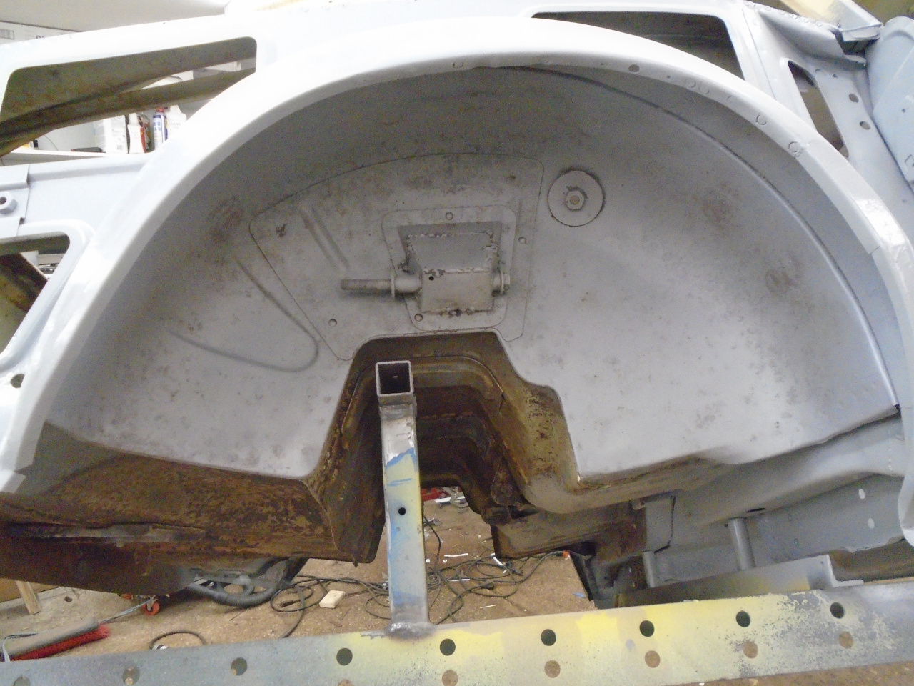
While that view may not look so bad, the fact is that water found
its way between the doubler and the wheel well, and went to work.
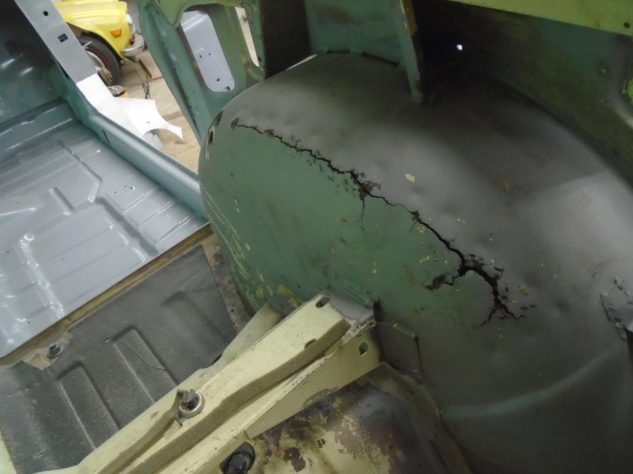
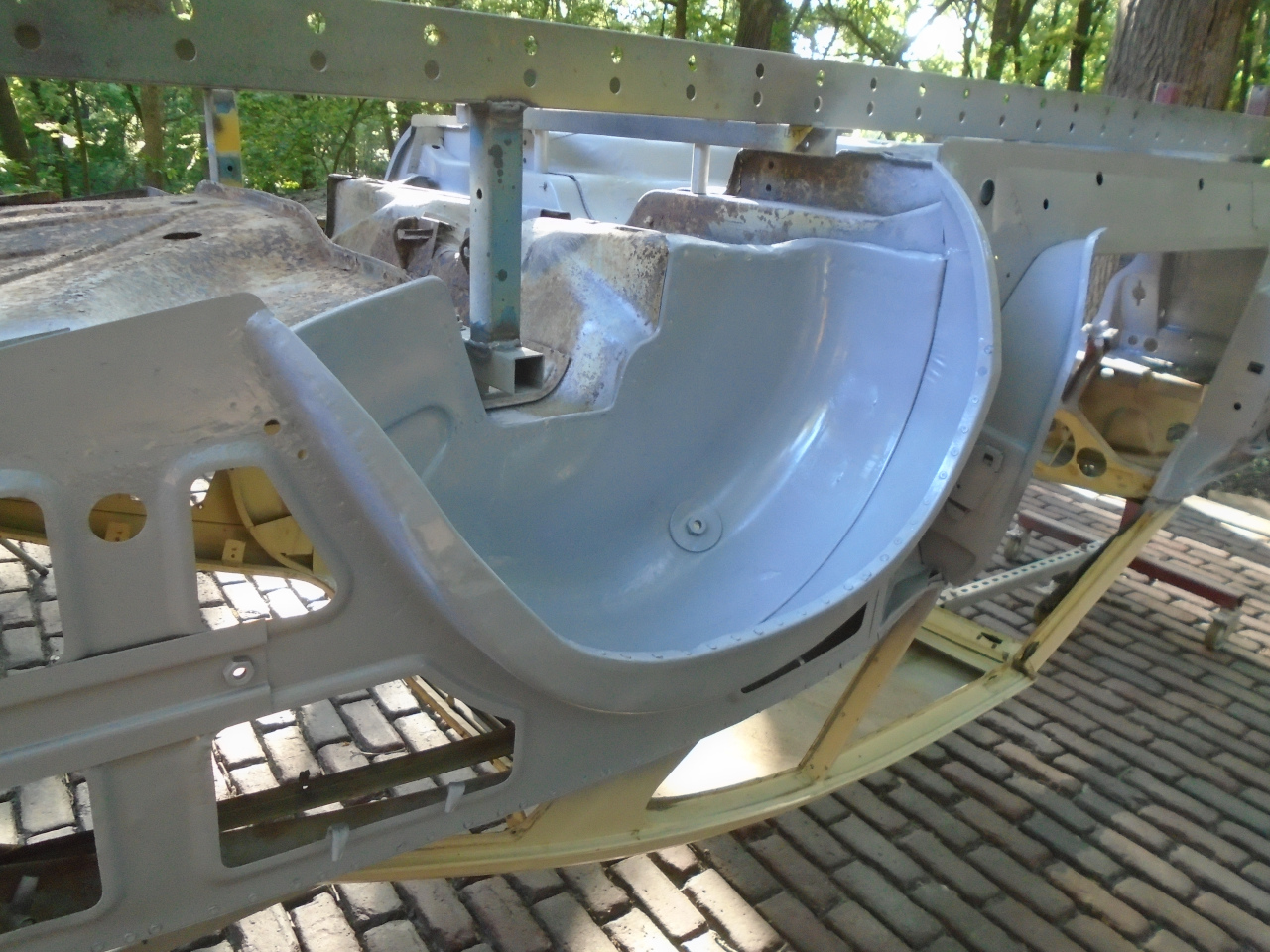
I managed to repair
the wheel well on both sides, but couldn't bring myself to
recreate that factory damper bracket.
I'm not the first one to feel this way, and there is even a
commercial solution available to move the top shock fixing back to
the frame, using an extension from the old MK1 mount point.
Though it's easy to order the kit to make the change, my Inner
Engineer rose up and parked himself between me and my keyboard.
"You don't need to order that", he said, "It's a good solid
Engineering problem to solve! Piece of Cake!"
"I don't know", I protested. "Seems like a lot of work."
"You really need to do more to keep your skills up, Dude", he
said, rolling his eyes. "Now close that window and open up some
CAD!"
So I did. I took some measurements from the suspension and
mocked up a simplified version of the mechanism.

The fixed line at the right represents the frame itself. The
upper horizontalish line is half of the transverse leaf
spring. The leftmost line is parallel to the plane of the
wheel, while the verticalish line just to it's right represents
the vertical link. The two diagonals that end in mid air
represent the tube shocks, the right one being attached to the
original MK1 chassis fixing point. The other one is the new
shock orientation, and the new adapter bracket's job is to span
between those two upper red dots.
The three red dots at the left represent, from bottom to top, the
point at which the axle hits the frame, the intended lower limit
of suspension travel, and the upper limit of suspension
travel. Since there are no explicit bump stops in this
design, the damper itself determines the distance between the two
limits.
The commercial design uses the original MK1 shocks, so I did,
too. In effect, the adapter just rotates the original MK1
shock outward just enough to clear the rotating axle parts.
Making the shock more vertical has other effects, though.
The travel of the MK1 shock itself is about 2 1/4 inches, but for
an angled shock, this translates to a little more travel at the
wheel. A more vertical shock reduces the travel.
So, I fiddled with the shock position and orientation for a while,
trying to balance the requirements: stay clear of rotating axle
parts, keep the axle from hitting the frame on rebound, and try to
keep suspension travel as close to stock as possible.
In my final design, the model predicts about 2 3/4" of travel at
the wheel. This is less than the MK1 travel, which I believe was
over three inches. It predicts about a minimum 1/4" gap
between axle and frame on rebound.
Now, I couldn't really take the predictions of this model as
gospel, mainly because it was so hard to get precise 2D
measurements from the actual 3D suspension. So the next step
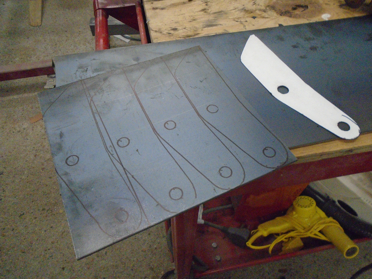
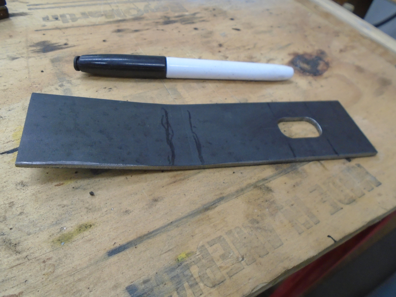
was to actually build the adapter. From computer model
measurements, I made a paper template to fit the existing bracket.
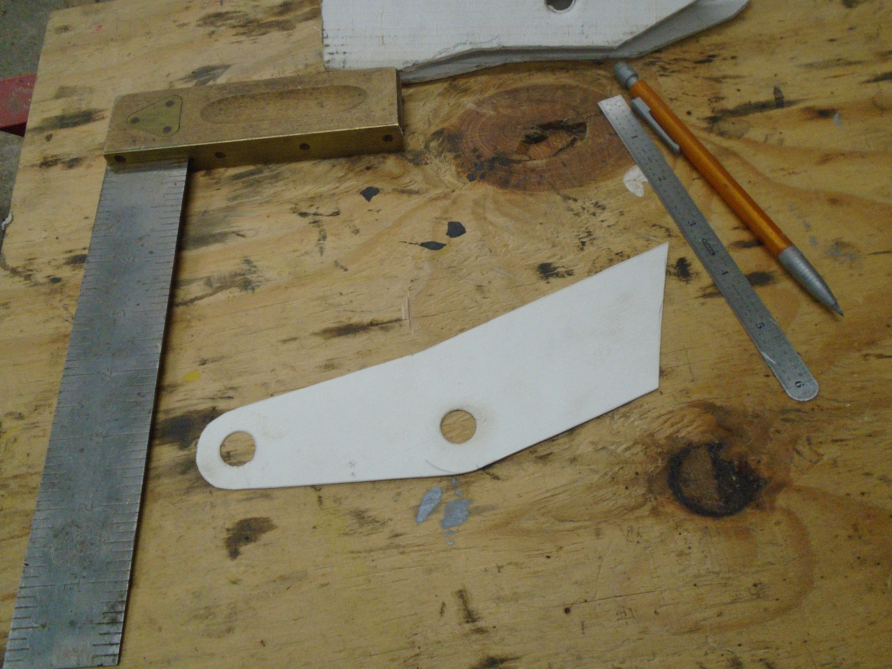
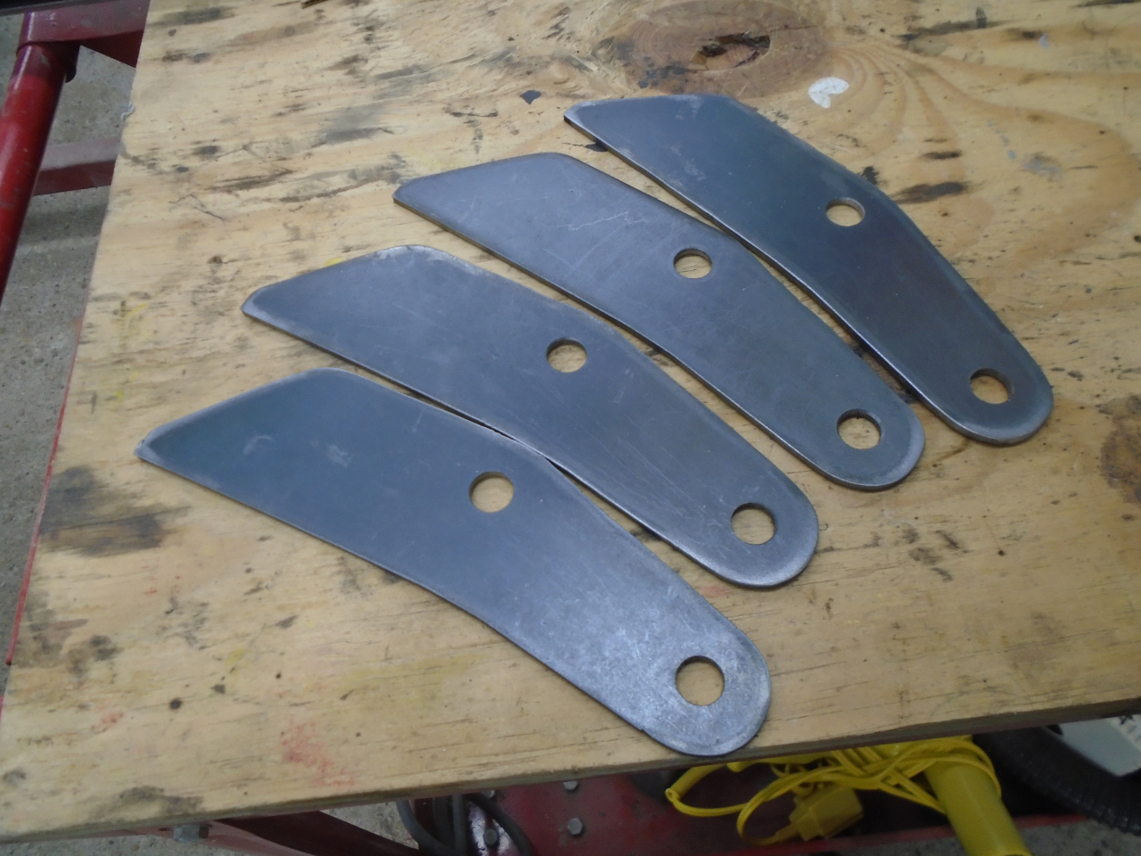
Then, cut some parts from 1/8" (11 gauge) steel. I was
feeling confident, so I cut parts for both sides.
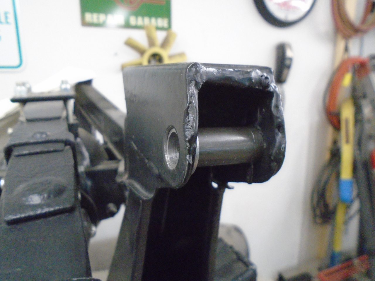
The adapter would attach to the original bracket using the
original shock mounting hole, but it seemed like a good idea to
install a spacer inside so cranking down on the fastener wouldn't
just distort the bracket. Unfortunately, the hole on the
forward side of the frame bracket was larger than the other
one. This was probably because a large shoulder bolt was
used to fix the shock.
So, to get a spacer to work, I made these little stepped washers
to adapt the hole.
At this point, I could take some measurements to see if I still
agreed with the model. So far, so good. Next up was a
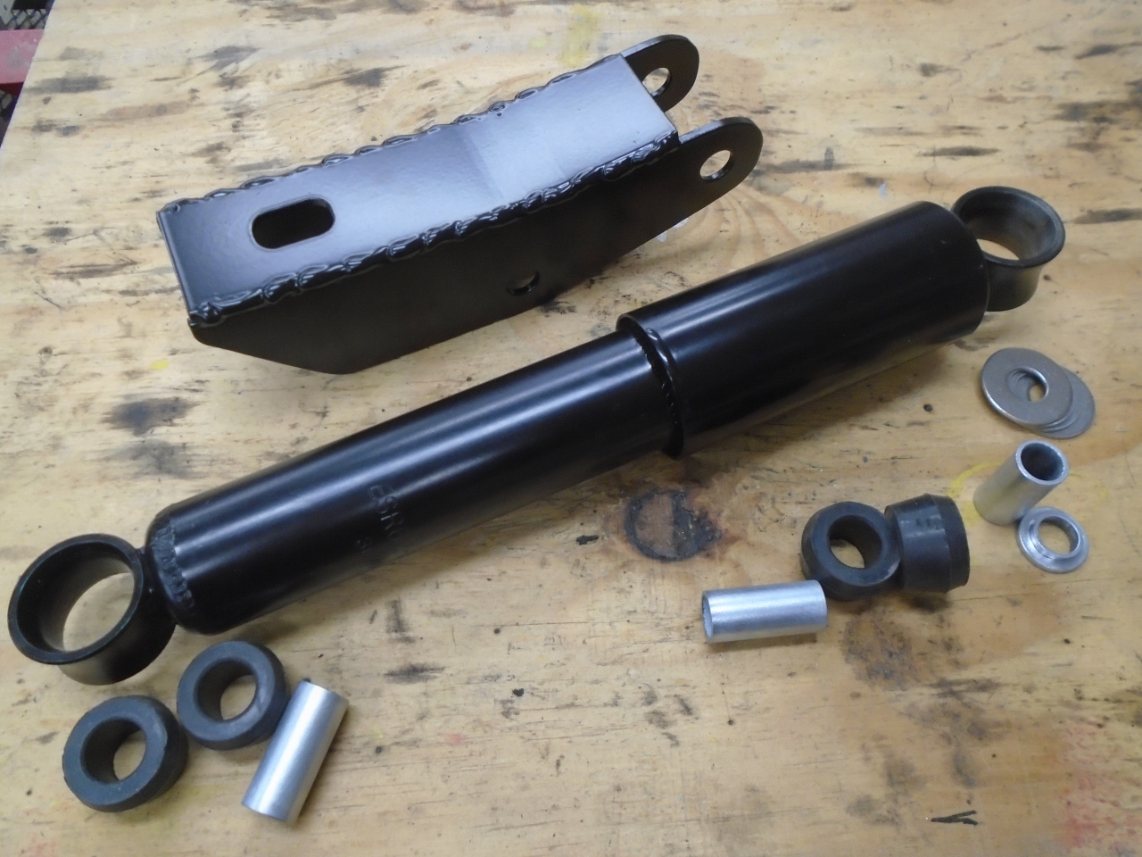
top piece to connect the two side pieces. This is
essentially the same design as the commercial adapter.
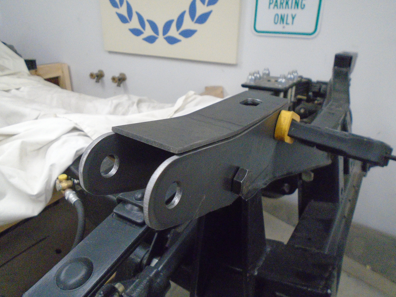
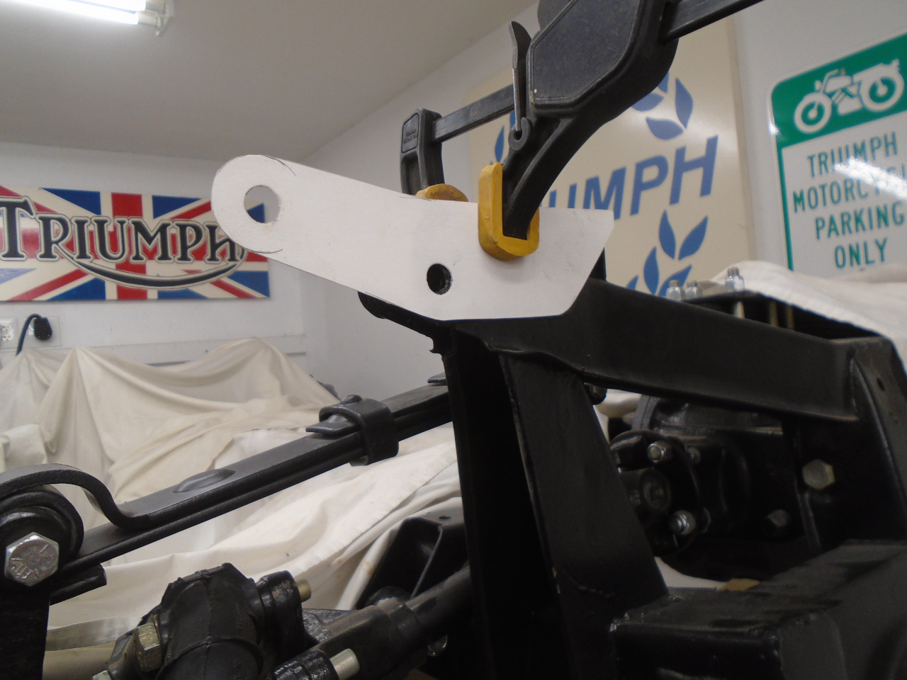
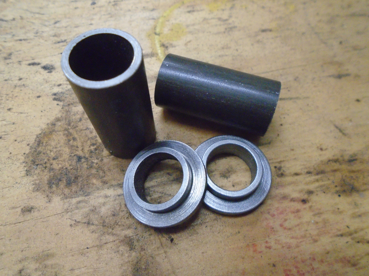
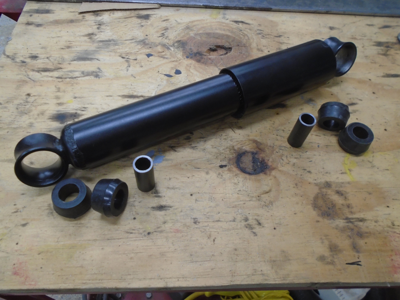
Before welding, I wanted to actually mount the shock. This
is a MK1 shock. It came with the rubber bushes, but not the
internal distance pieces. I had to make those.
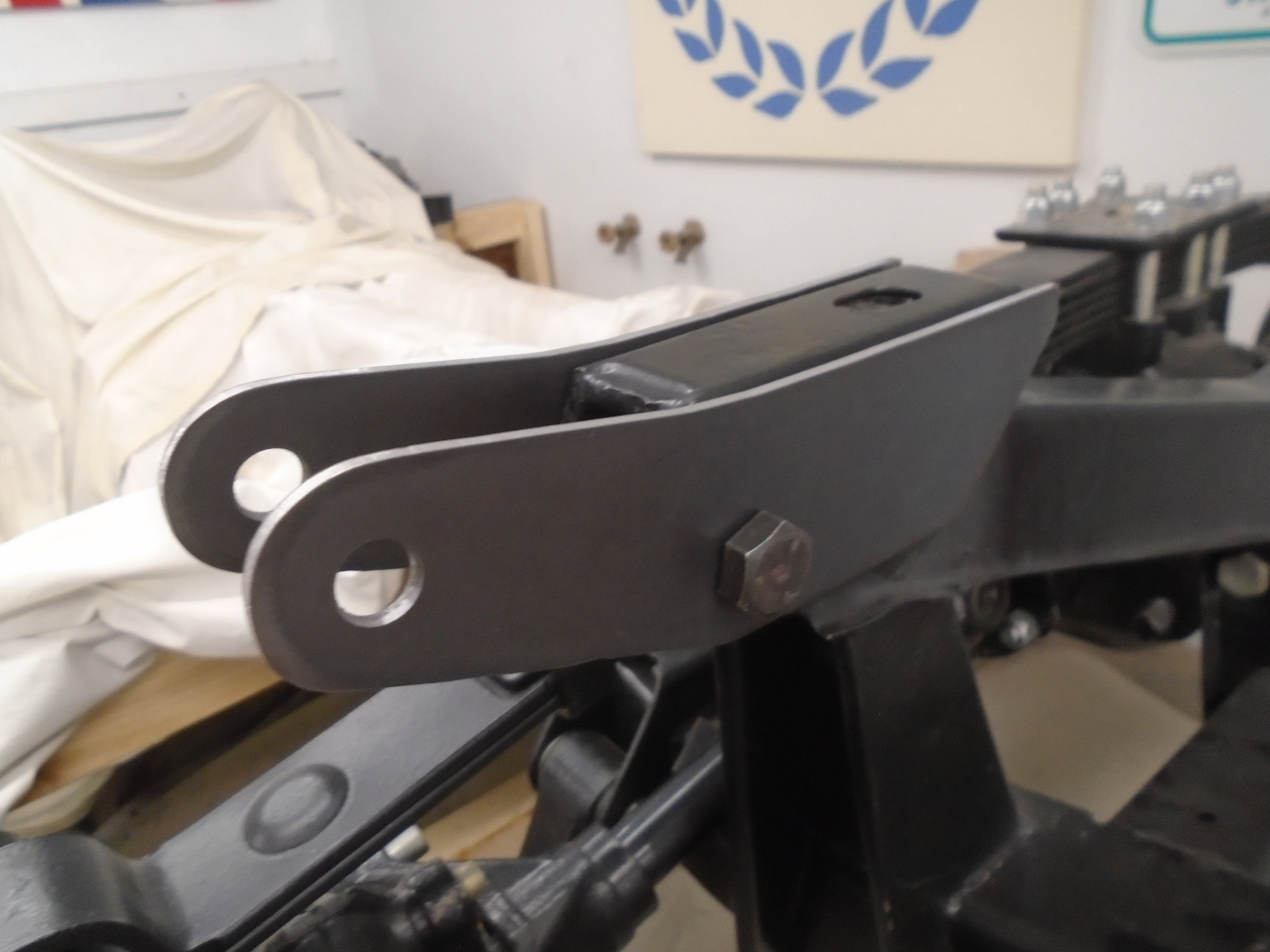
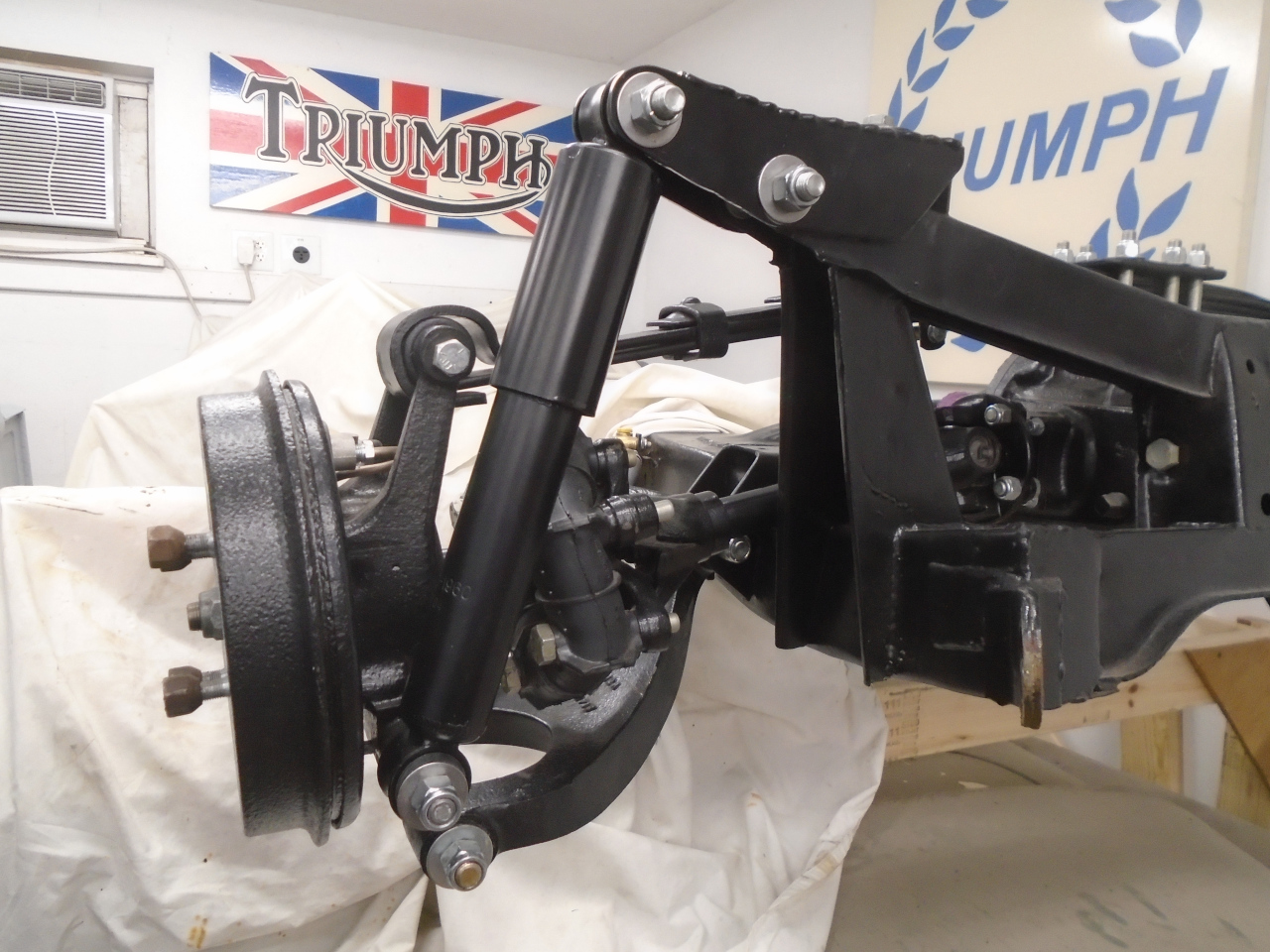
Installed the shock, and everything still looked good, so welded
'er up.
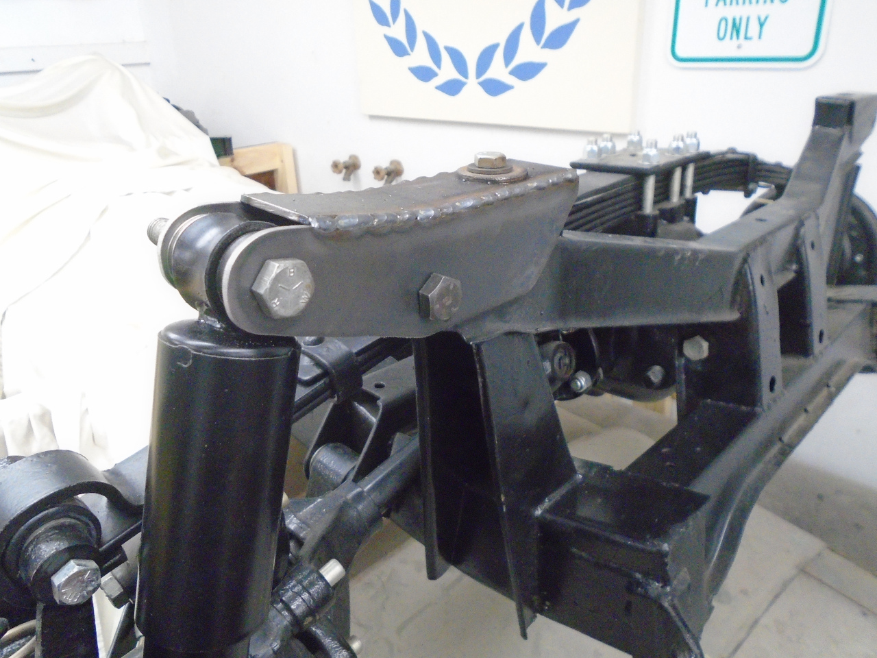
Took it all apart, powder coated the adapter and plated the
hardware.
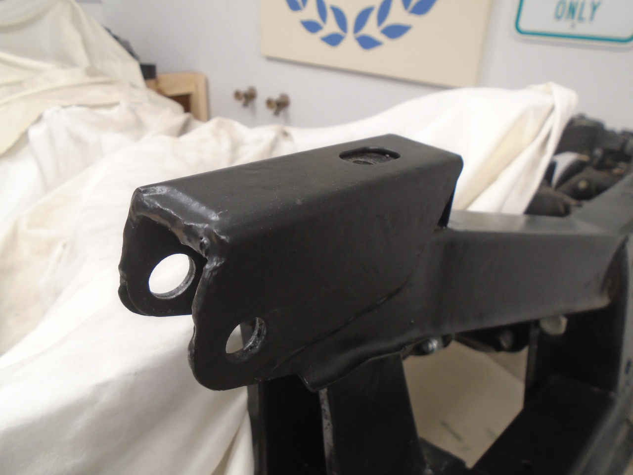
And put everything back together.
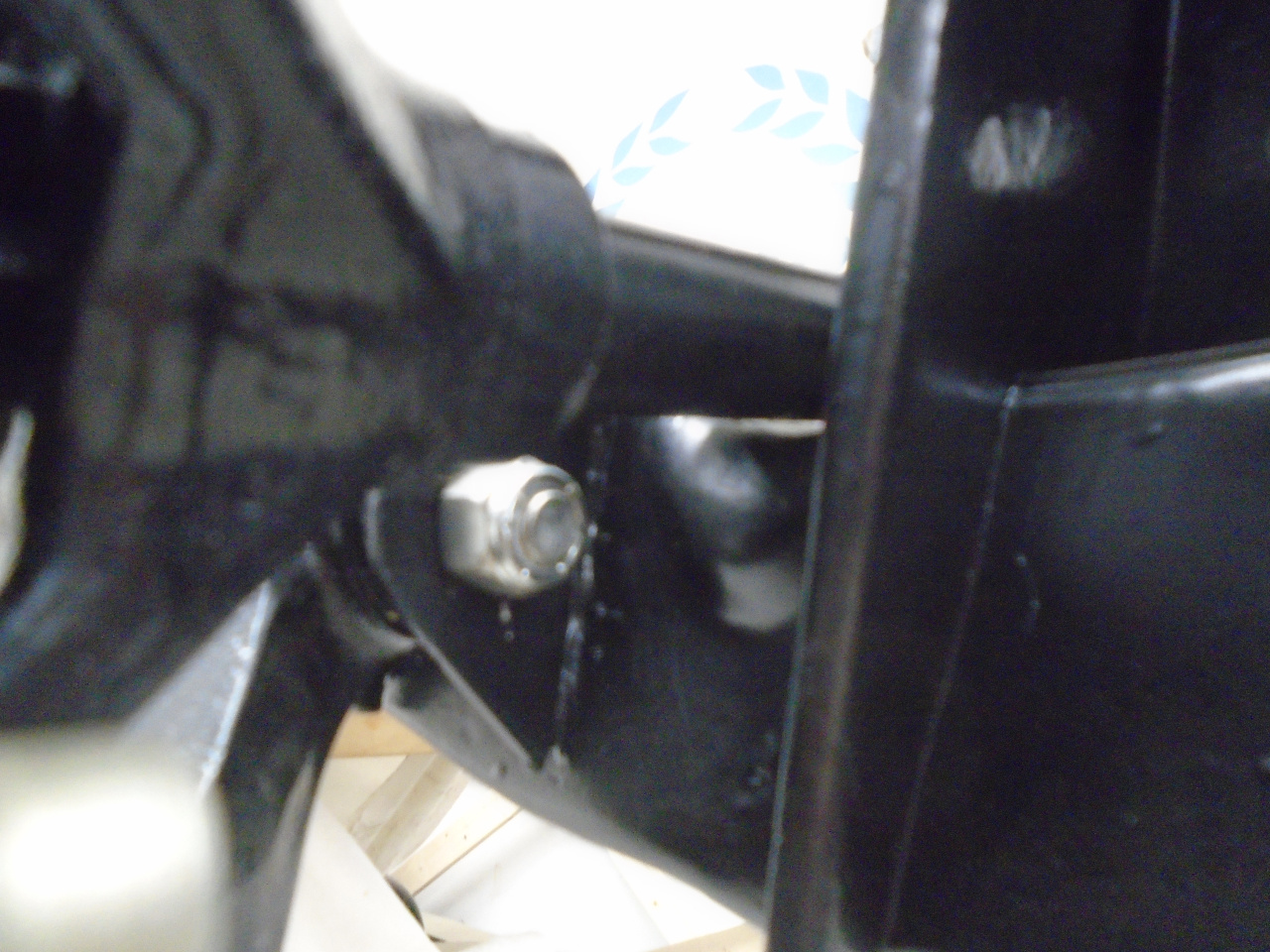
Hard to see in this bad pic, but with the suspension hanging from
the shock, the axle is about 1/8" from the frame rail. I
wish it were a little more.
I compared the dimensions of my final adapter with those that a
fellow enthusiast sent me that were reportedly taken from one of
the commercial adapters. They were very close. So, I
consider the design good enough. Right now, the chassis is
up on its top bunk and against the wall, so I can't do the other
side until I bring it down.
Even though my Inner Engineer sort of bullied me into this
exercise, I really do enjoy this kind of hands-on
engineering. I'm not sure what the commercial adapters cost,
but these were less than $10, just for steel and hardware.
Comments to Ed at elhollin1@yahoo.com
To my other GT6
pages