To my other GT6
pages
March 3, 2020
Speedometer and Tachometer
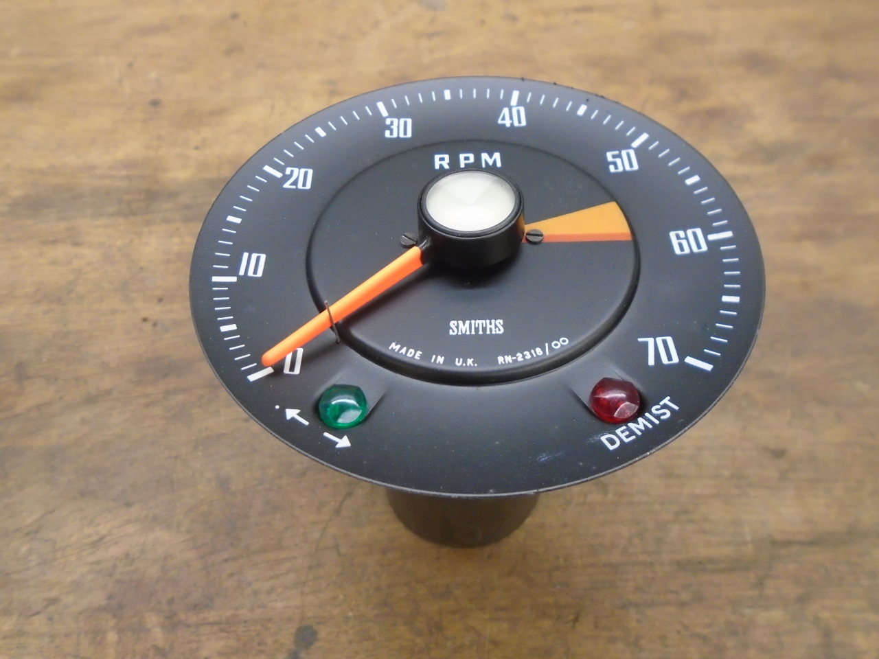
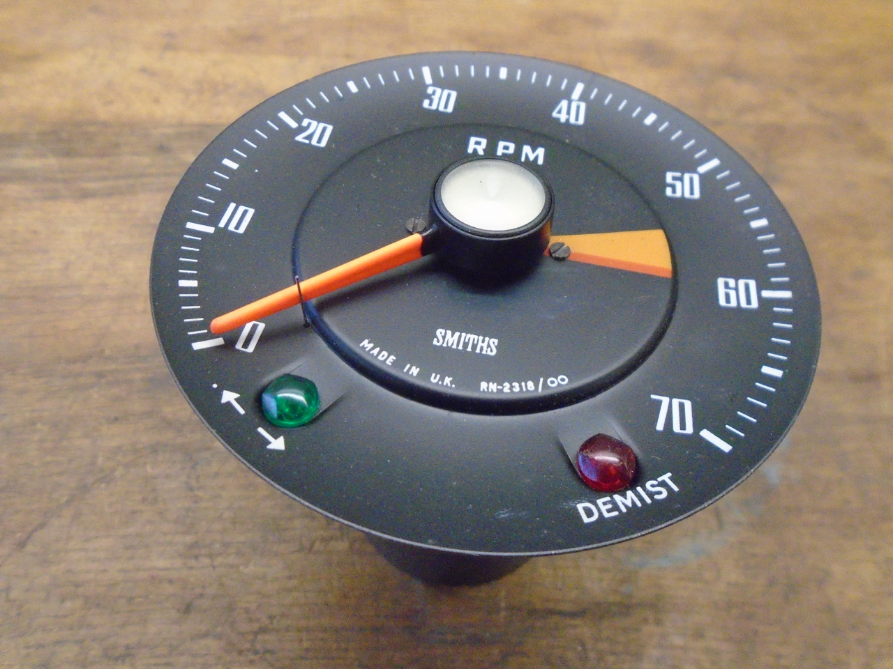
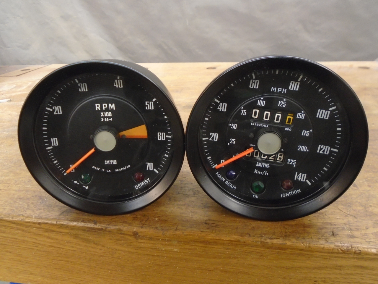
GT6 cars of course came with a speedometer, but
also with a matching tachometer as an obligatory piece of sports
car hardware. They are simple mechanical instruments, not
really designed or built for either longevity or repairability.
These rudimentary instruments both work on the same principle,
and have a lot in common internally. A cable with a
spinning inner core is connected to the back of the instrument,
and turns a spindle attached to a bar magnet. The magnet
is housed inside, but not touching, an aluminum cup. The
spinning magnetic field induces currents in the cup, which in
turn generate their own magnetic field. The two fields
interact such that the aluminum cup wants to spin with the
magnet. But the cup is restrained by a small watch spring
on its spindle. The amount that the cup and its spindle
can rotate is determined by the speed of the magnet and the
resisting force of the spring. The result is that the
rotation angle of the cup spindle is proportional to the speed
of the magnet. A pointer on the cup spindle indicates the
rotation, and indirectly, the speed of the input cable.
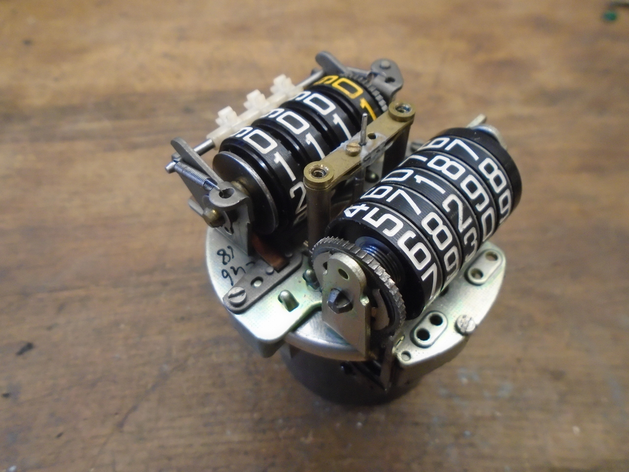
The speedometer also has a pair of odometers. On my
speedometer, the input spindle carries a brass worm gear, which
drives a pair of spur gears. Each spur gear has an
eccentric shaft that imparts a reciprocating motion to a pawl
arm. Each pawl arm bears against a ratchet wheel, and
advances the ratchet one tooth for each cycle. The ratchet
wheels drive the two odometers--the main odometer, and a
resettable trip odometer.
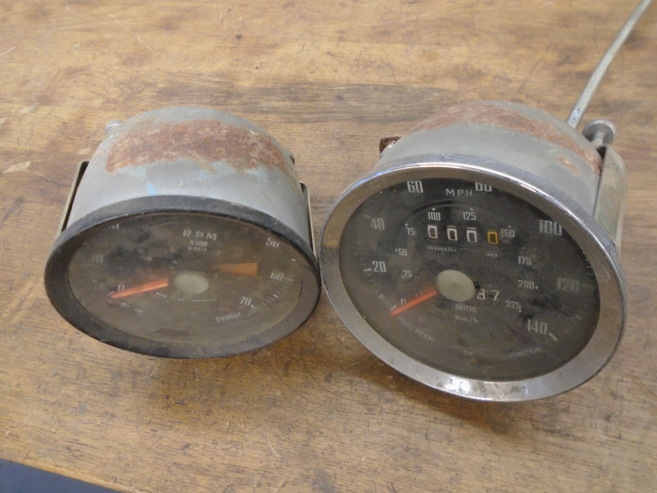
My instruments were pretty cruddy. They were also
mismatched, with the speedo having an incorrect chrome
bezel. Since the car has been in storage since 1980 or so,
it has to be a 70s replacement.
A simple test is to spin a small screwdriver inserted into the
input spindle. On the speedo, this resulted a little lurch
of the pointer, which is a good sign. On the tach, the
input spindle appeared to be seized, which is not a good sign.
I worked on the instruments in parallel, so the pictures that
follow might be from either the speedo or the tach.
The front bezel comes off bayonet-style, by twisting it until
the bezel fingers reach slots in the housing lip. It was
quite a bit easier to say it than to do it. The back of
the bezels had the remains of some dried-up sealing substance.
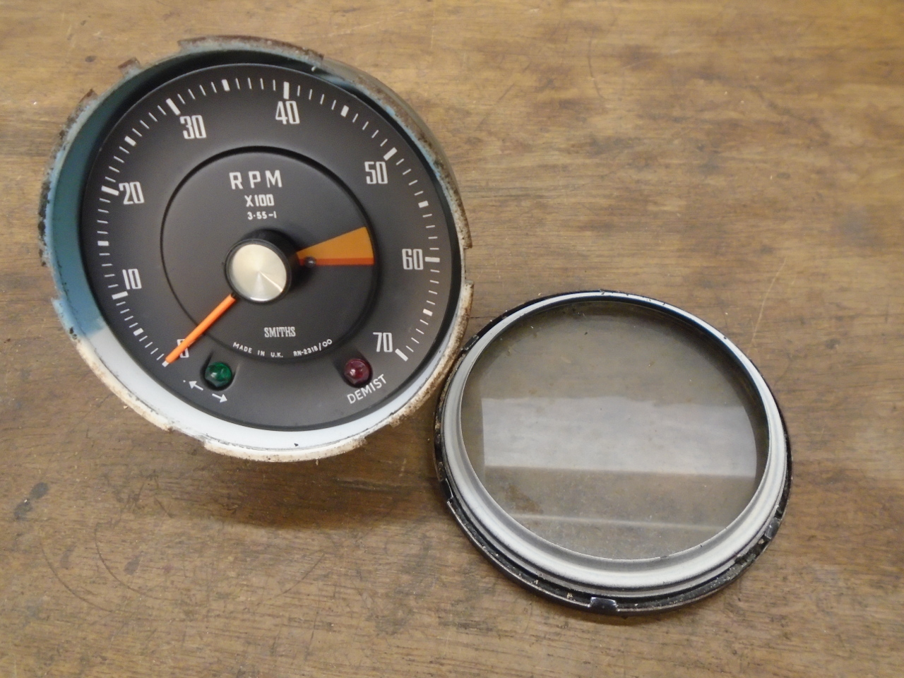
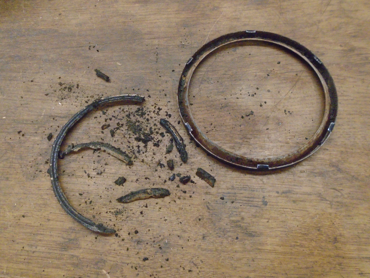
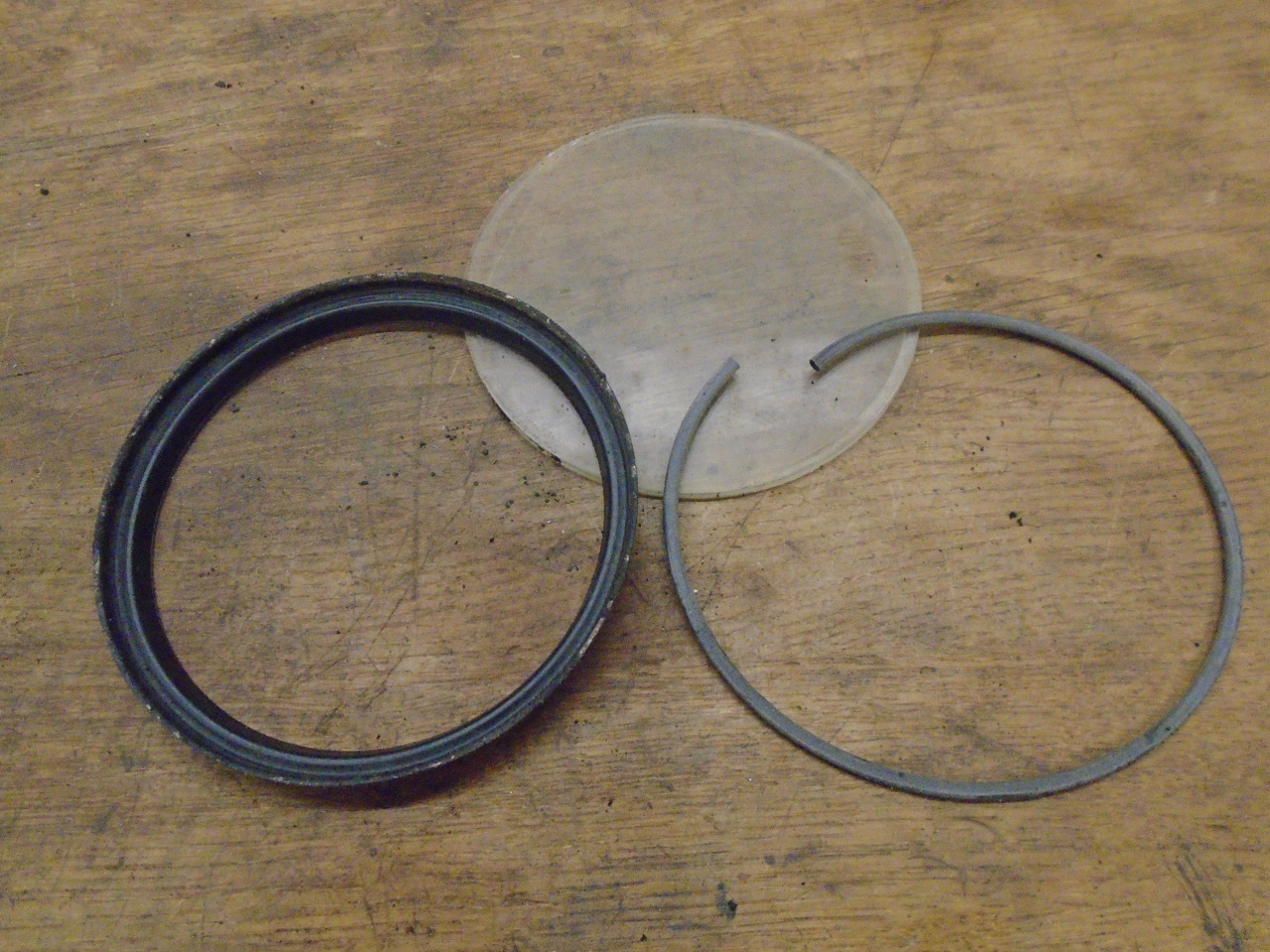
Inside, there is an inner bezel that holds the glass. A
thin hollow rubber tube served as a gasket between the glass and
inner bezel.
The guts of the instrument are freed up by two screws on the
back of the case.
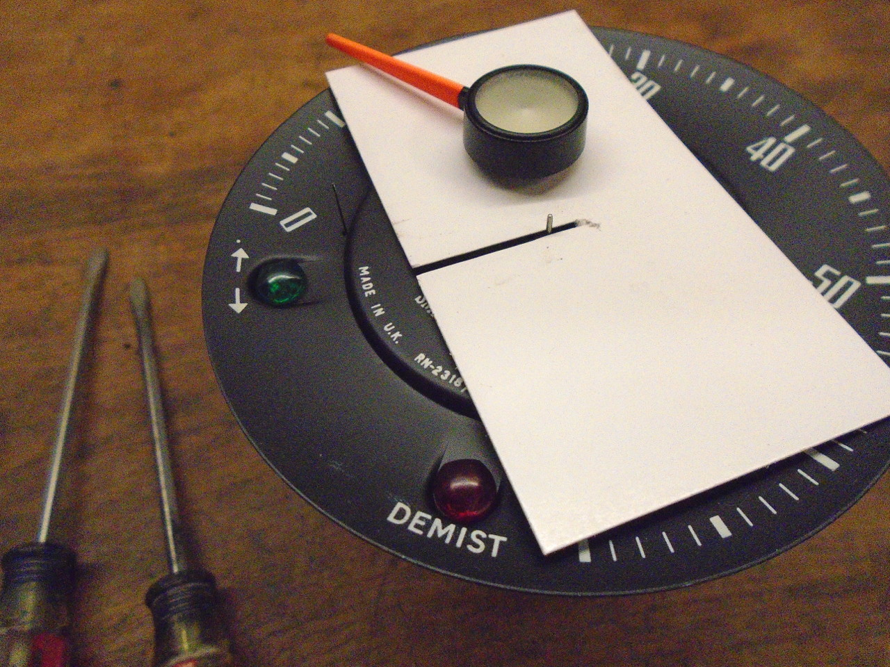
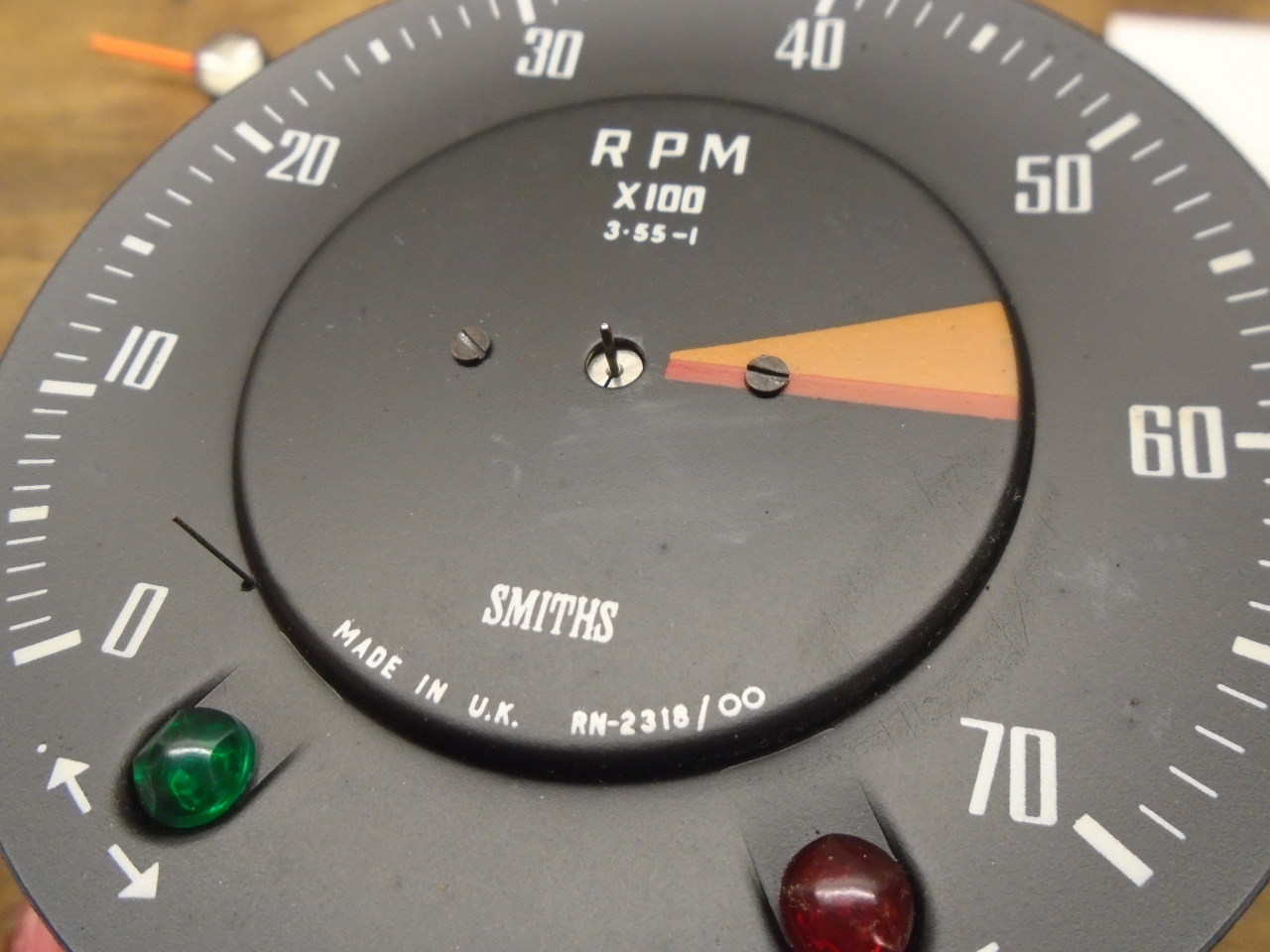
To really see much of the mechanism, the face had to come off,
but first the pointer. It is just a press fit on its
spindle. A couple of prying implements and some card stock
to protect the face did the job.
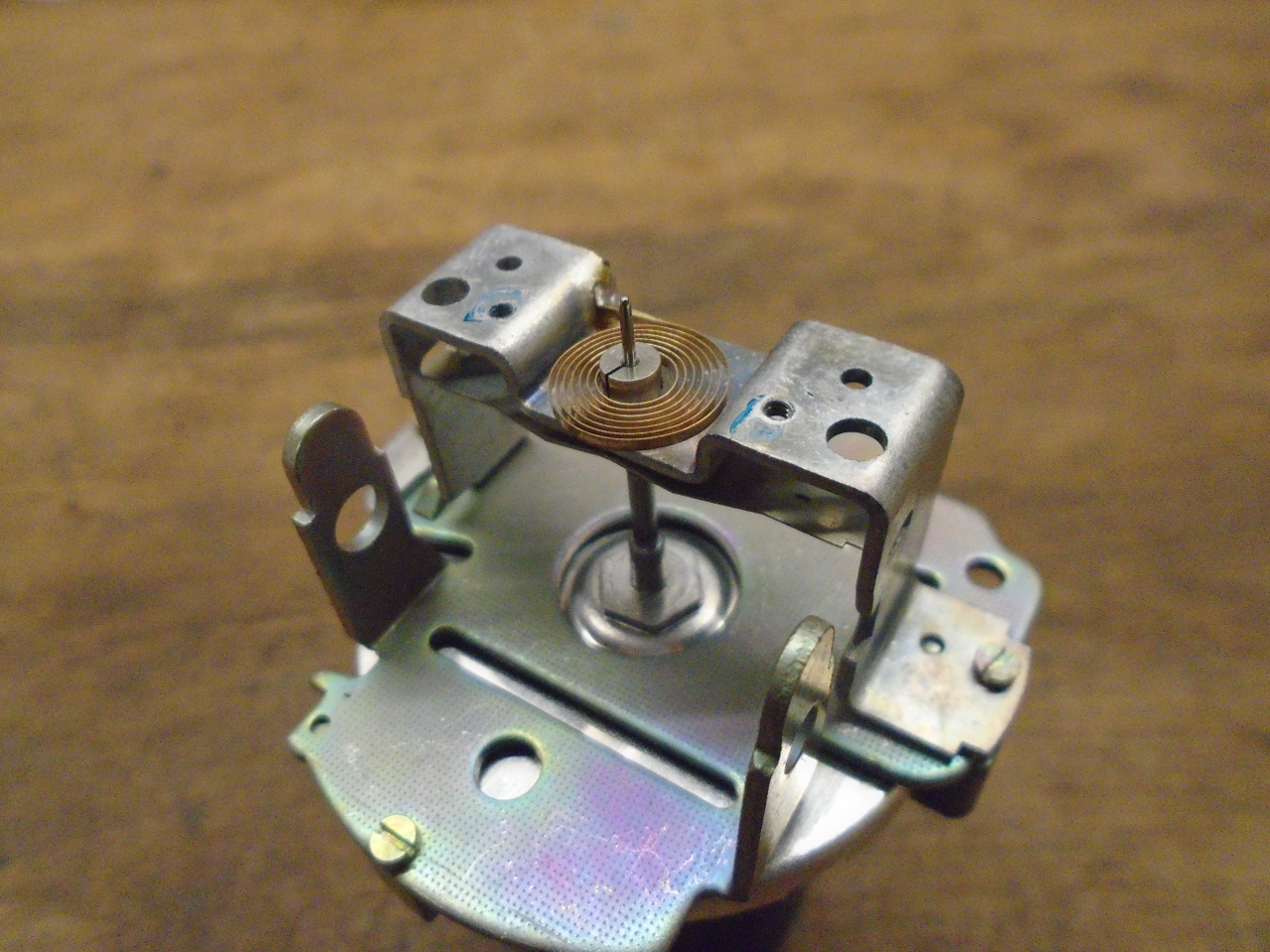
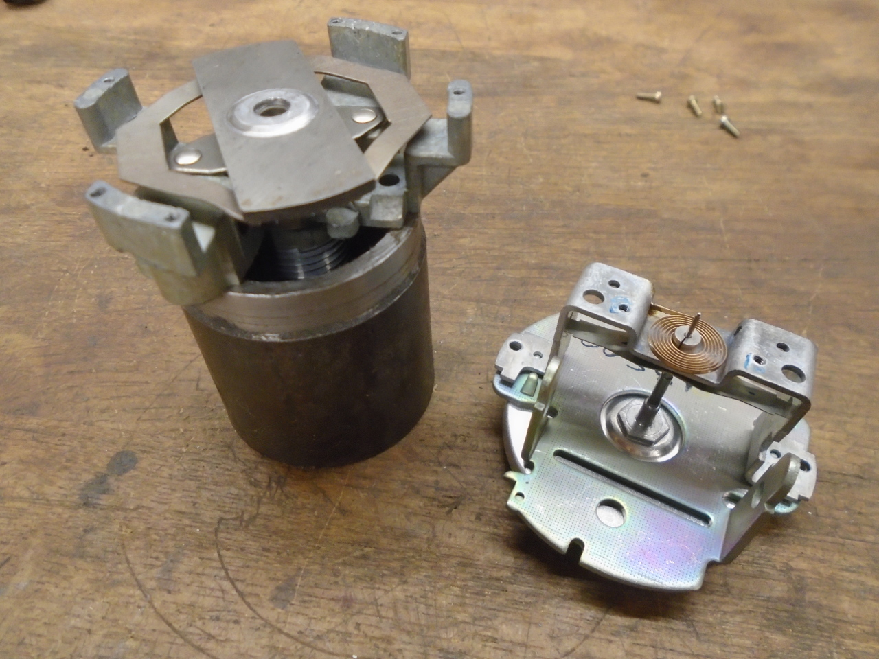
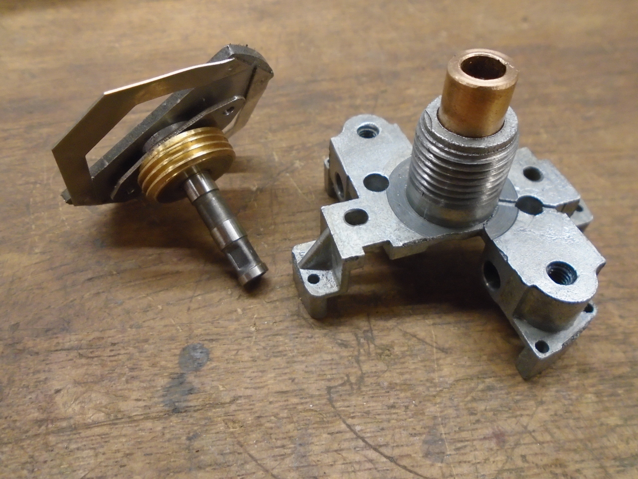
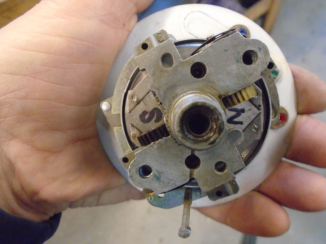
Then the mechanism can be separated into the magnet part and the
drag cup part. The magnet is that long piece on the top of
the assembly on the left. The cup is underneath the
assembly on the right. At this point, the magnet spindle
was still seized on the tach.
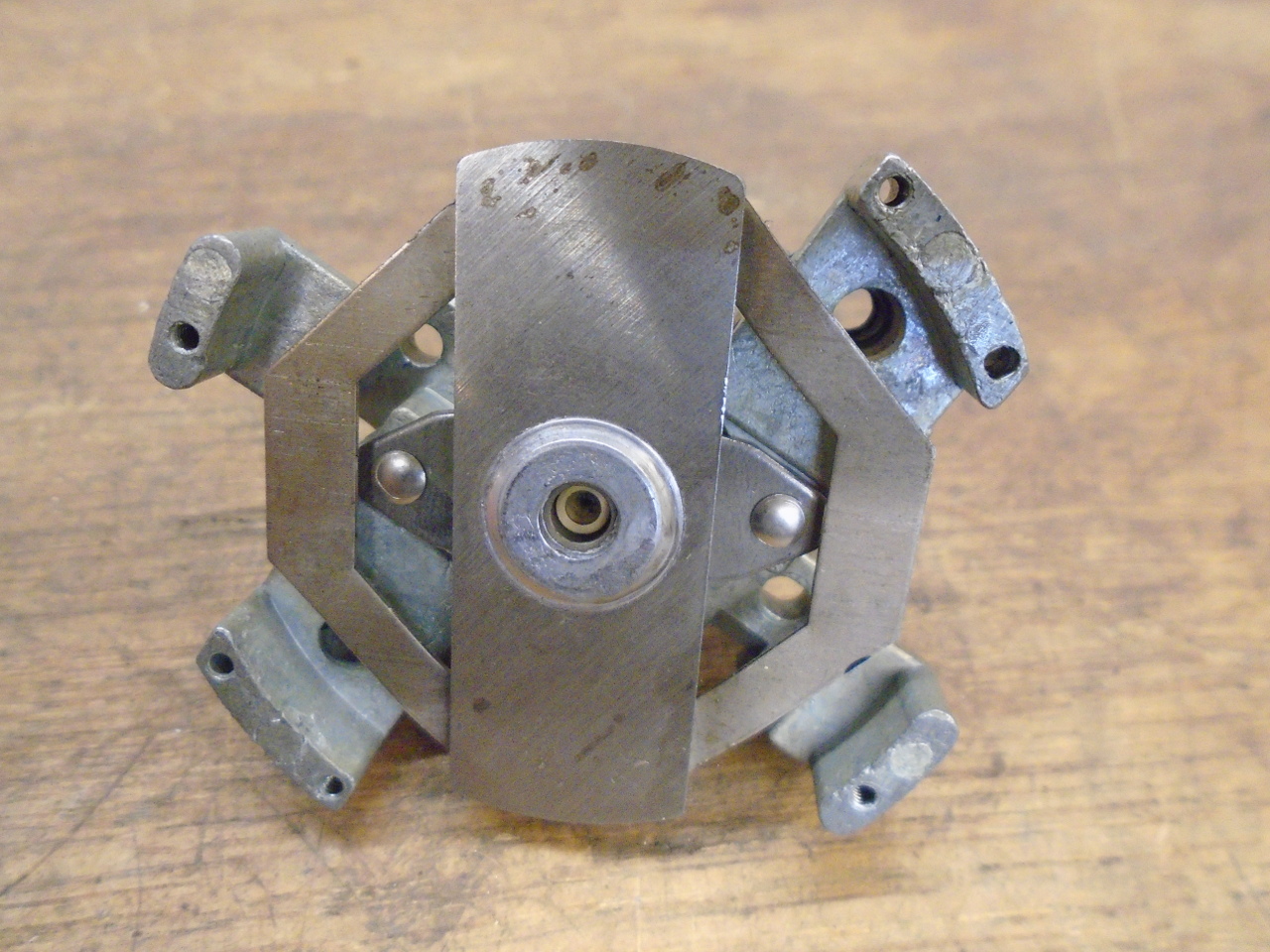
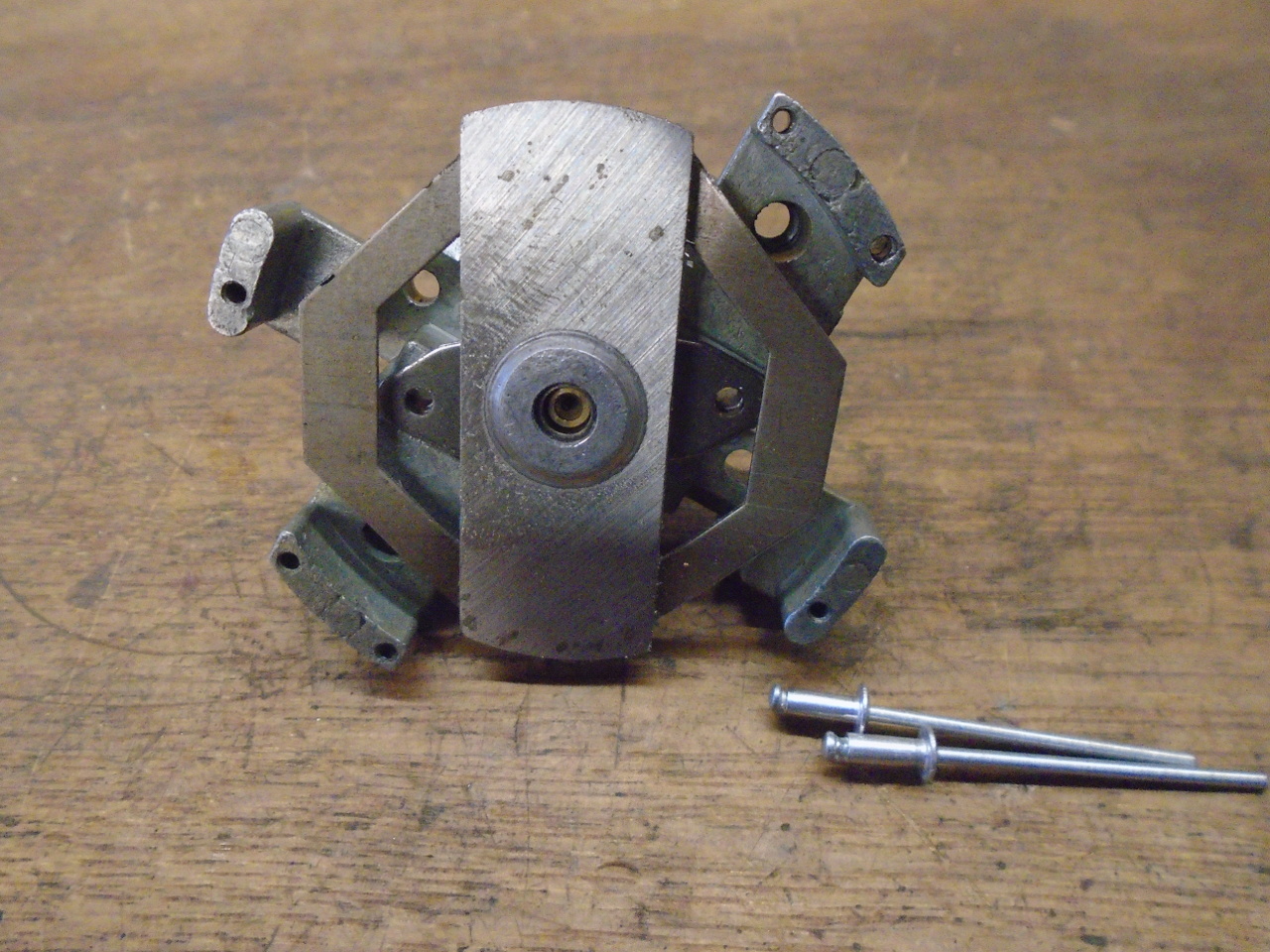
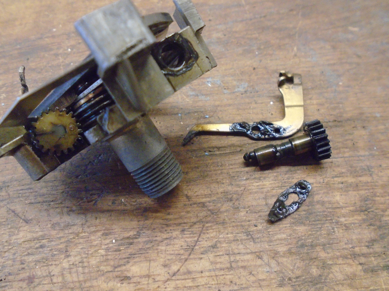
With some effort, I was able to get the magnet spindle turning,
but it was tight and rough. The spindle had to come
out. The magnet and spindle are held in the body by a
keeper and two rivets.
Drilling out the rivets freed the magnet. The tachometer
had the brass worm gear for the odometers, even though it is not
used for that. It just retains the spindle.
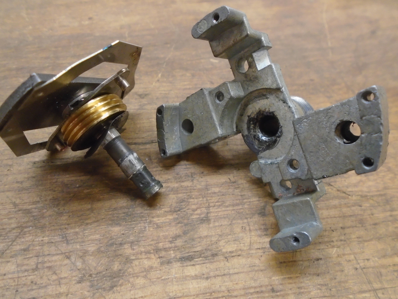
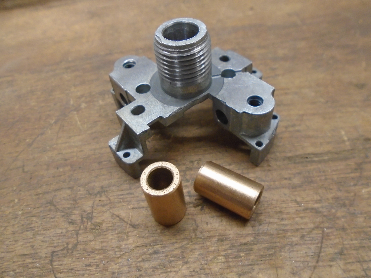
It looked to me that the problem was that the magnet spindle
just ran in the pot metal housing with no true bushing or
bearing. This surprised me a little, since the TR6 tach I
worked on a few years ago had a bronze bushing in that location.
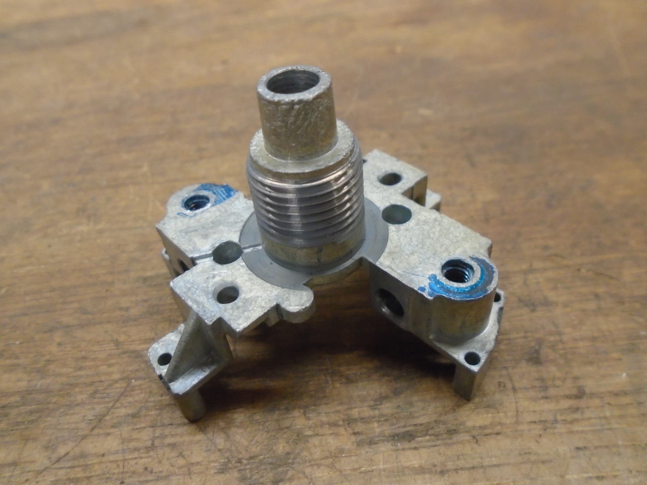
Since the bore was chowdered up pretty well, I decided I could
fix the tach and improve the design all at the same time.
I'd just put a bronze bushing in there.
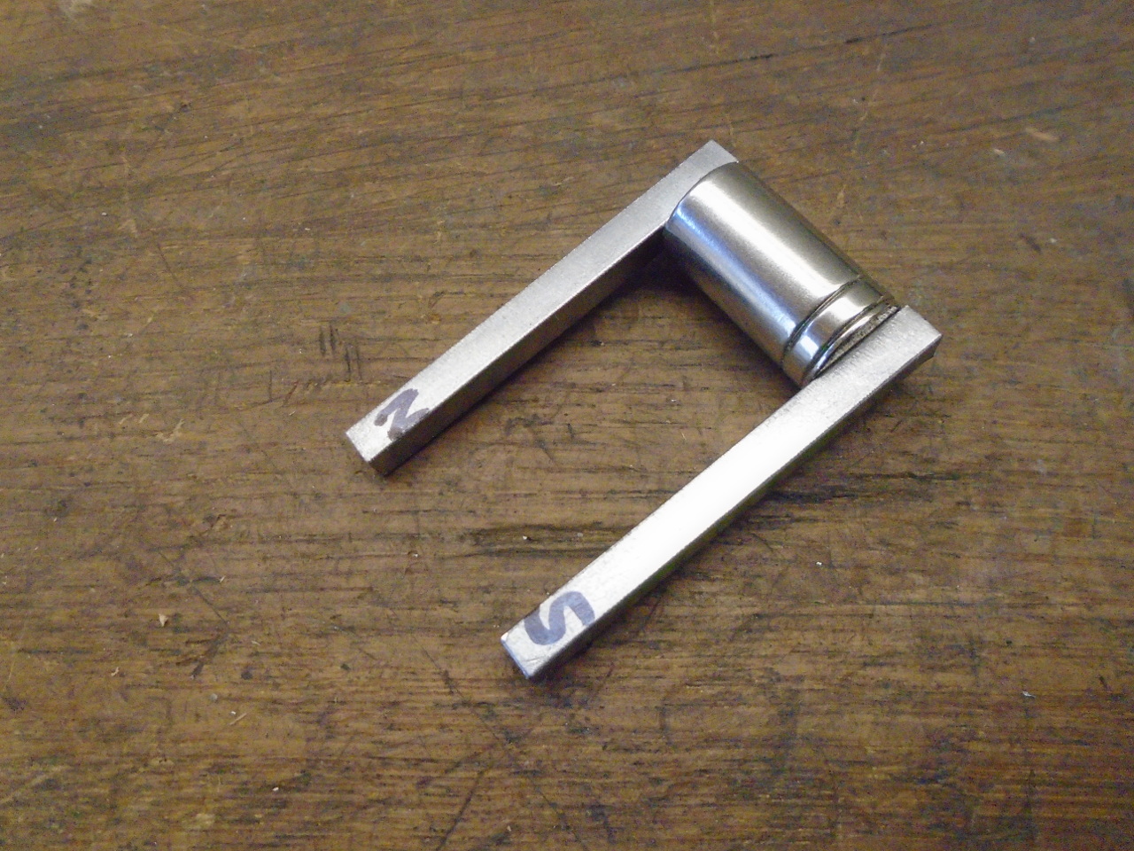
I didn't really have much choice on the size of the
bushing. In drilling out for the bushing, that little nose
protruding above the threads would pretty much be gone, but
since it looked like it was a necessary feature for the cable
seating, I'd have to replace it. The simplest way I could
see was to just let the new bushing be the nose.
This set the OD of the bushing at 3/8". The ID had to
match the spindle, which was 6 mm.
I didn't think I'd have much luck finding a bushing with a
metric ID and an Imperial OD, so I just ordered some 6mm x 10mm
Oilite bushes, and turned the OD down to 0.376" to be a tight
fit in the reamed 0.375" bore. I couldn't find the length,
so I just pushed in two, and trimmed the excess.
Then inserted the magnet spindle with a nice coating of light
oil, and riveted it back in place.
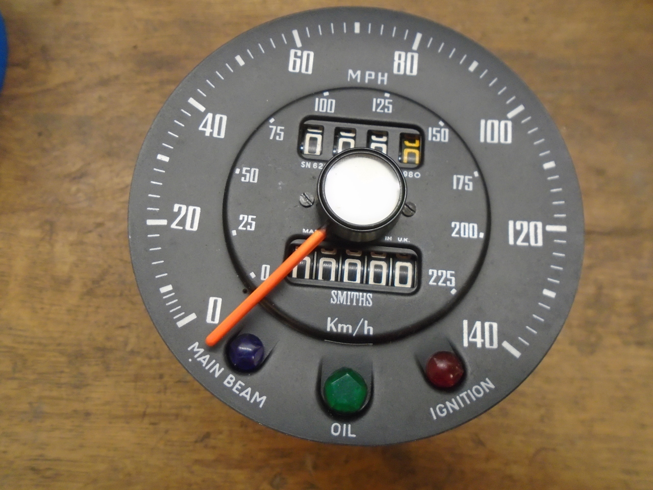
Then put everything back together. The pointer is pressed
on so that when at rest, it aligns with a small dot below the
zero on the face. Then the pointer stop is retracted so
that the pointer can be rotated past it. This provides the
small amount of preload to the spring so the pointer bears
lightly against the stop at rest.
To bring the speedometer to this point was a little
different. The internals of the speedometer work the same
as the tach, but the added odometers dominate the construction.
On checking the rotation of the input spindle, it felt very
smooth and free, except very occasionally, I could feel a
mechanical catch in it. It seemed to be related to one of
the odometer pawl gears, so I took all of those parts out for
cleaning and inspection. They had a lot of grease on them
for some reason.
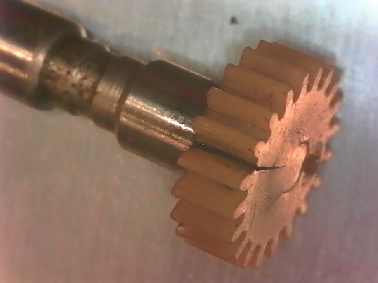
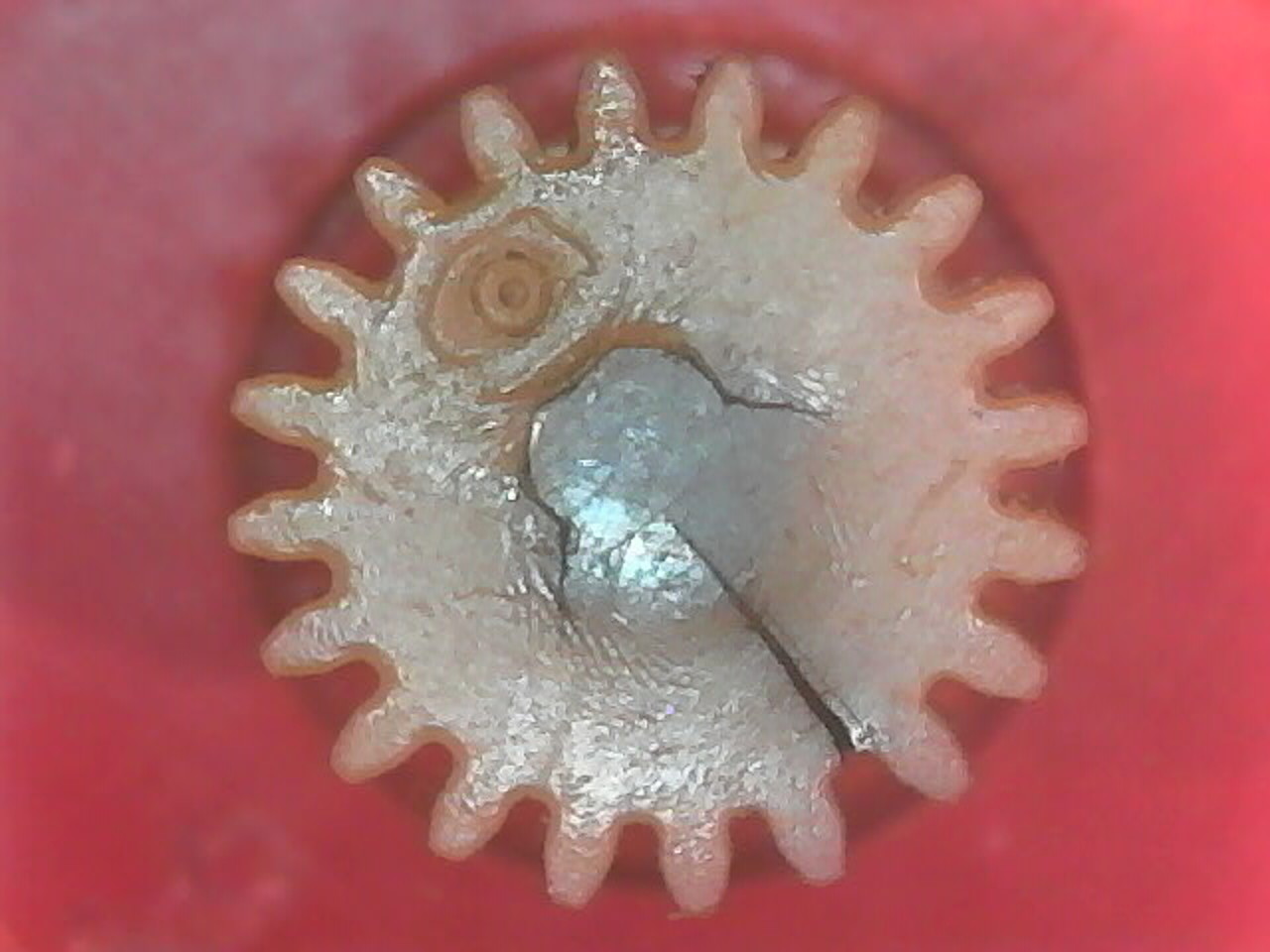
I finally traced the problem to one of the gears that had a
split in it. The gear was still firmly attached to its
shaft, but the split spread two of the teeth apart slightly, so
the mesh would bind in that area. Without much hope of
finding a good replacement part easily, I just reshaped the
teeth slightly with a file so they still meshed, but didn't
bind.
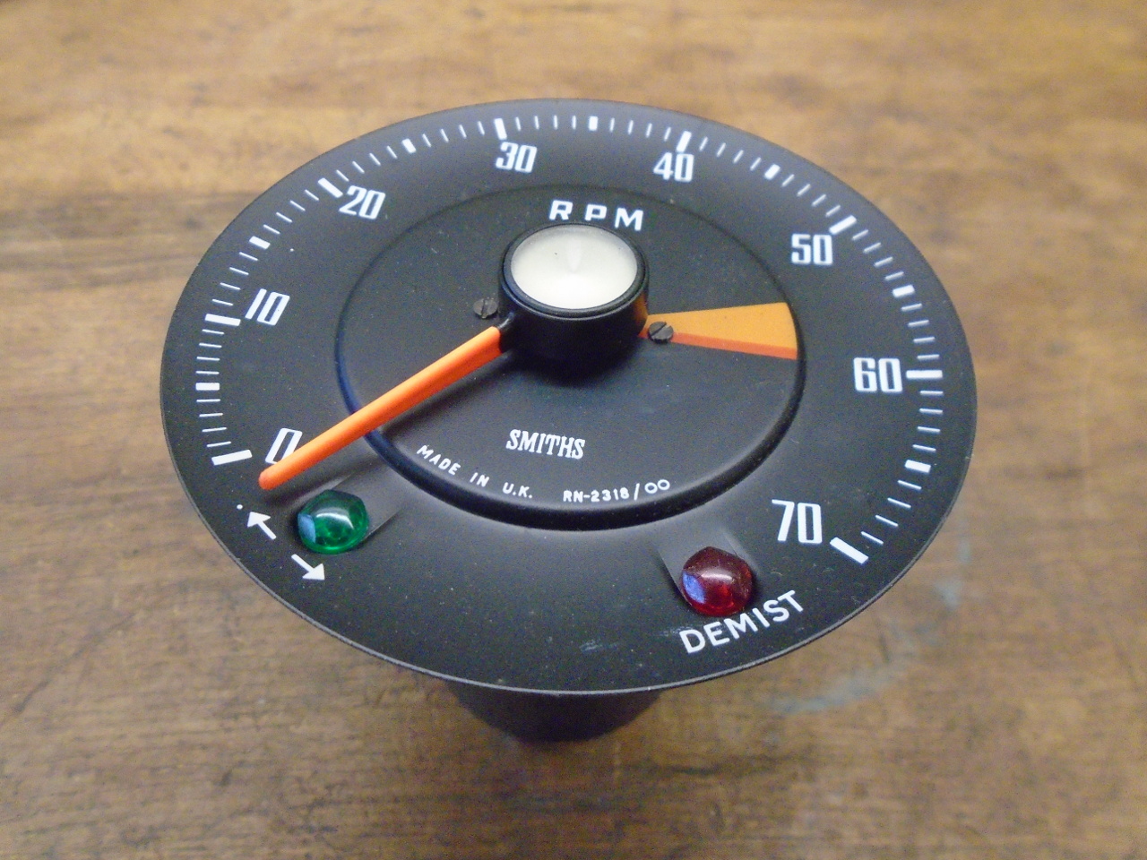
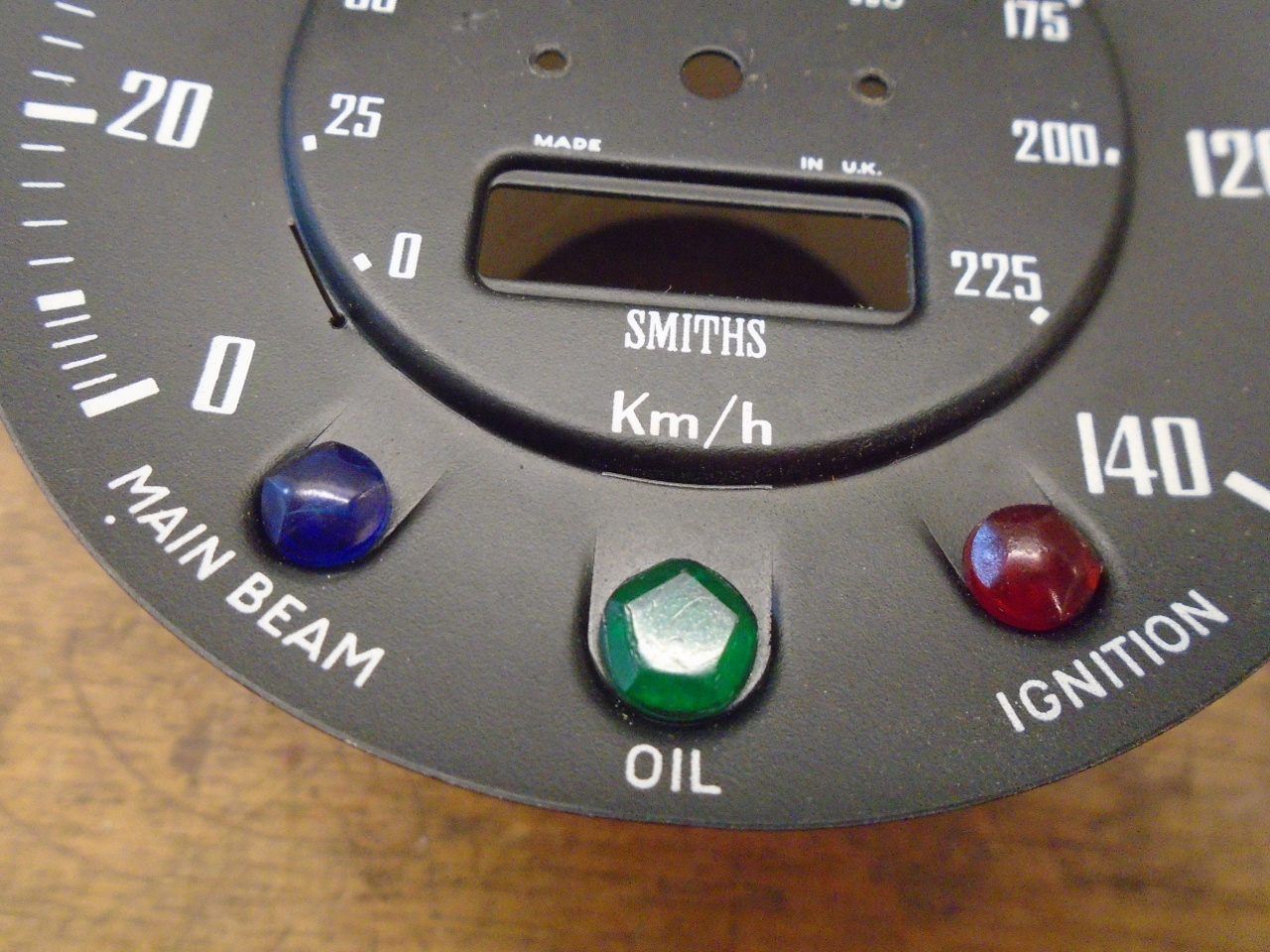
There was also the little green jewel for the oil light that I
found loose in the case. I was apparently just glued in
place. I put it back where it belonged, and staked the
back with a hot soldering iron.

Then there was the issue of the mileage reading on the main
odometer. Given that the speedometer is not original, plus
the fact that it was not even working for most of the time I
drove the car, the reading has no relevance to this car.
Also given that the car will be for many practical purposes a
new car when finished, I justified my desire to return the main
odometer to zero.
One way to zero an odometer is to take it apart and reassemble
it with all zeros showing. I did this for my TR6, and
found the process to be harrowing. I wanted an easier
way. I could spin the ratchet wheel by hand either forward
or backward, and change the reading by about 32 miles in a
minute. I did the math, and decided this was maybe doable,
but not practical. I finally fiddled with it and
inadvertently stumbled on a way to get individual wheels to turn
independently. I can't explain how I did it because I
really don't know.
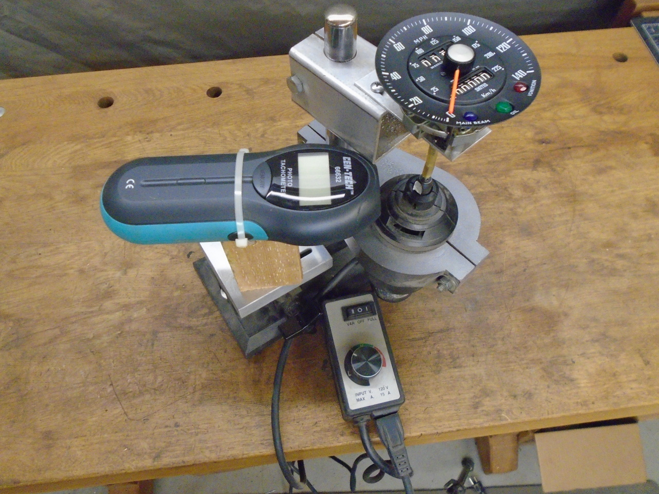
So, then with both instruments apparently working smoothly, I
wanted to have some confidence in their accuracy. This is
a calibration rig I made years ago when I did my motorcycle
instruments, and used again for the TR6. It is basically a
universal motor (it is a Craftsman chainsaw sharpener motor,
modified to run backwards) on a speed controller, an optical
digital tachometer to read the speed of the motor, and a stand
to hold the instrument and everything else in the right
relationship. The motor drives the instrument spindle
directly.
I did the speedometer first. Speedos of this type will
normally have a number printed somewhere on the dial face that
indicates how many turns of the input spindle it will take to
rack up one mile on the odometers. A little thought and
arithmetic will show that this is also the input RPM that should
indicate 60 MPH on the dial. On my speedo, this number was
980.
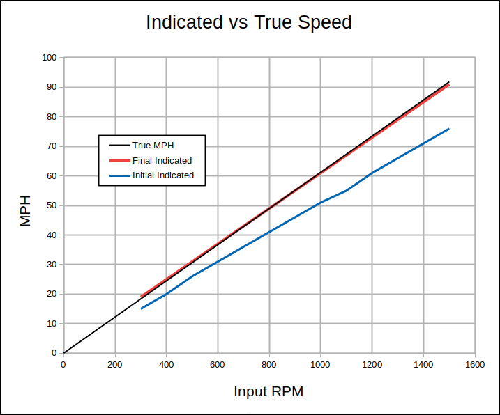
So, by taking readings at various input RPMs, it is easy to
graph the results and compare to what the readings should be.
The black line in the graph below shows the perfect relationship
between input RPM and dial reading. The blue line is what
my speedometer initially showed. It was around 18% low
across the range.
This is what is known as a "slope error". The other common
kind of error is a so-called "offset error", where the error is
a constant number across the range. The fact that the blue
line above is pointed towards zero is an indication that there
is little offset error here.
The slope of the line is determined in this kind of instrument
by two things: the strength of the spring, and the
strength of the magnet. Either of these can be manipulated
to change the slope. I chose the magnet.
A stronger magnet will steepen the slope. Magnets can be
strengthened by bringing a stronger magnet in close
proximity. I stacked some rare earth magnets and added
some steel extension pieces. I hoped the extensions would
allow me to contact the instrument magnet without taking
everything apart again.
It's also important to know the polarity of both magnets.
I found that by using a magnetic comapass.
It seemed to work OK. In fact, it worked so well that
after the first "strengthening" attempt, the speedometer was
reading almost 90 MPH when it should have read 60. OK, a
little too much of a good thing. Luckily, reversing the
polarity will reduce the strength of the weaker magnet.
It took a few iterations, but I was able, partly by luck, to get
the red line in the graph above. The speedo read about 3%
low at the high end and slightly high at the low end. I
would have been very happy with 5%.
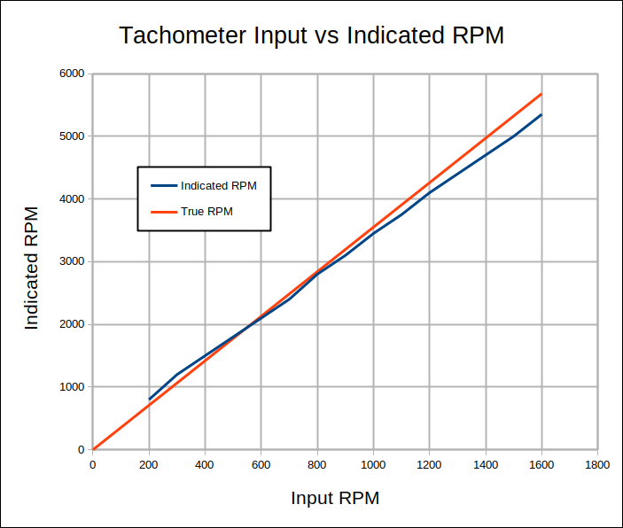
I repeated the process for the tach, and the results are shown
below. Since I don't really rely on the tach that much, I
was satisfied with this.
OK, so I was pretty happy with the way the instruments were
working. All that was left was to button them up. I
blasted the cases...
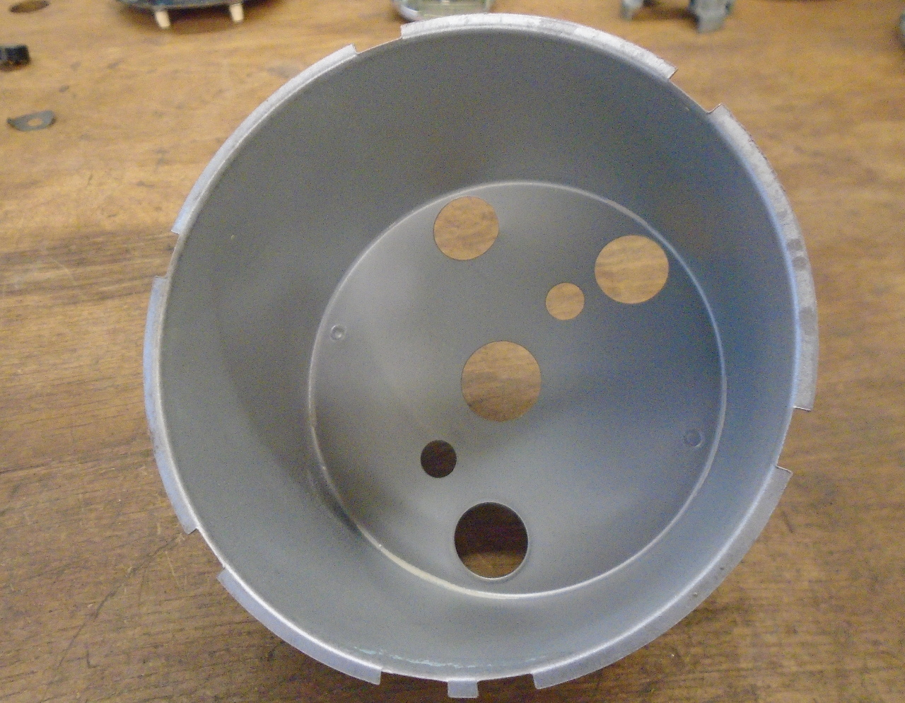
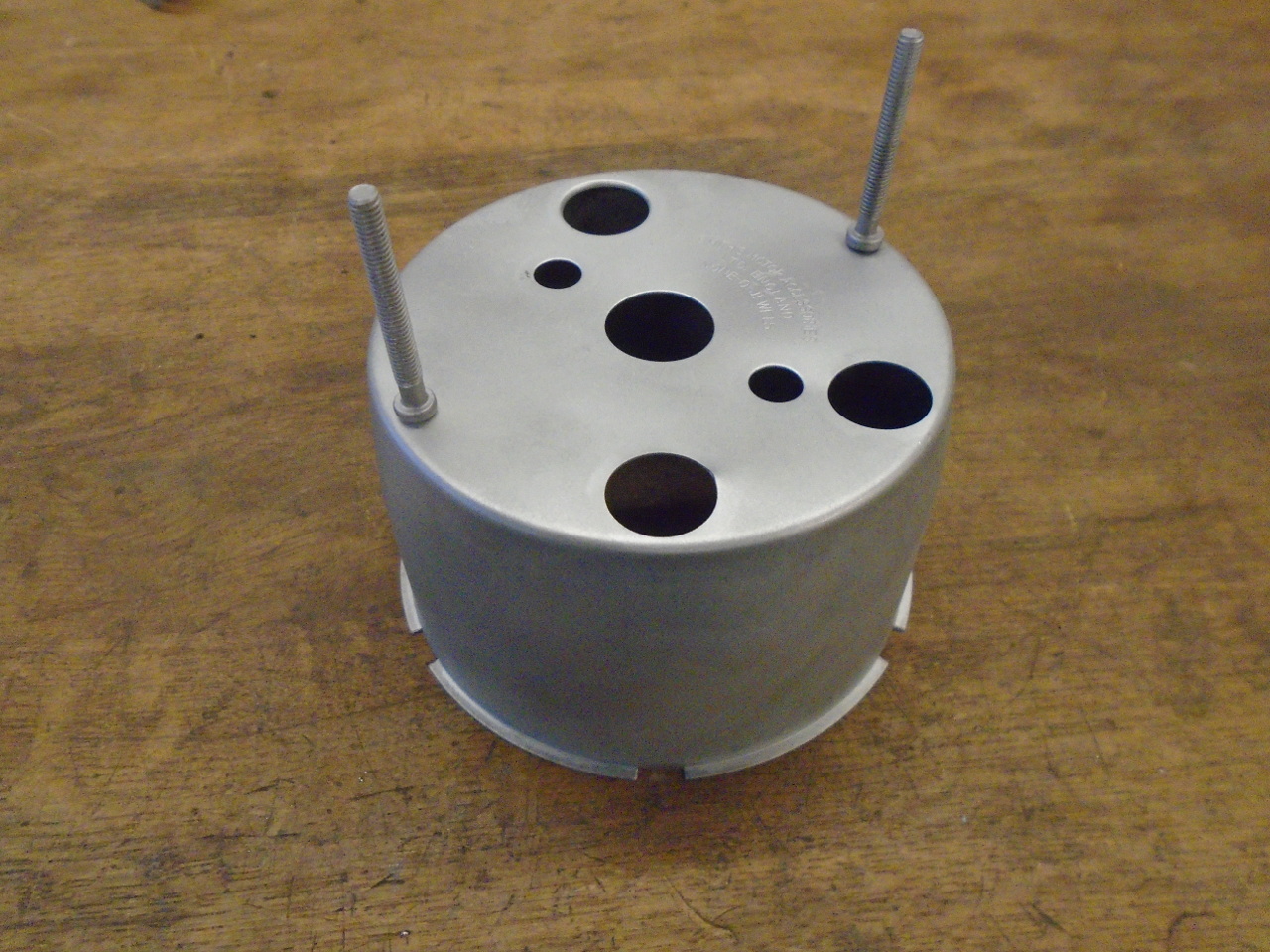
...powder coated the outside...

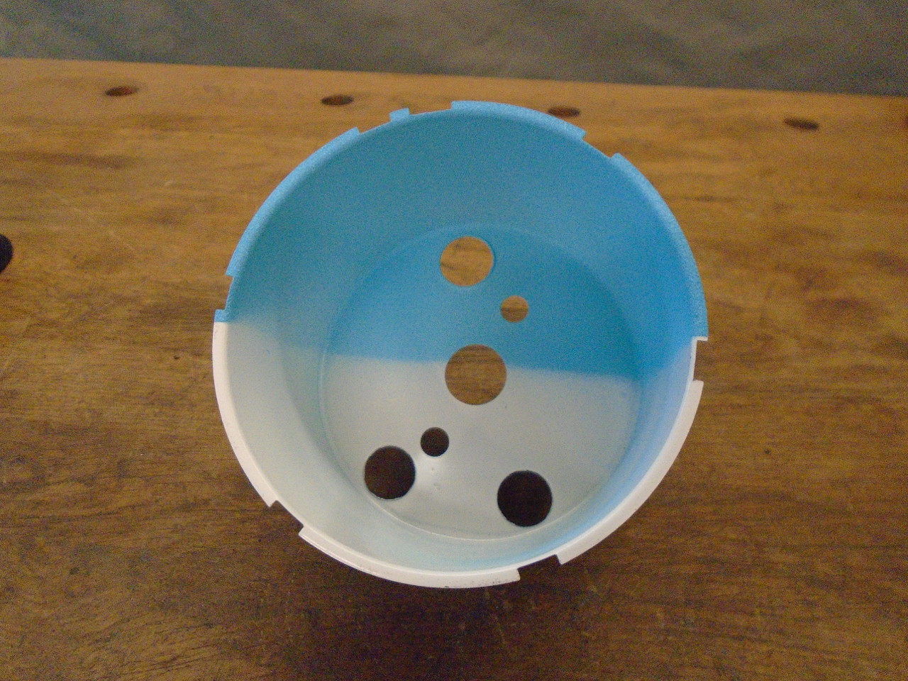
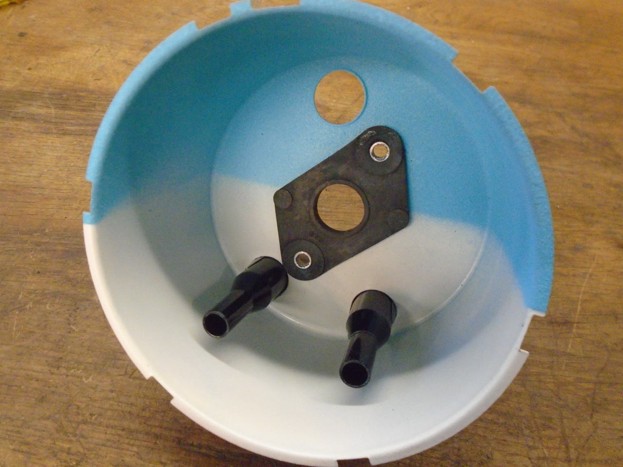
...and painted the inside. I matched the blue color the
best I could. I think it was an attempt to even out the
light intensity around the perimeter of the face.
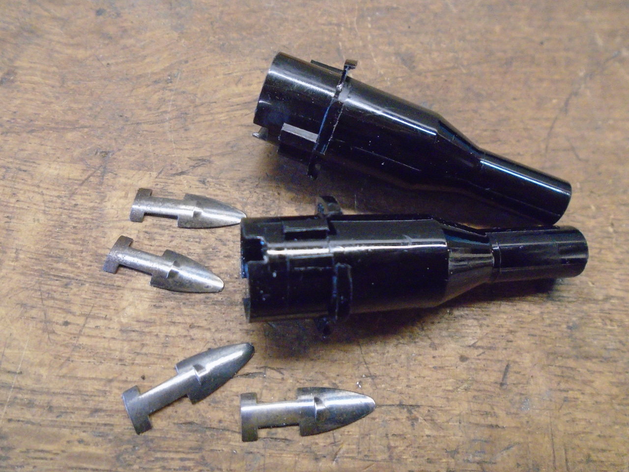
Added the little plastic tubes that isolate the indicator lights
from the face lighting, and the rubber isolator for the
attachment points. The original isolator was usable, but
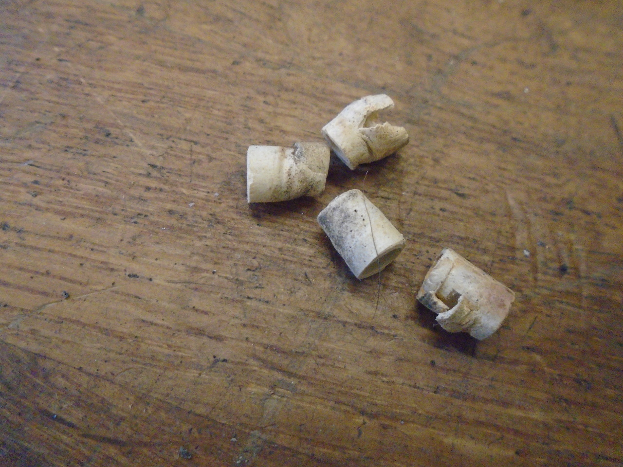
barely. The third picture shows the little white rubber
sleeve thingies that were on the ends of the light tubes,
apparently to bridge the gap to the jewels. I found two of
the four had buckled over and were blocking light rather than
guiding it. I didn't replace them.
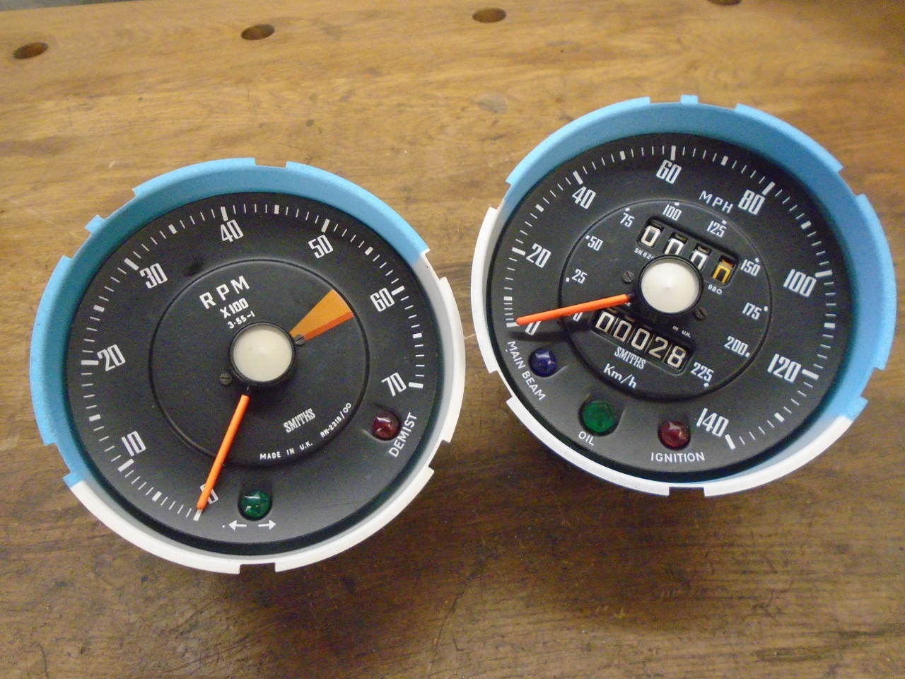
Brought the guts home. The 28 miles on the speedo was what
it took to get the calibration rig set up and the speedo
adjusted right.
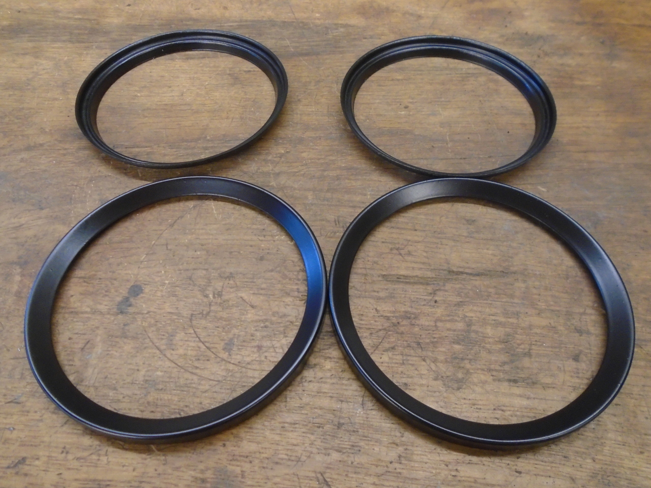
Then prepped the inner and outer bezels.
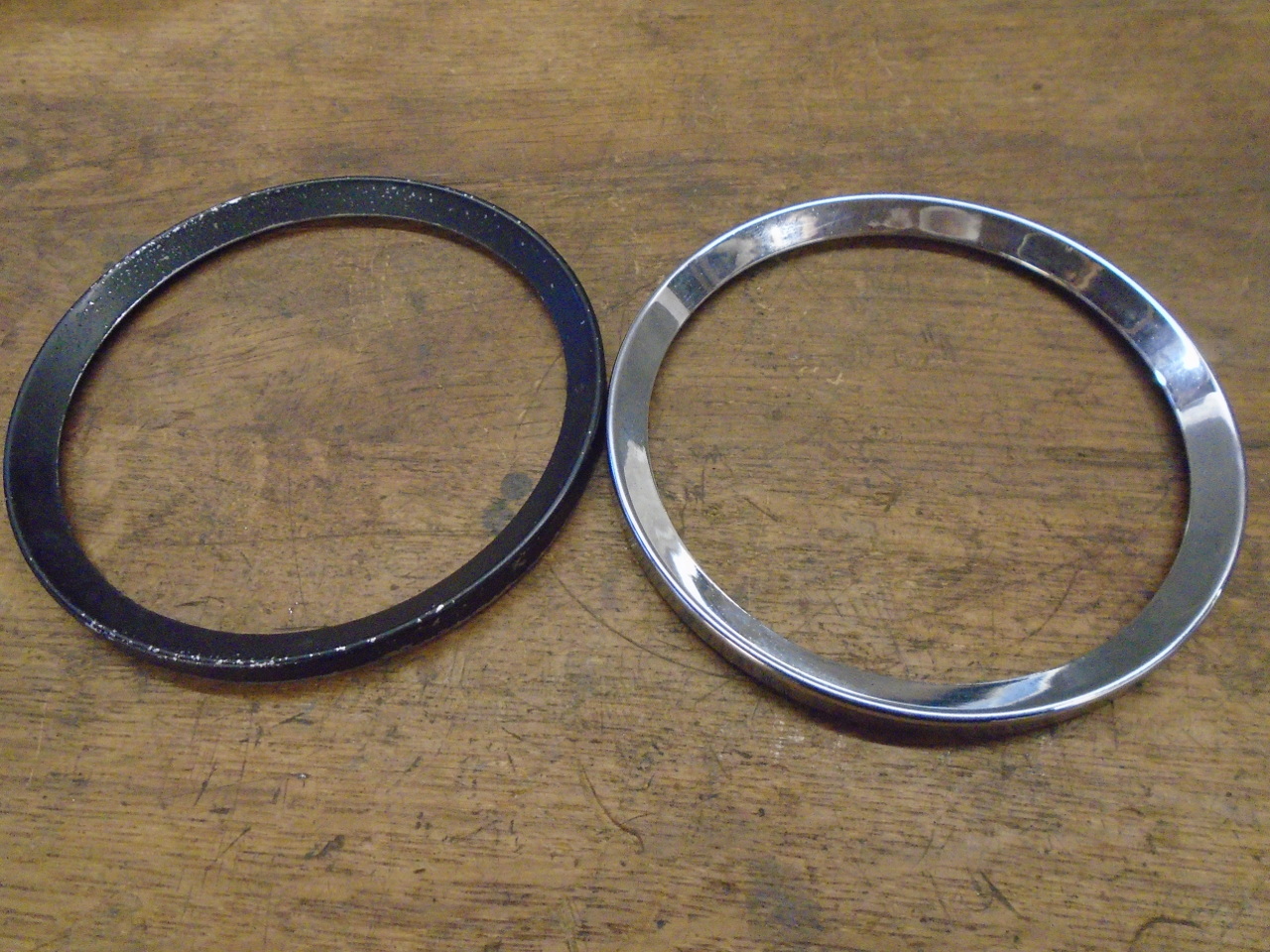
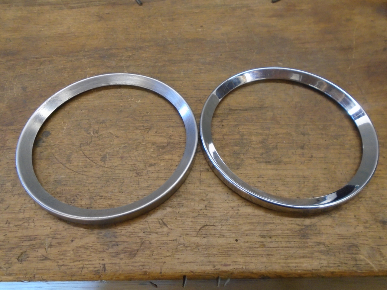
Inner bezels were painted, outer ones were powder coated for
durability.
This stuff is O ring cord stock It is silicone, and pretty
soft. I got it to see if it could replace the seals on
either side of the glass.
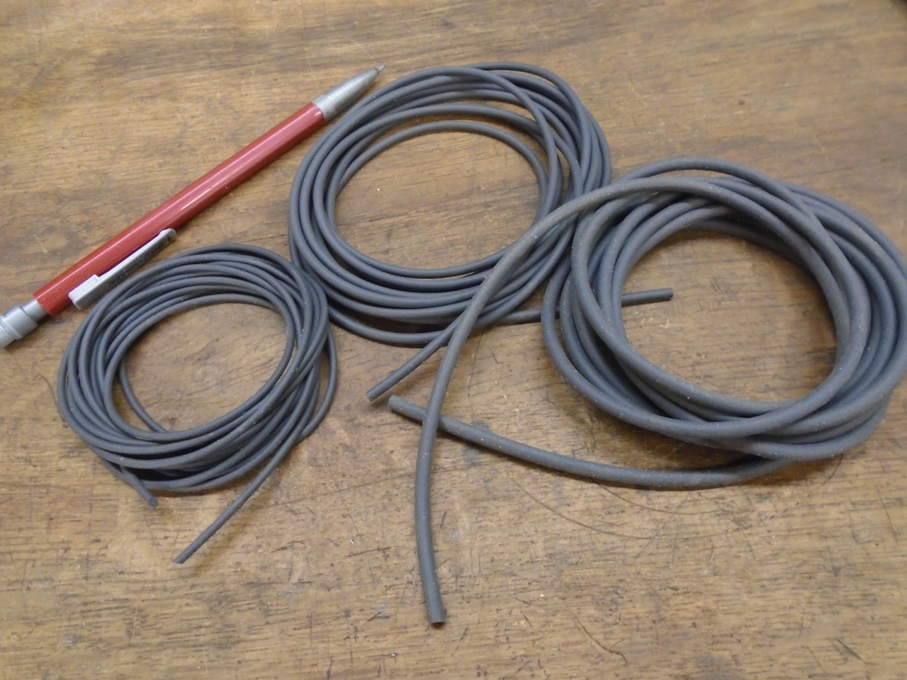
The smallest size worked well for the underside of the glass,
while the largest made a good seal under the outer bezel.
I wiped it with a thin smear of petroleum jelly to make twisting
the bezel on a little easier.
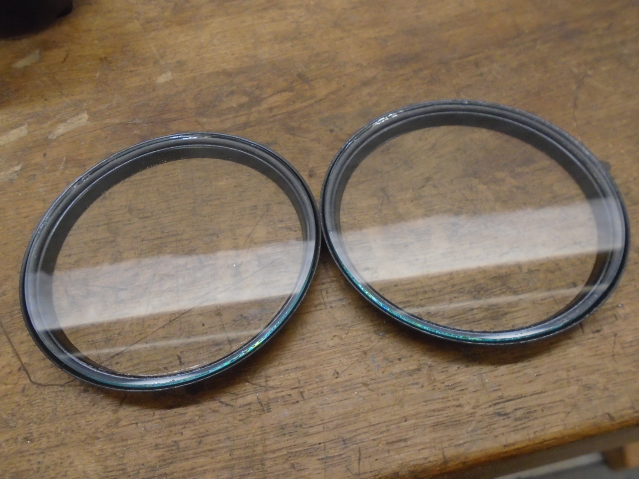
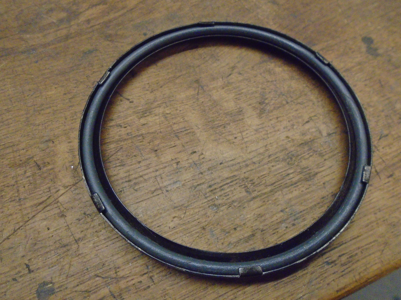
After all this, I think they will do.
This one was finicky work. I enjoy it to a point, but I'm
ready to move on to something that doesn't require tweezers.
The only cost was for the bushings, the cord stock, and some
consumables. Certainly under $20.
Comments to Ed at: mailto:elhollin1@yahoo.com
To my other GT6
pages