To my other GT6
pages
January 31, 2020
Distributor
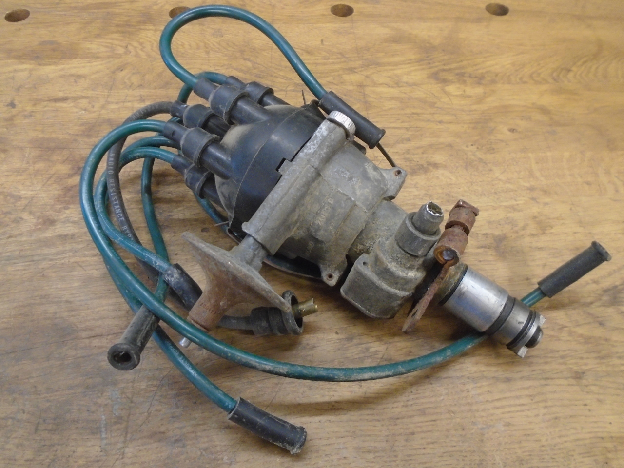
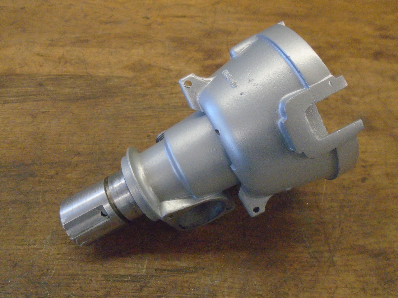
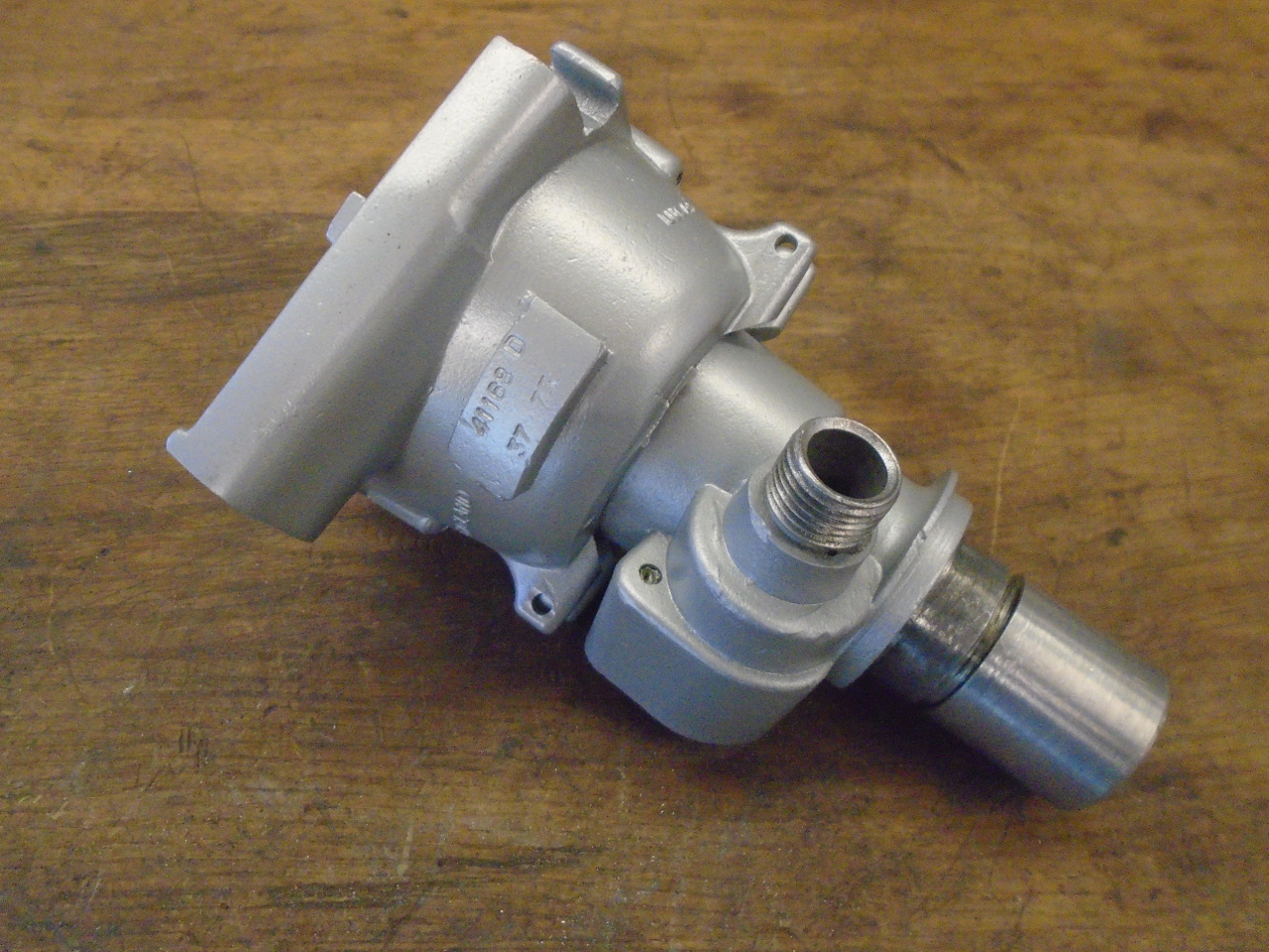
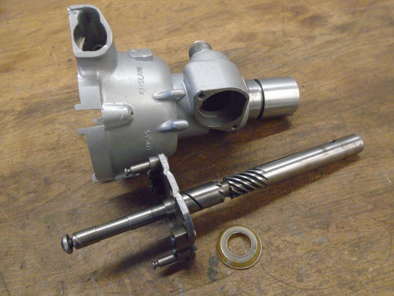
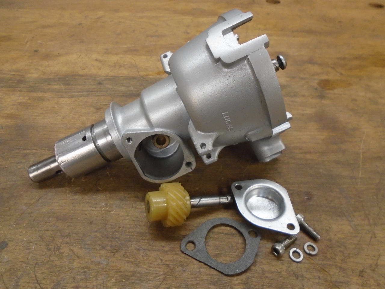
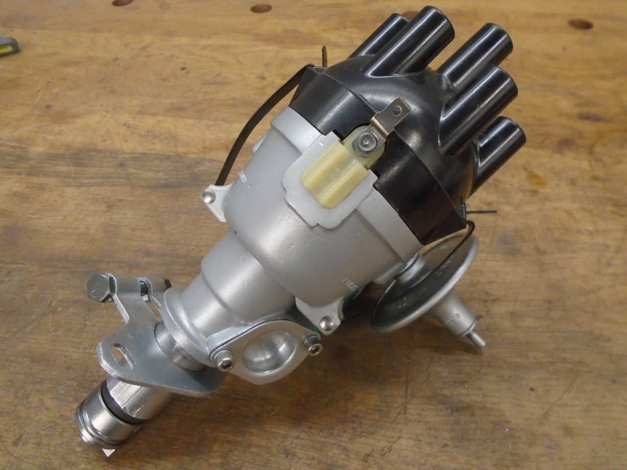
Lucas made distributors that were used in a wide
range of cars, trucks, and other equipment of the era. My
GT6 had the ubiquitous 22D distributor. This is a pretty
ordinary distributor, which includes provisions for both
centrifugal and vacuum advance, and also provides a take-off for
a mechanical tachometer. With a date code of 37th week of
'73, it wasn't original, but an early replacement. It was
corroded and dirty, and had some visible broken bits. I
hoped the insides were in better shape.
Disassembly went OK until I got to the cover for the tachometer
drive gear. Oddly, the two screws were different
sizes. The bigger one came out alright, but the smaller
one came to a tragic end, its head twisted off its body.
The reason for the mismatched screws came back to me
slowly. I had this distributor apart once before--a minor
refresh back in the 80s. One of the screws broke back
then, and I had to re-tap the hole for a larger 8-32
screw. It was time for the encore.
I wanted to make sure I could fix the broken screw before I
spent any more time on this distributor. I decided to try
drilling the remains out. The main challenge in drilling
out a small screw like this is getting the drill bit centered on
the screw. If the bit wanders off the steel screw and into
the softer body metal, it will just shift the hole position at
best, and could make things worse by leaving a broken drill bit
lodged in the body.
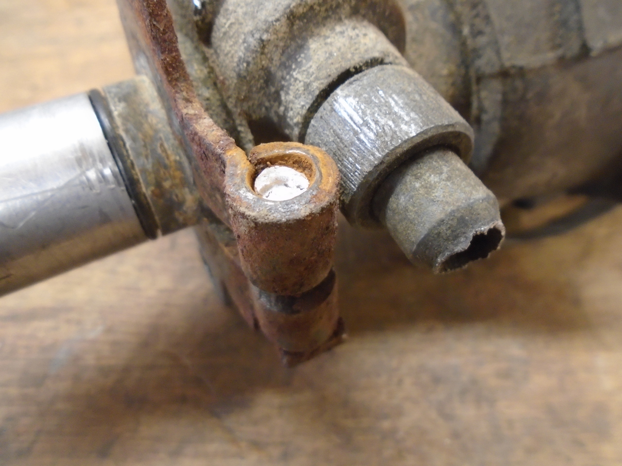
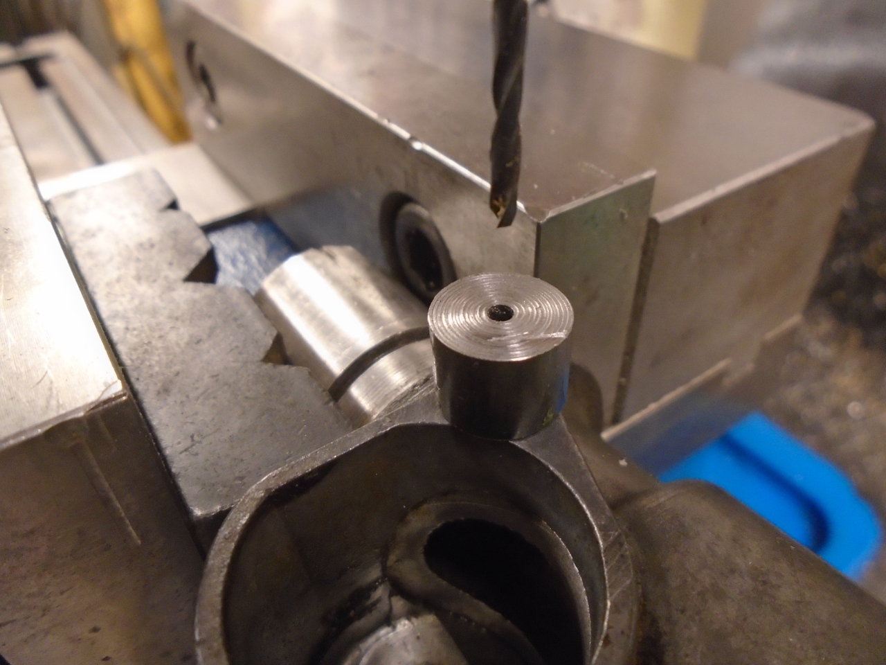
The screw was broken off just a little proud of the body
surface. I made a little drill guide with a recess on the
bottom side that would just fit the screw stub. This
centered a small pilot hole that would guide a larger bit to
remove the screw and size the hole for an 8-32 tap. So,
after 30-some years, the holes match again.
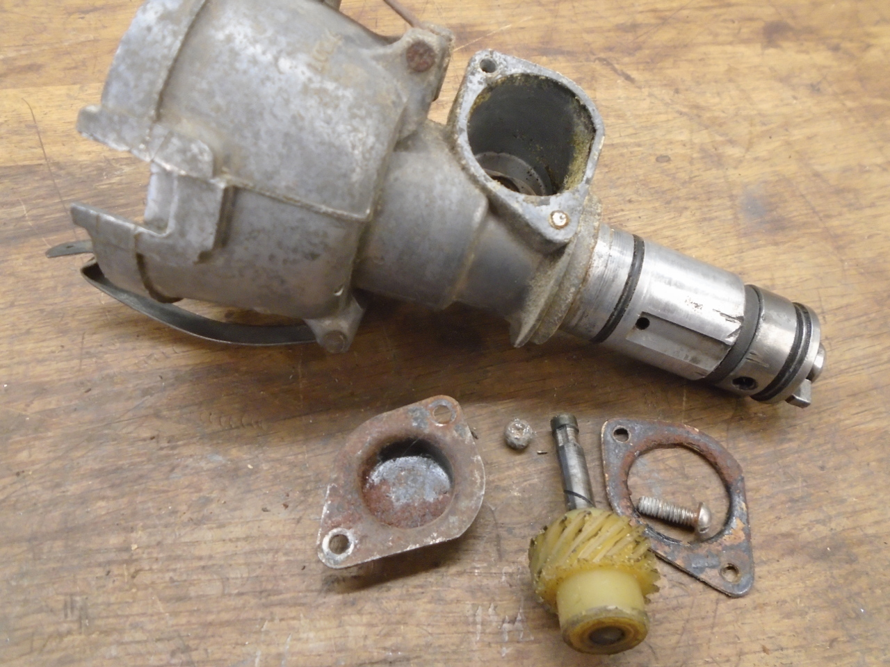
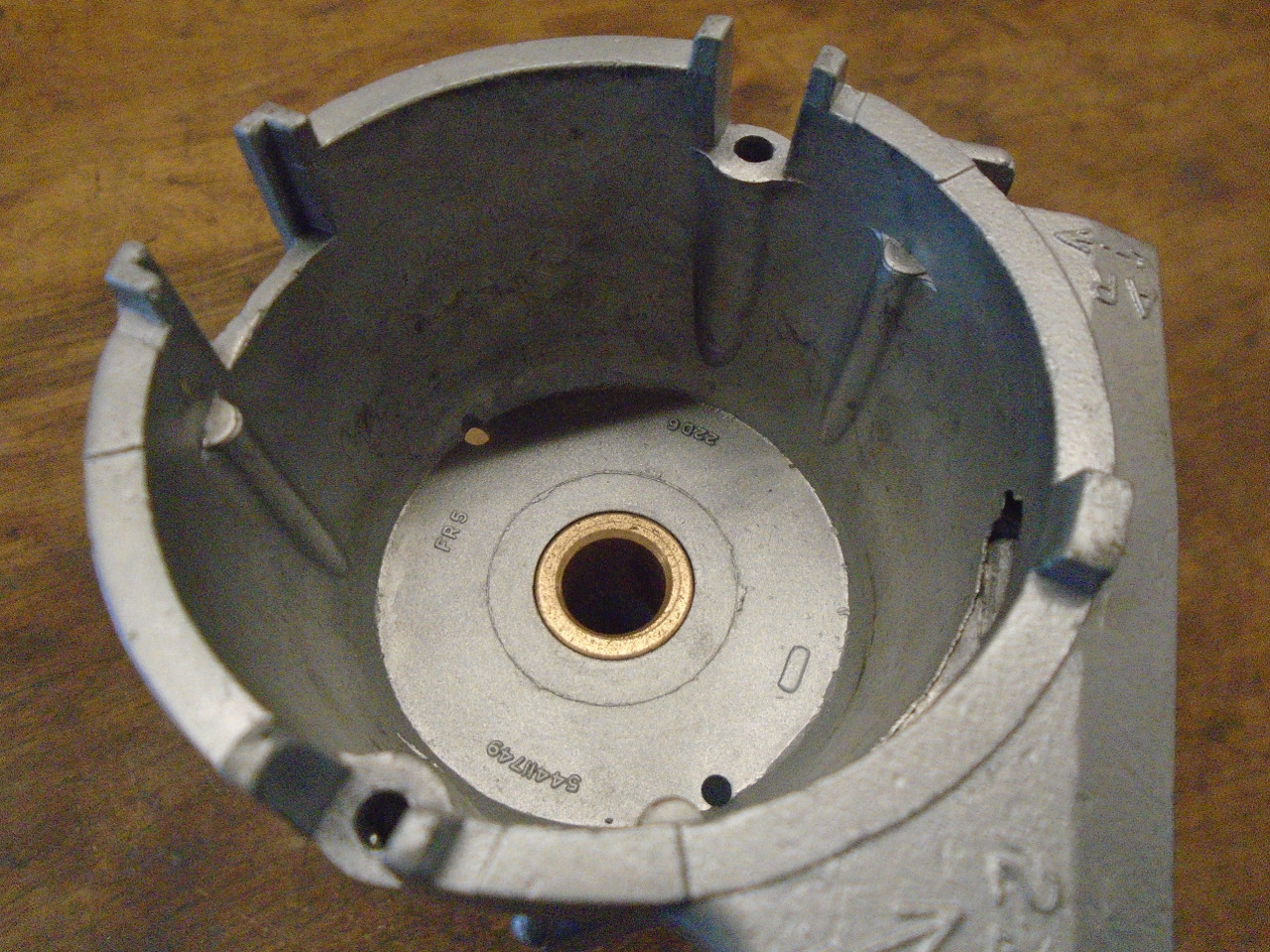
So. with that tragedy averted, I proceeded to clean up the
body. During disassembly I tried to evaluate the condition
of the spindle bushings. I concluded that they weren't
terrible, but I was aiming for something a notch or two above
"not terrible". So, out came the spindle bushes. And
the tach drive bush, just because.
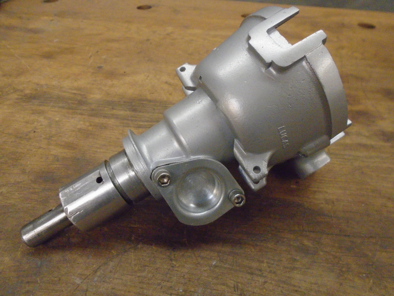
The bare body got a light blast, which made it look a lot
better.
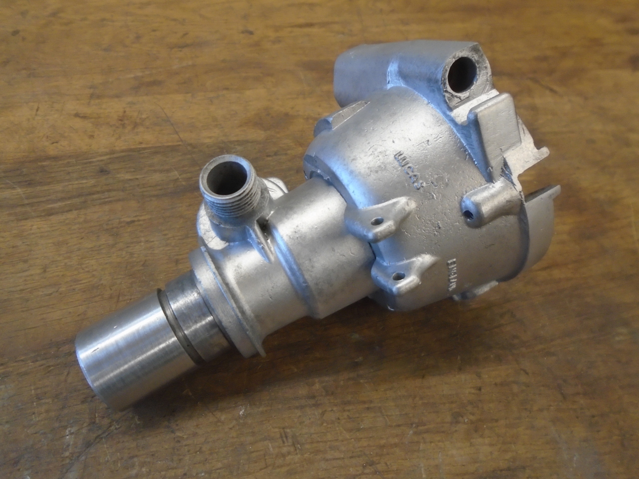
This pot metal won't keep that finish, though, and it will
gradually morph to the faded, mottled finish we are used to
seeing on these kinds of parts. For that reason, I've
lately taken to powder coating many pot metal and aluminum
parts.
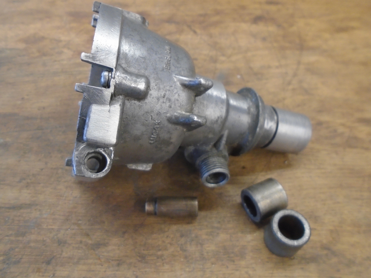
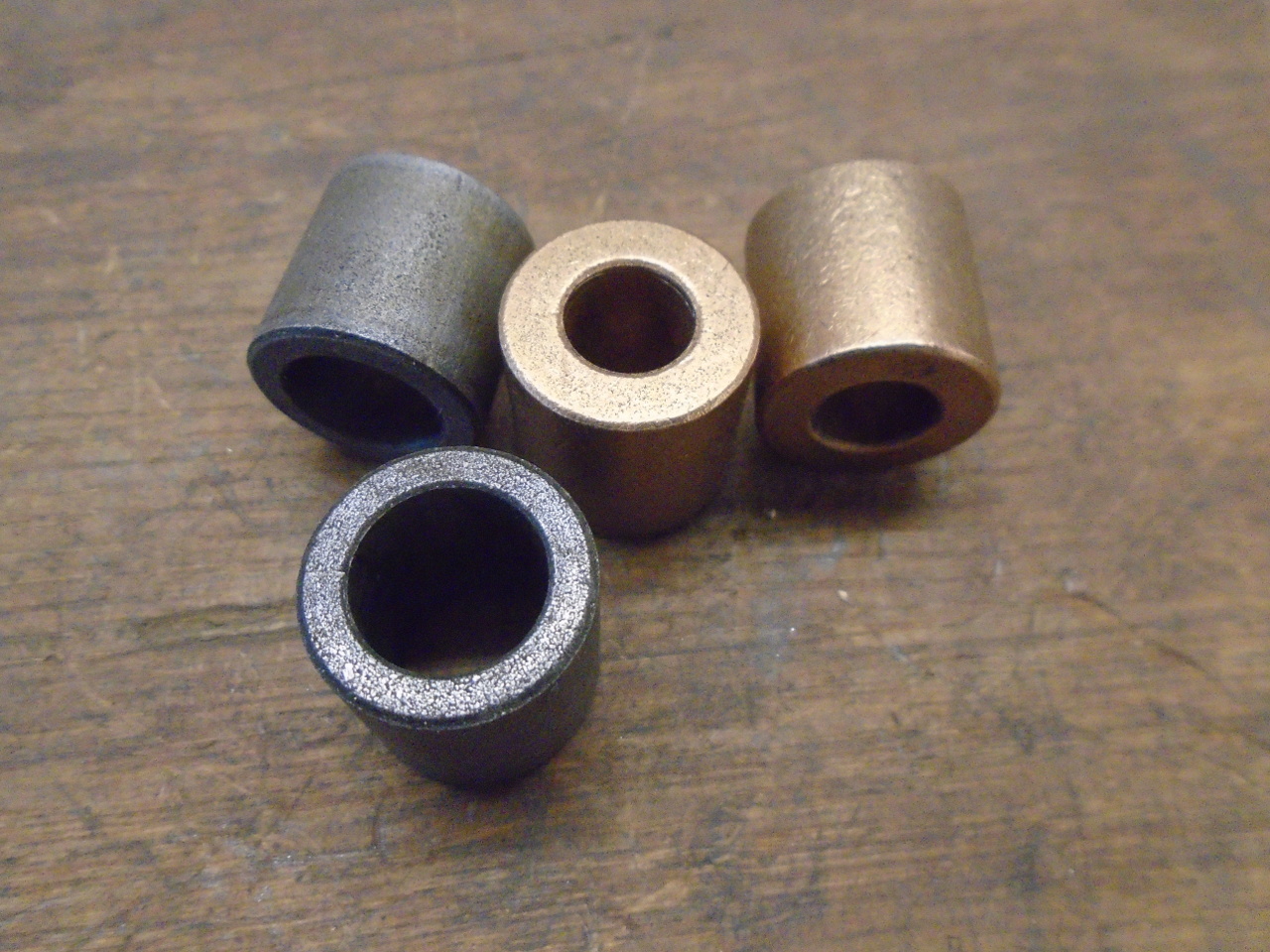
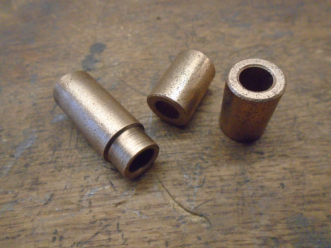
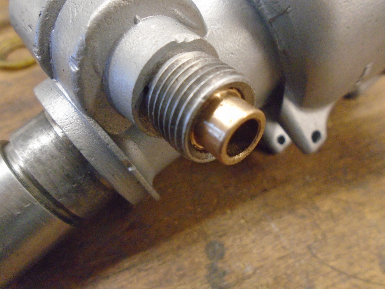
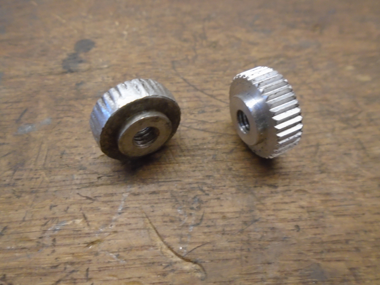
So then we come to the bushings. I discovered when I did
my TR6 distributor--also a 22D unit--that Lucas opted to use a
non-standard size for the spindle bushings. The OD, which
looks like 3/4", is slightly less--about 0.745. The ID,
which looks like 1/2", is also less--about 0.490". I
suppose this was intended to keep dealers from going out of
network for replacement parts.
In the past, I bought these bushes from a popular distributor
repair house specializing in British cars. They were a
little reluctant to sell to me though, and the price reflected
that. This time, I just bought some inexpensive standard
3/4" OD x 3/8" ID bushes and resolved to adapt them
myself. Original bushes on the left are sintered
iron. I chose sintered bronze.
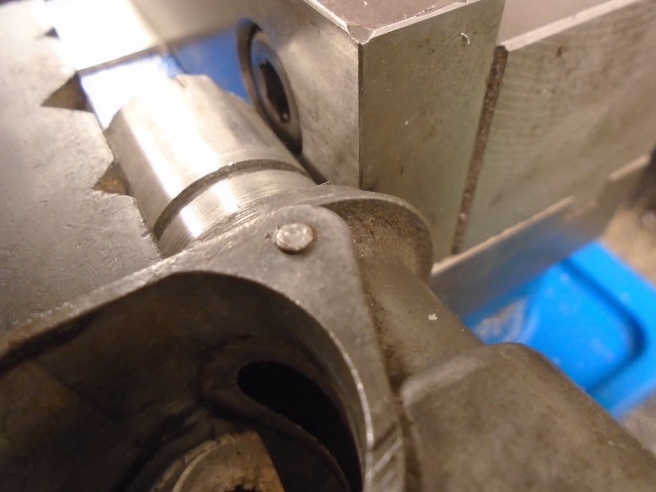
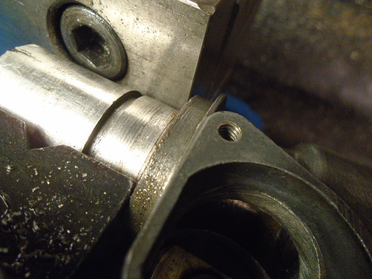
After machining the OD to final size and the ID to just under
final size, the bushes were pressed into the body.
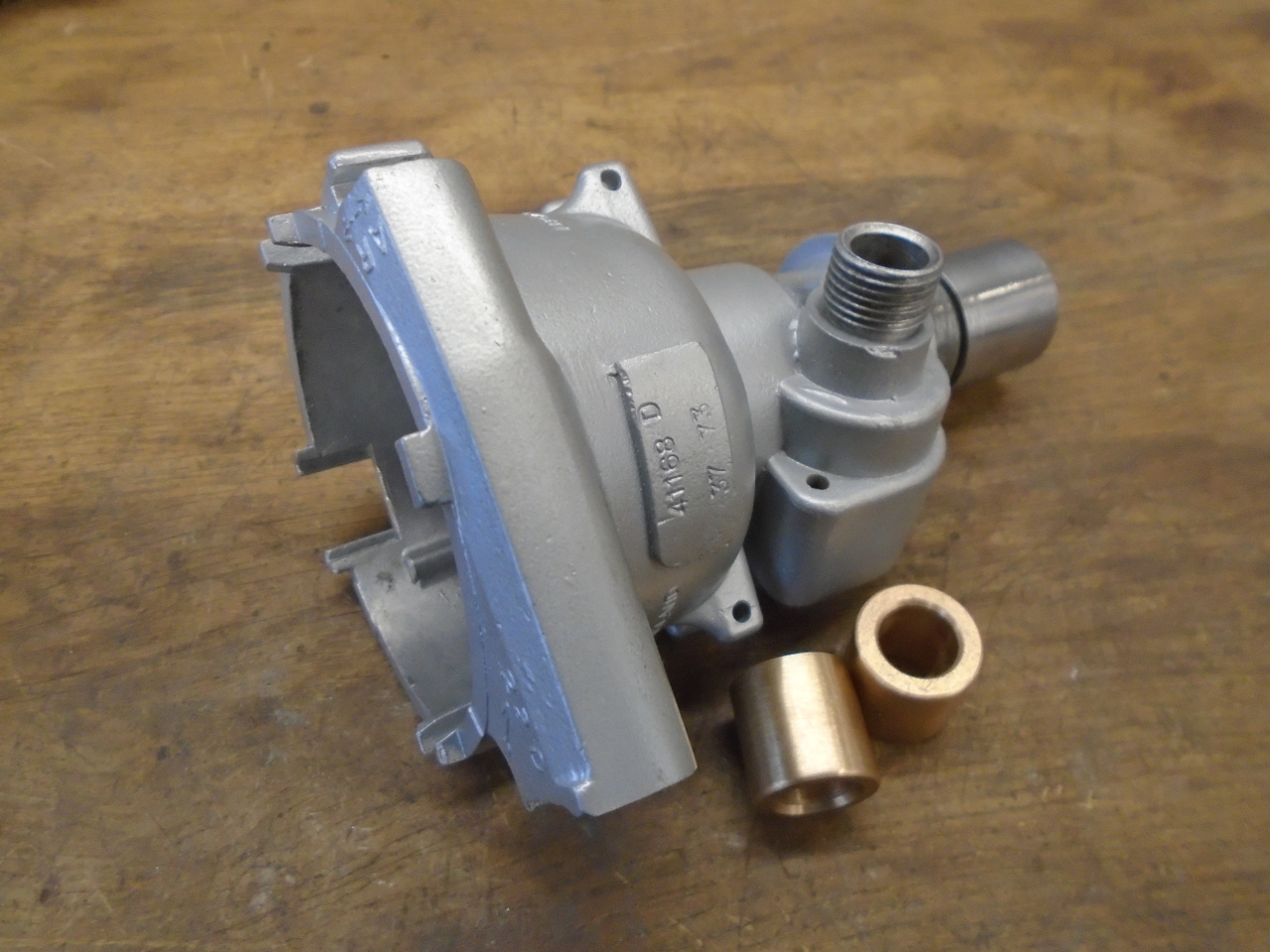
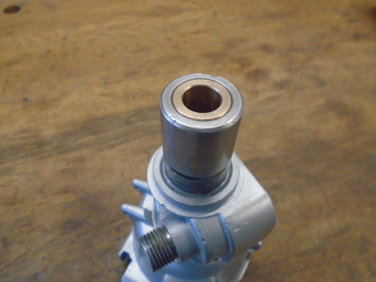
There are a couple of reasons for leaving the IDs a little
small. First, Oilite bushes can compress a little when
pressed into place. Second, in a situation like this,
where you want a pair of bushes to have a very nice fit to a
shaft, they really need to be reamed to size. Further,
it's best to "line-ream" them in situ, to ensure that the bores
are coaxial.
Machining these "Oilite" type bushes can be a little
tricky. The sintered material retains oil in pores, and
machining can smear the material, closing up some of the
pores. Very sharp tools minimize this. My spindle
measured 0.489", so I reamed the bushes to 0.491". The
result was a very nice fit, firm but smooth, with no detectable
play.
The tach drive bush was simple by comparison. It's a
standard size--7/16" OD x 1/4" ID. I couldn't find the
right length, though, so I went with a pair of shorter
bushes. The step had to be machined.

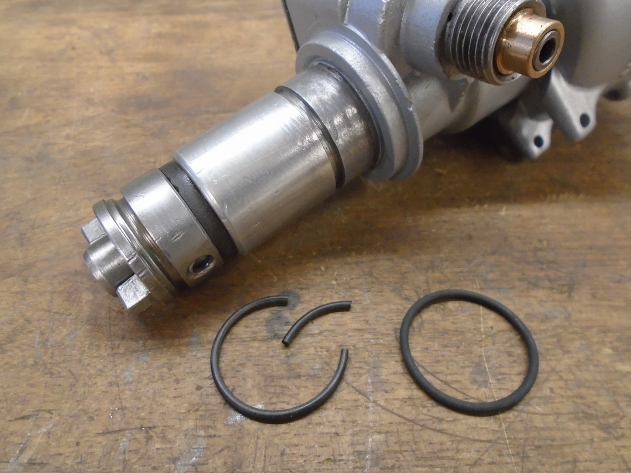
Assembled the tach drive bits, with a re-plated cap and home
made gasket, since I can never remember to order gaskets.
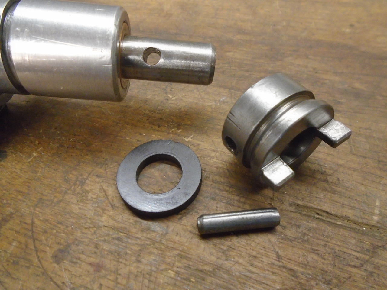
Then the drive dog, and a new O ring. The old ring was
cooked hard. The new one is Viton, which should take the
heat better.
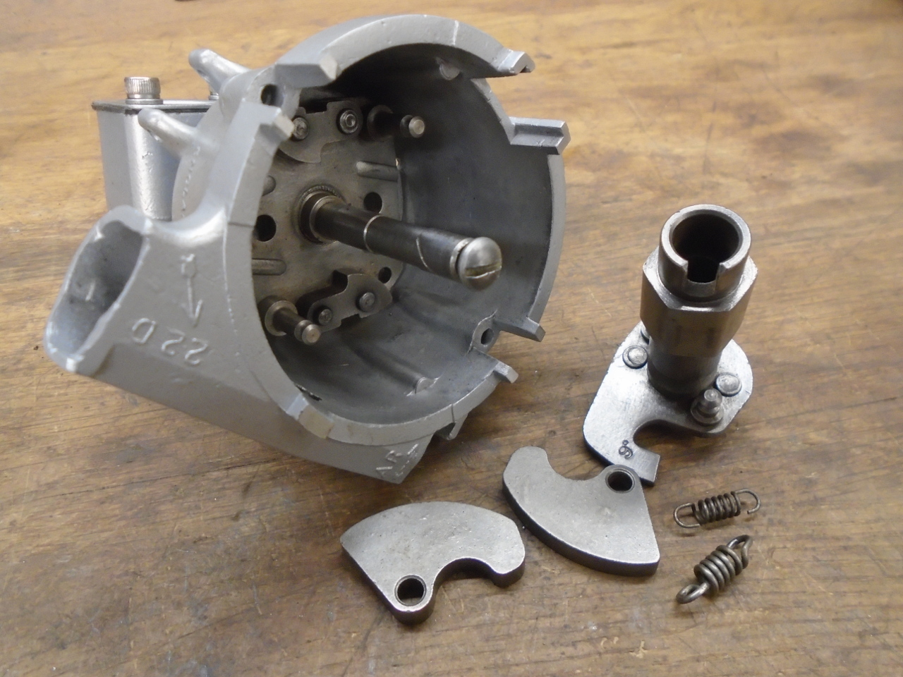
Then it was time to assemble the top end. I'm sure I
replaced the springs during the last refresh, so they are old,
but don't have many miles on them.
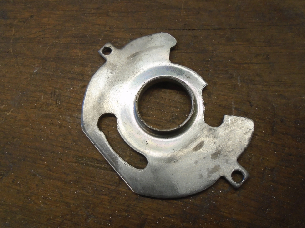
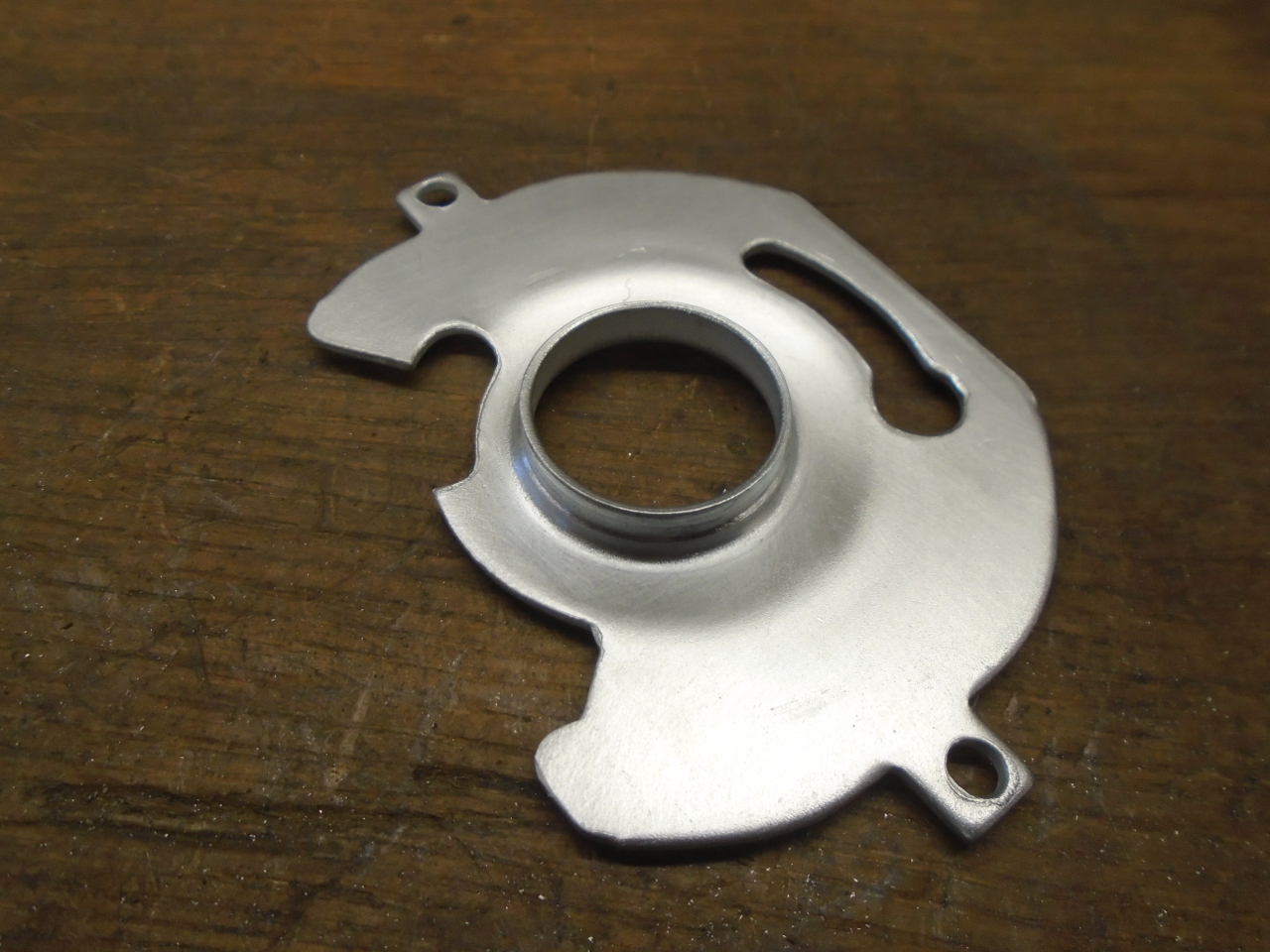
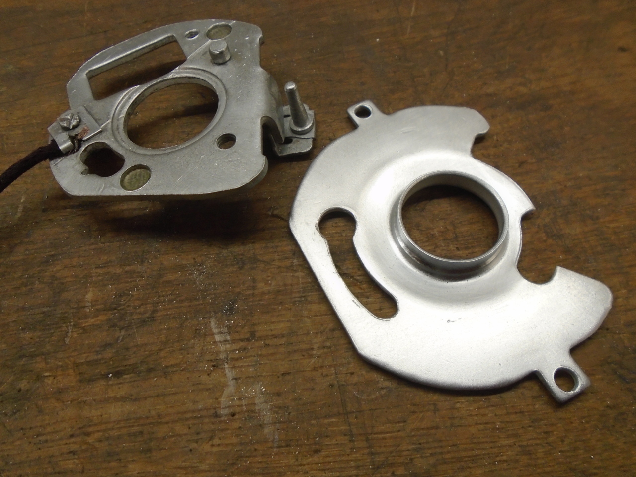
The main backing plate looked a little tired, but some new zinc
made it look new. The rotating plate above it was also
tired, but it has a lot of attachments on it, so I didn't want
to acid strip it. I just put a fresh flash coat of zinc on
top. It doesn't come out as shiny that way.
Next was the vacuum advance unit. It was dirty and rusty,
but cleaned up OK. I had no idea if it was still working
after nearly 50 years.
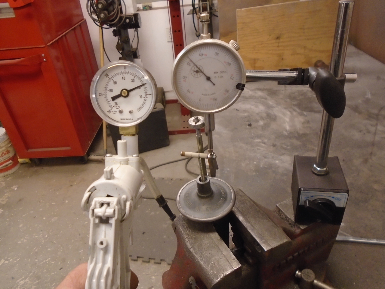
I was curious about that, so before just tossing it, I decided
to test it. I put together a simple test setup with a hand
vacuum pump and a dial indicator to show how much the actuator
moved.
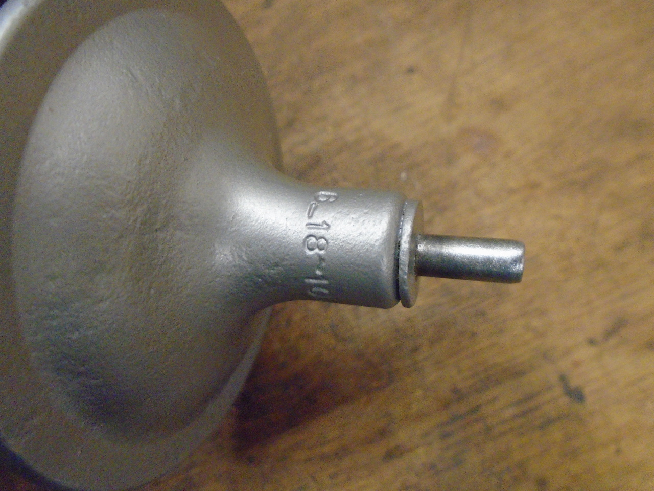
Here is the result. The advance unit is marked
"6-18-10". This means that the actuator starts to move at
6 inches of mercury, and at 18 inches, provides an advance of 10
degrees. The blue line shows the "advertised" advance
curve. The red line shows what I measured. Actually,
I just measured displacement of the actuator of the unit. I had
to calculate what advance would result from the movement.
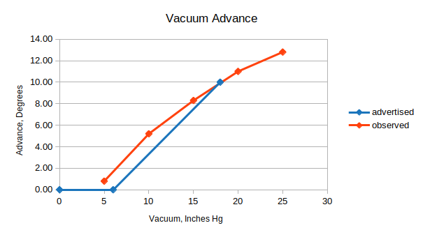
I think the approximation
is pretty good, actually. No one really believes that the
code marking on these units are dead on accurate. I'm
going to go with this vacuum unit until I have reason to think
it isn't working.
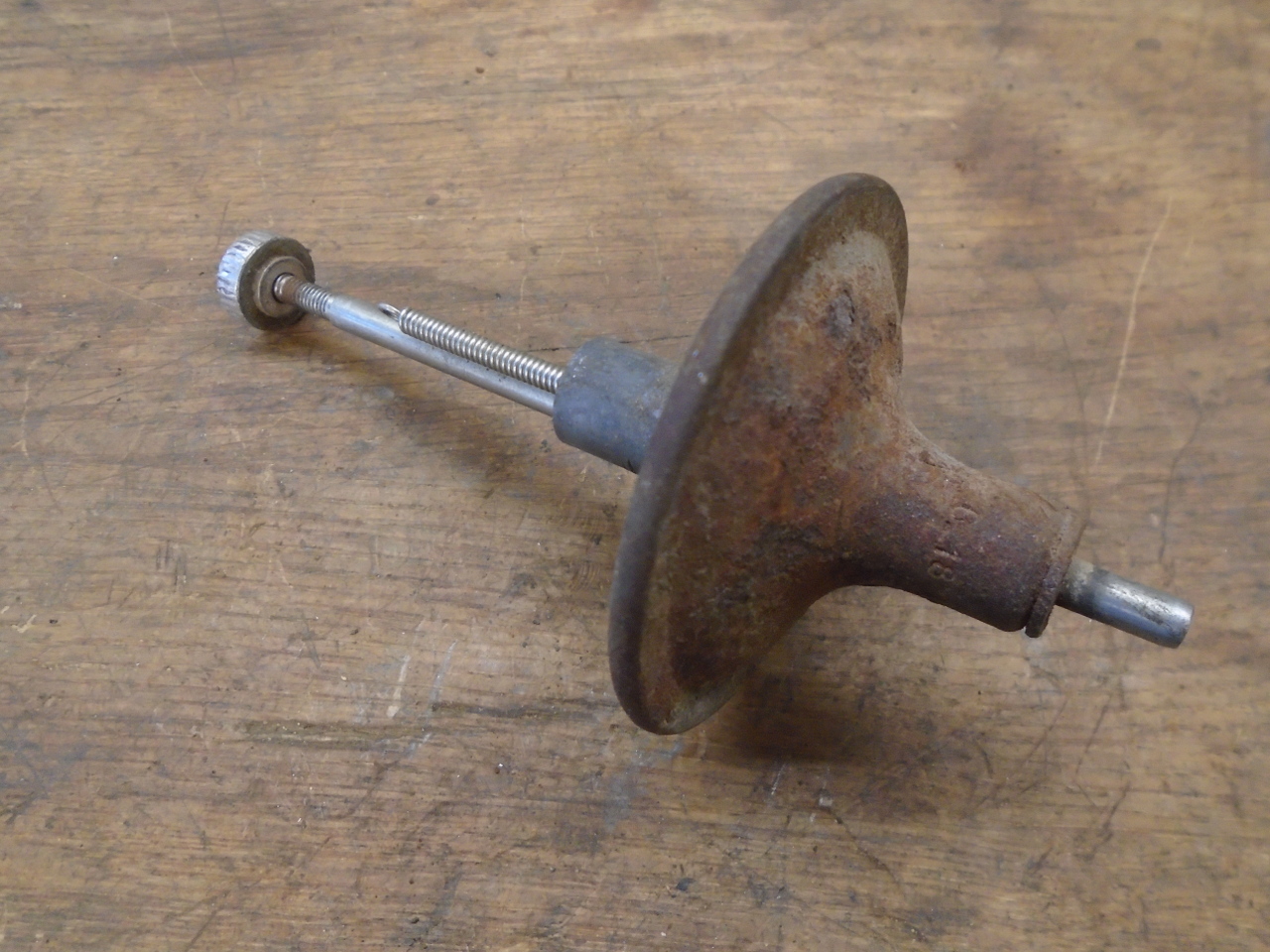
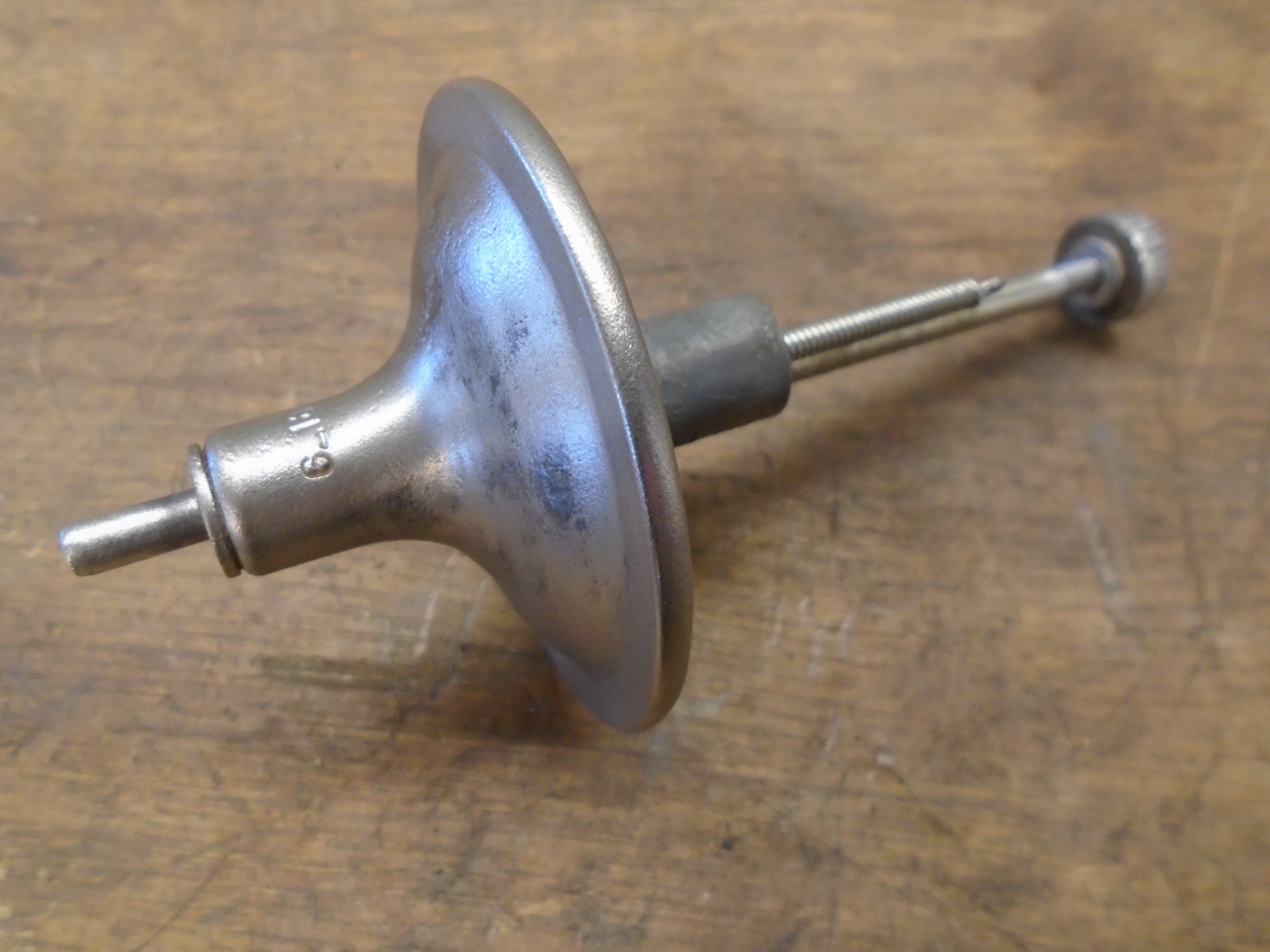
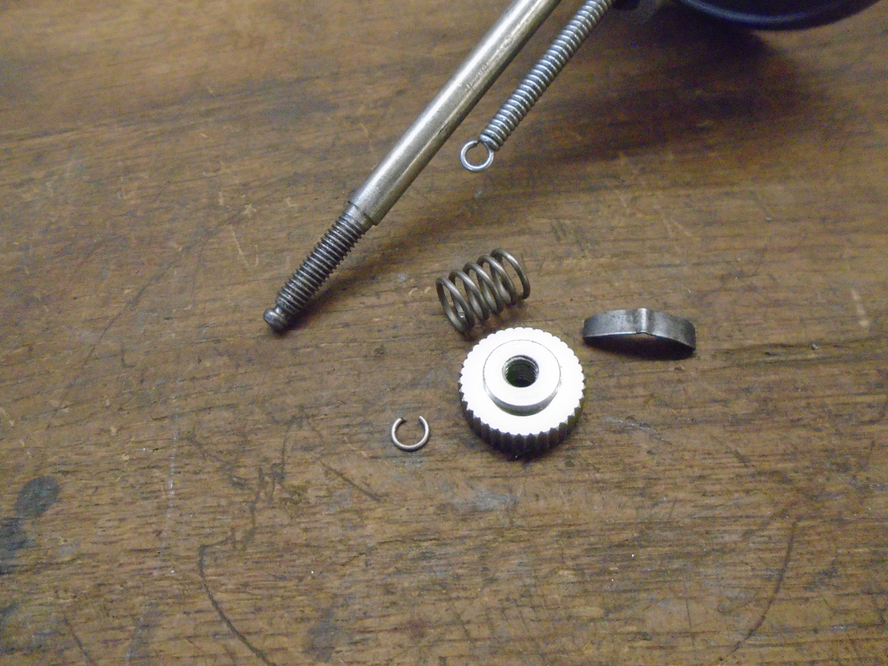
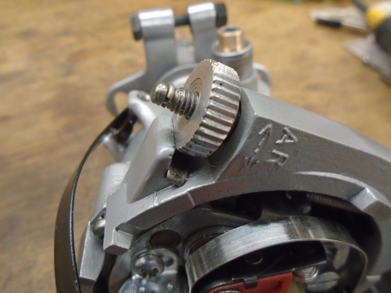
There was one little annoyance with the vacuum unit,
though. The timing micrometer adjuster wheel was really
worn. Its detents were all but gone. I guess you can
buy these, but I really wanted to wrap this project up, so I
devoted a couple of enjoyable hours to making one. It was
complicated by the fact that the thread is not imperial, not
metric, but the odd British 2BA.
The other parts of the micro adjuster. The spring was
missing, as was the little keeper for the end of the threaded
rod. A root through my "box o' springs" turned up a
suitable spring. The keeper was simply a coil snipped from
a smaller spring.
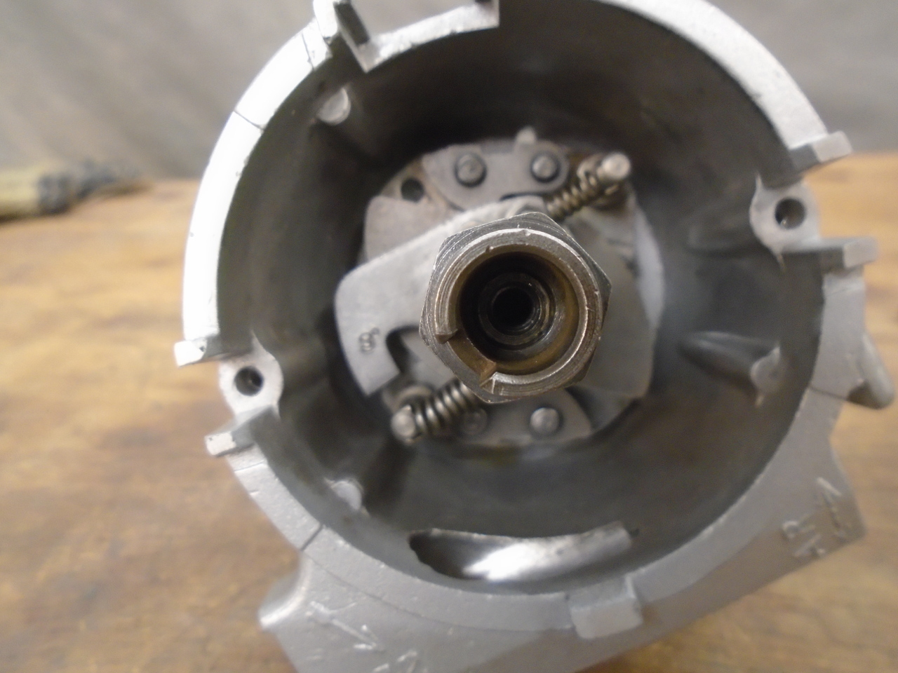
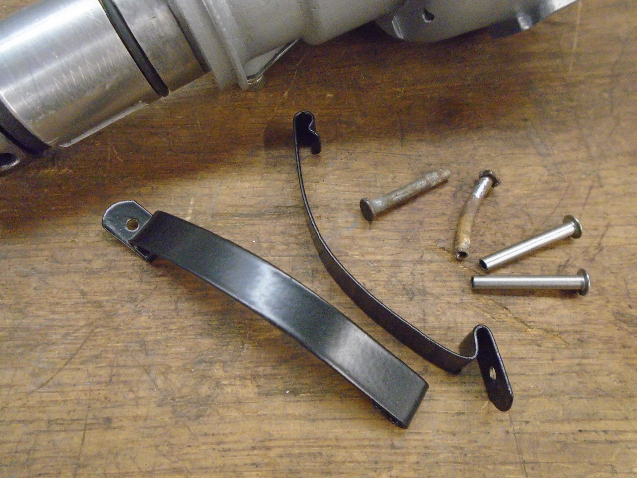
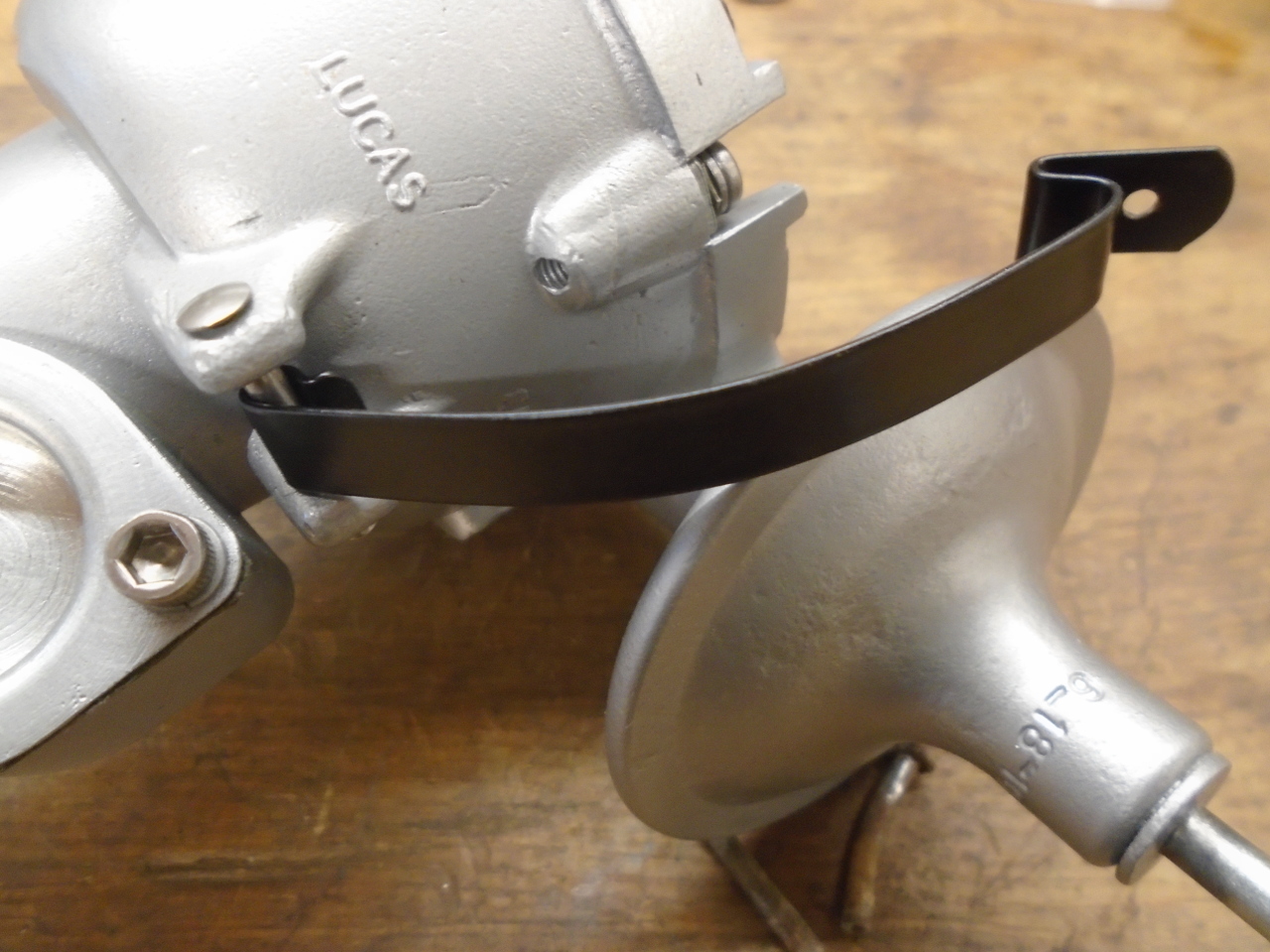
Powder coated the spring retainer arms and put them back in
place.
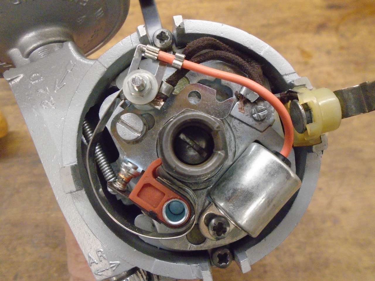
Installed new points, condenser, rotor, and cap. On the
shelf with this dude.
A few good challenges on this one. That keeps it interesting.
Cost was just for the tune-up kit, what ever that was, plus
something under $10 for the bushes.
Comments to Ed at: mailto:elhollin1@yahoo.com
To my other GT6
pages