To my other GT6
pages.
January 21, 2020
Intake Manifold
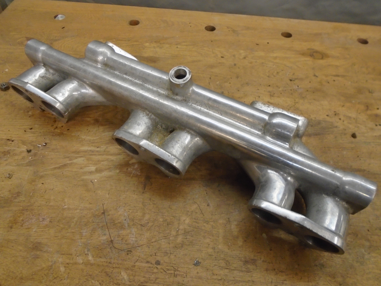
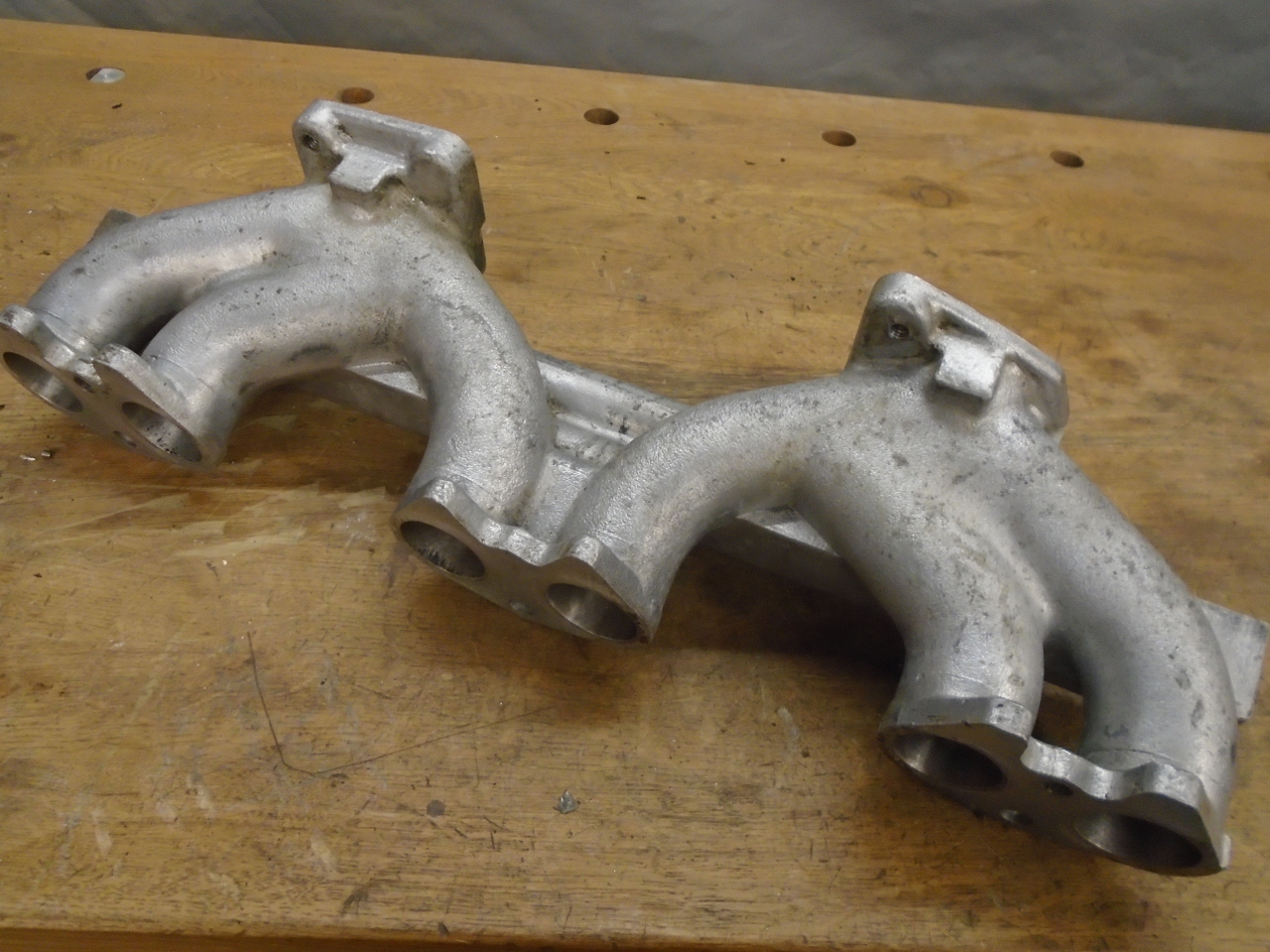
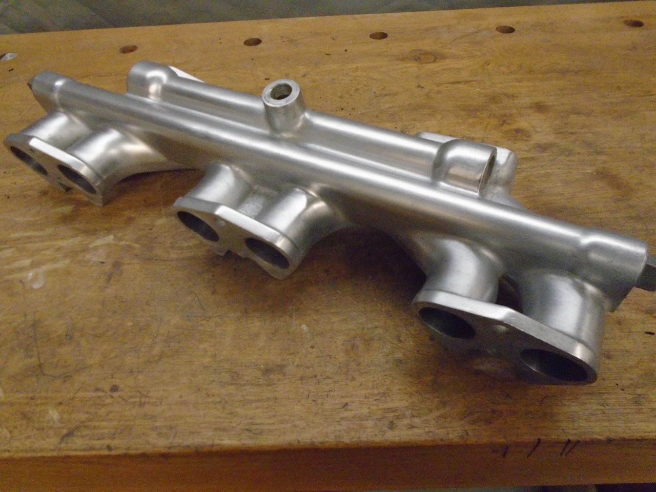
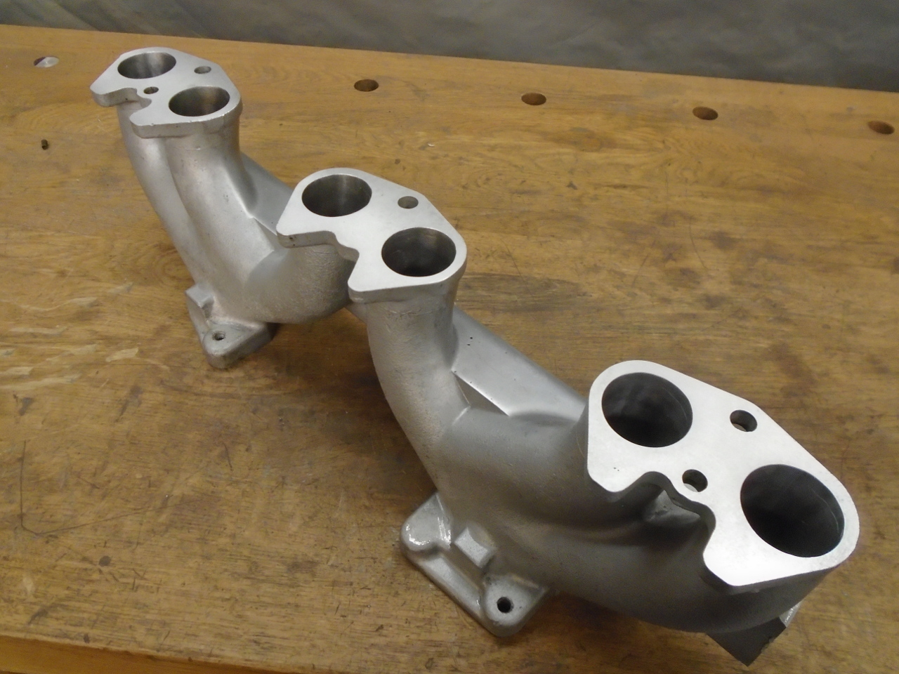
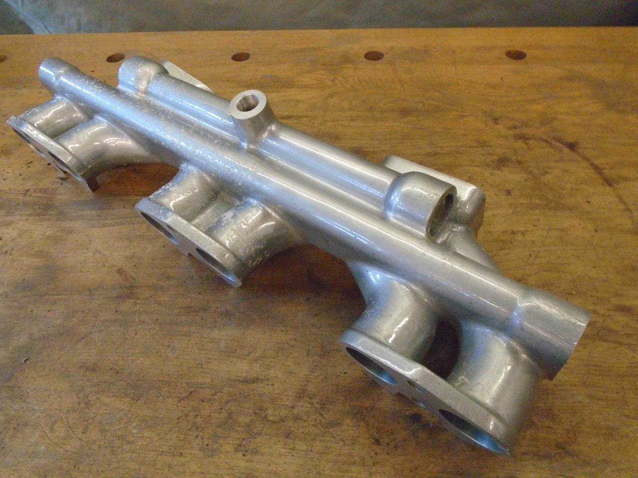
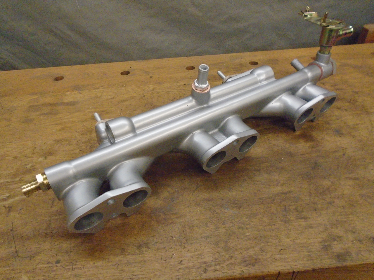
The intake manifold on the GT6 is an aluminum
casting that provides passages from each carburetor to three
adjacent intake ports on the cylinder head. In this sense,
the engine is a little like two coupled three-cylinder engines,
each with its own carb. It appears that the designer
attempted to provide approximately equal length runners for each
port, though this meant that the center runner of each bank
(cylinders two and five) has a pretty significant jog in its
path. The manifold also includes an integral balance tube
between the carb mounting throats, and a passage for coolant,
presumably to improve warmup, and to keep the manifold at a
relatively constant temperature during operation.
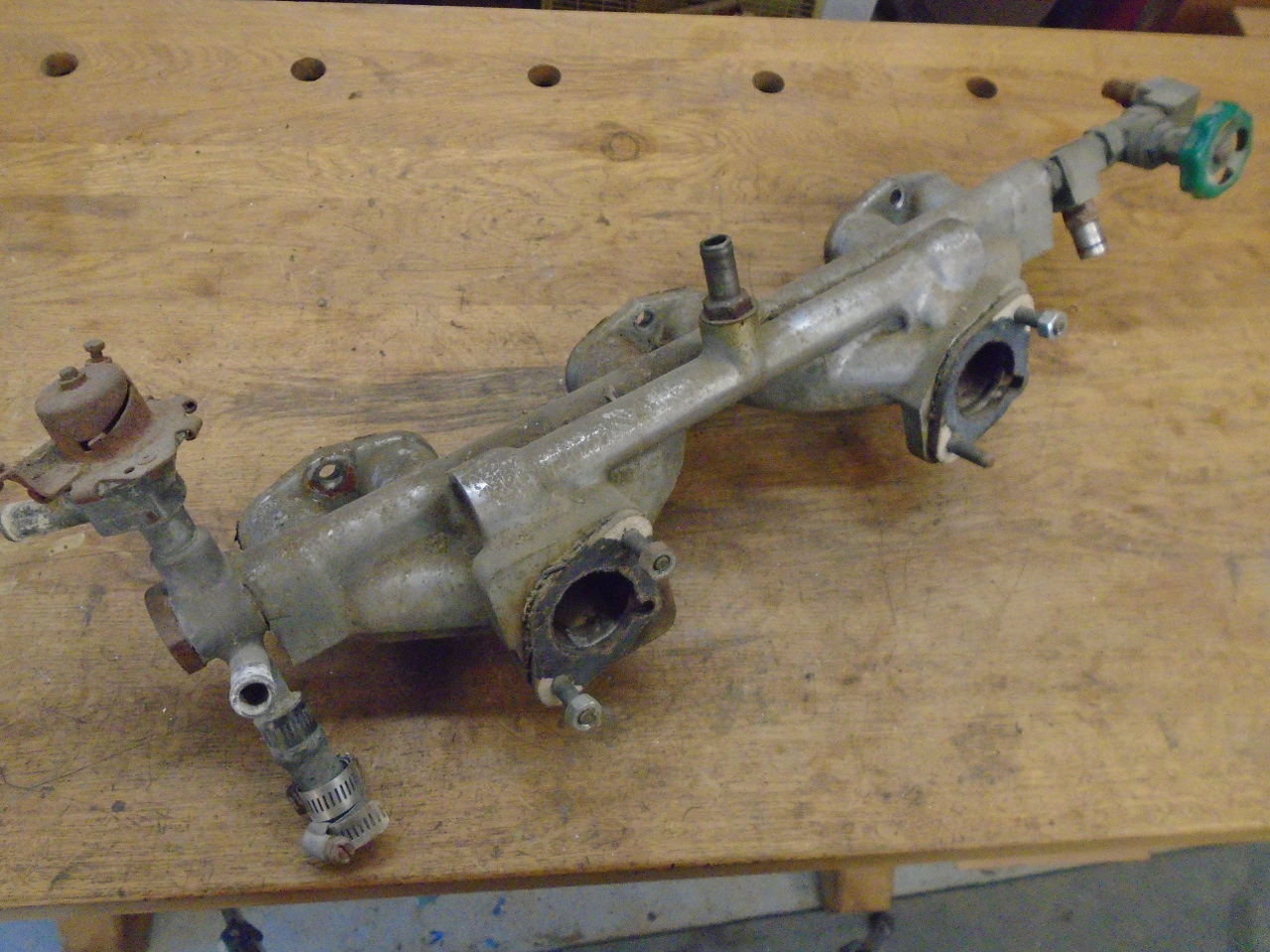
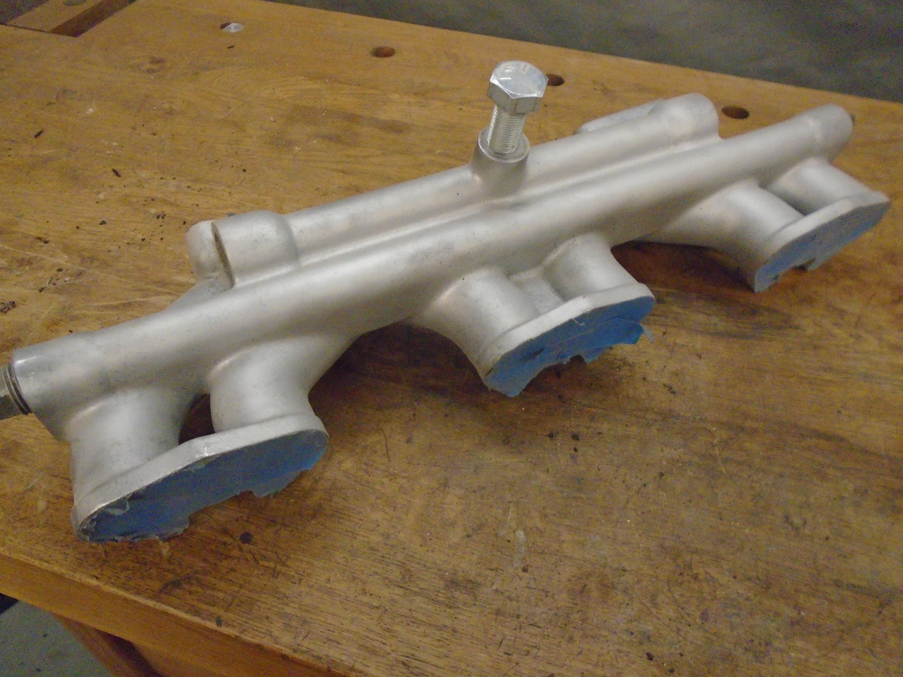
My manifold was grimy, but appeared to be intact. I think
the non-standard fittings at the far end were my early attempt
to mitigate the effects of the stuck-open heater valve.
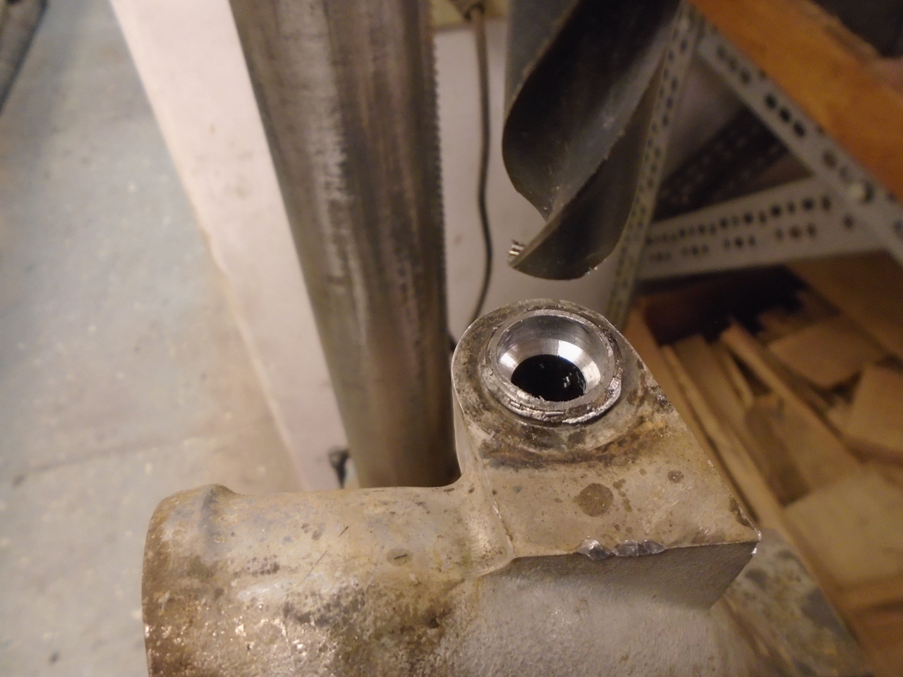
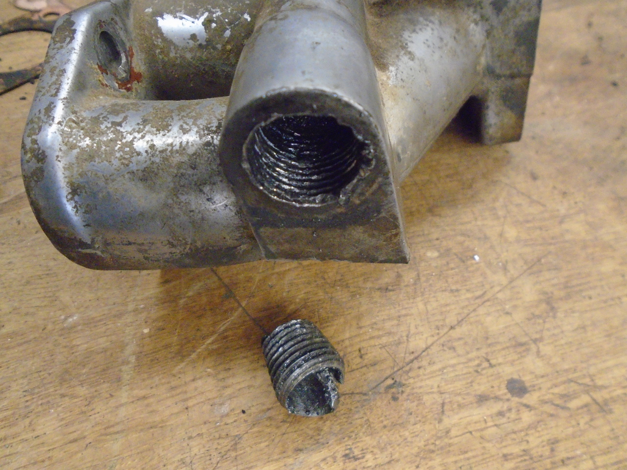
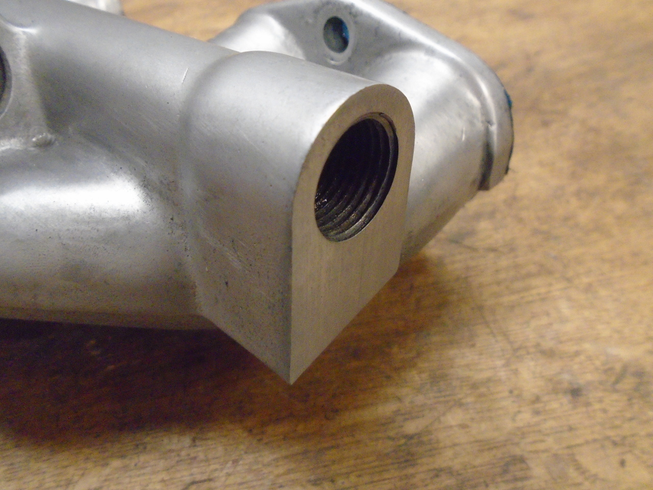
Removing the various attachments to the manifold casting
produced some heartache. First, the heater valve left most
of its threads behind when removed. Then the banjo bolt
was being troublesome. When I had to resort to an impact
driver, the bolt decided to sacrifice itself rather than come
out peacefully.
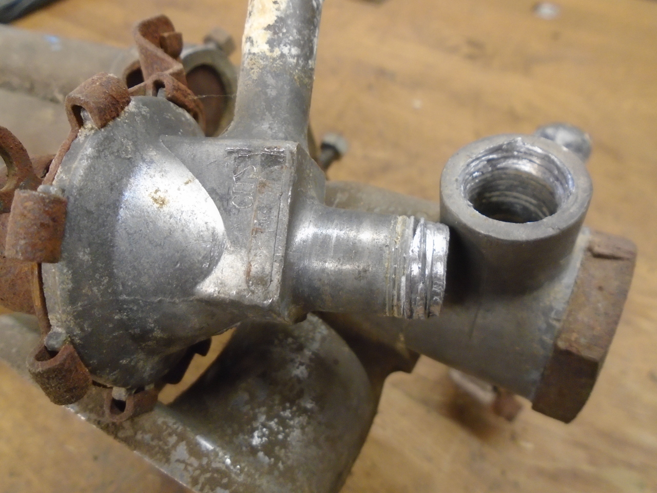
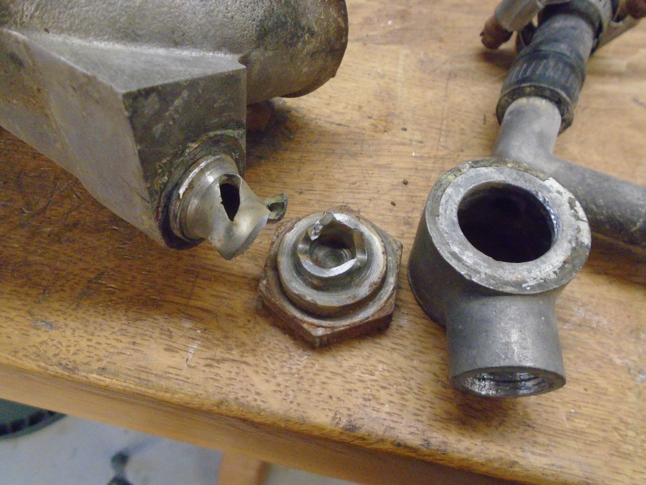
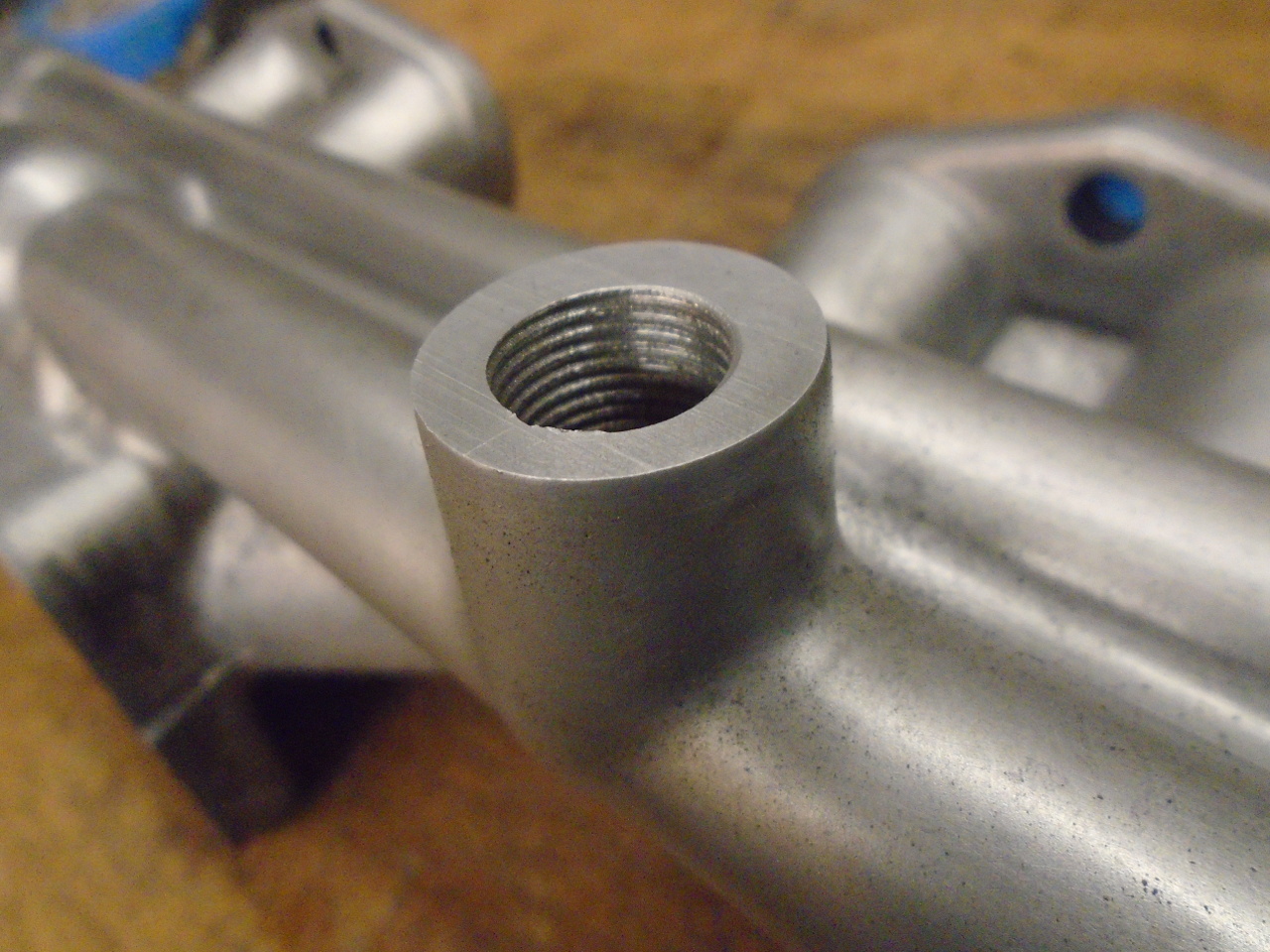
Removing the remnants of the banjo bolt was a couple of hours
detour. The threads in the manifold were a little damaged,
but running a tap into them improved them a lot.
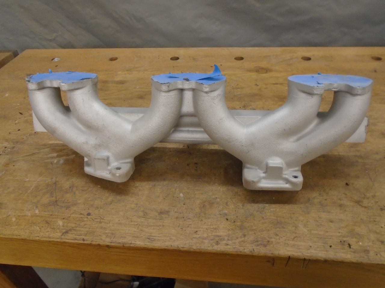
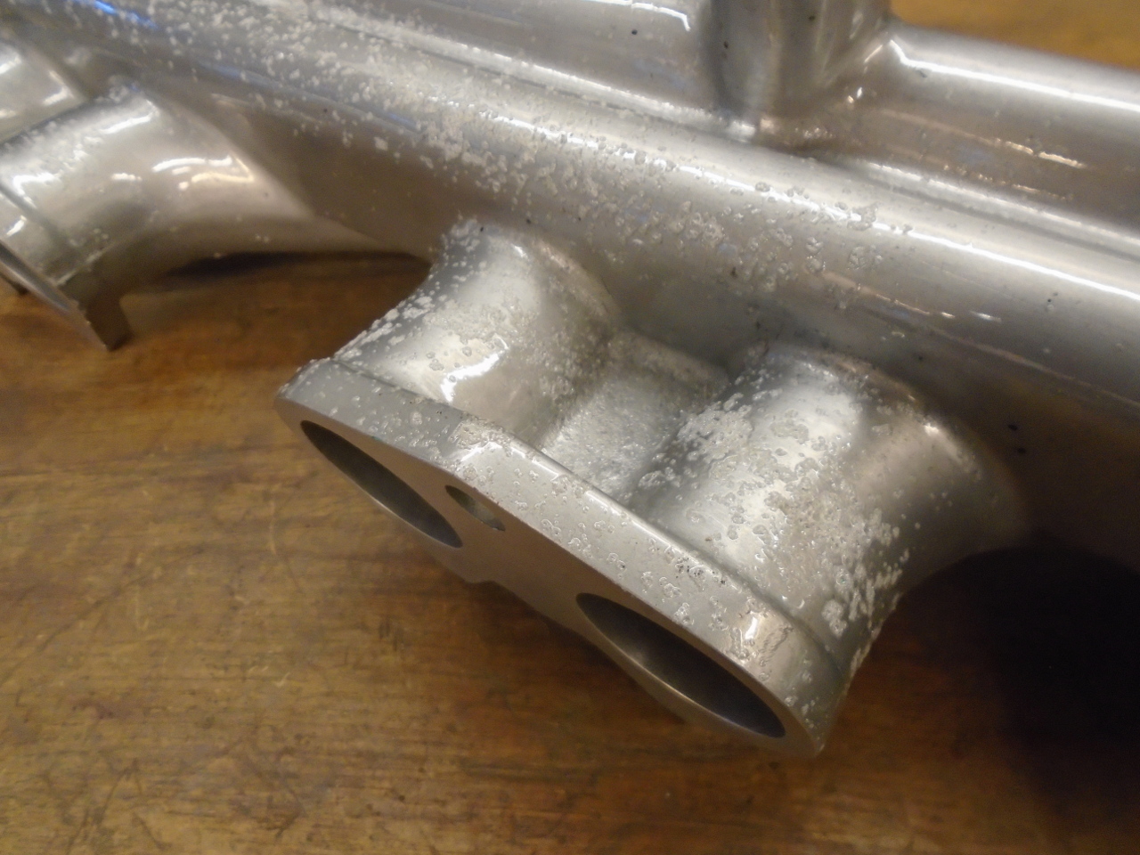
There wasn't really a lot to do inside the manifold. I had
already matched the head-side openings to the head gasket
decades ago. Likewise with the carb side openings.
Other than that, there was just a little shaping of some ridges
on the carb side where the machined throats meet the cast
cores. It wasn't much--maybe only 1/16" or so is all it
took to make a smooth transition.
After cleaning up the casting with soap and water, I remembered
that I had polished up the topside back in the 80s. It
still looked sort of OK, but there was a lot of stains and
mottling on the shiny surface.
To try to even out the surface finish, I popped the manifold
into the blast cabinet and gave it a light once-over. The
result was a more even, but matte, finish.
A little wire brushing and some Scotchbrite brought back the
shine.
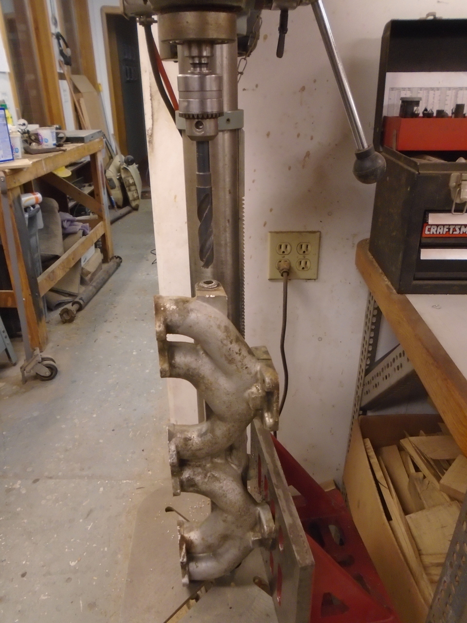
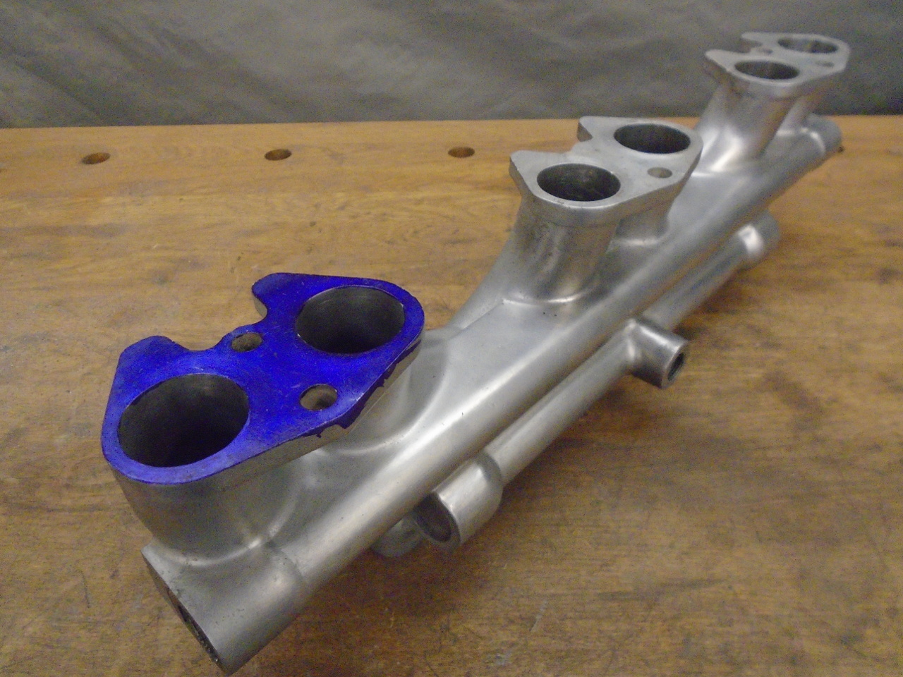
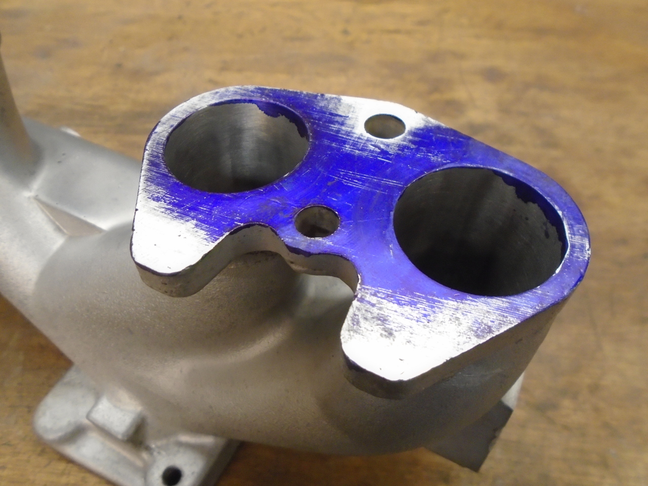
Before I went any further with the surface finish, I wanted to
check out the mating surfaces. This is blue layout
compound on one of the head side mounting flanges. Giving
the flange a few rubs on a flat plate with fine sandpaper glued
to it easily shows the high spots. Not surprisingly, it
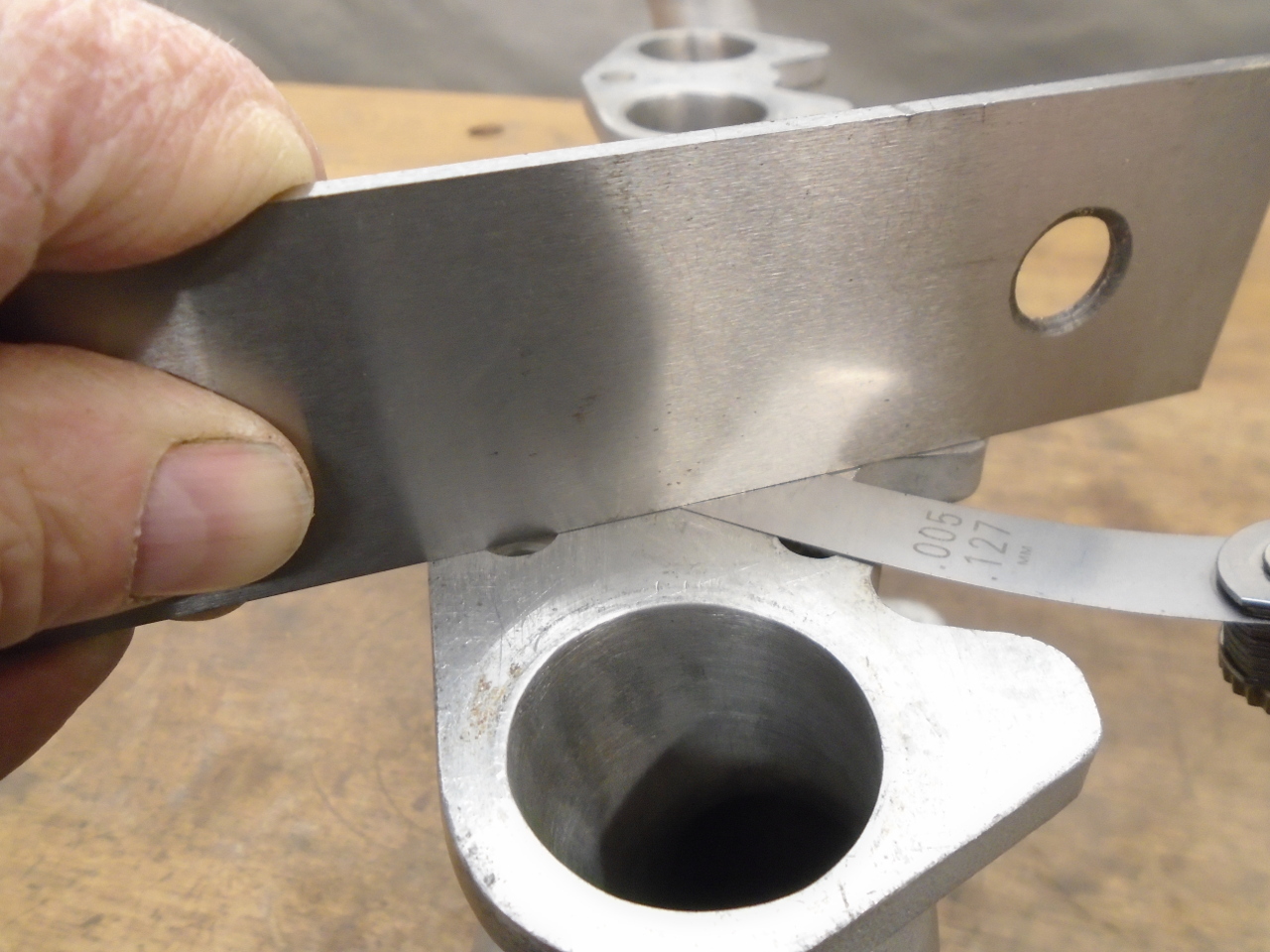
was high where it was clamped. Once I knew the pattern, I
could check the other flanges with a straightedge and feeler
gauges. The un-flatness was a little under 0.005" on all
of the flanges. That's not huge, and may not even
represent a problem, but on the other hand, it's pretty easy to
fix.
Skimming 0.005 cleaned up the flanges nicely. They are now
all flat and co-planar.
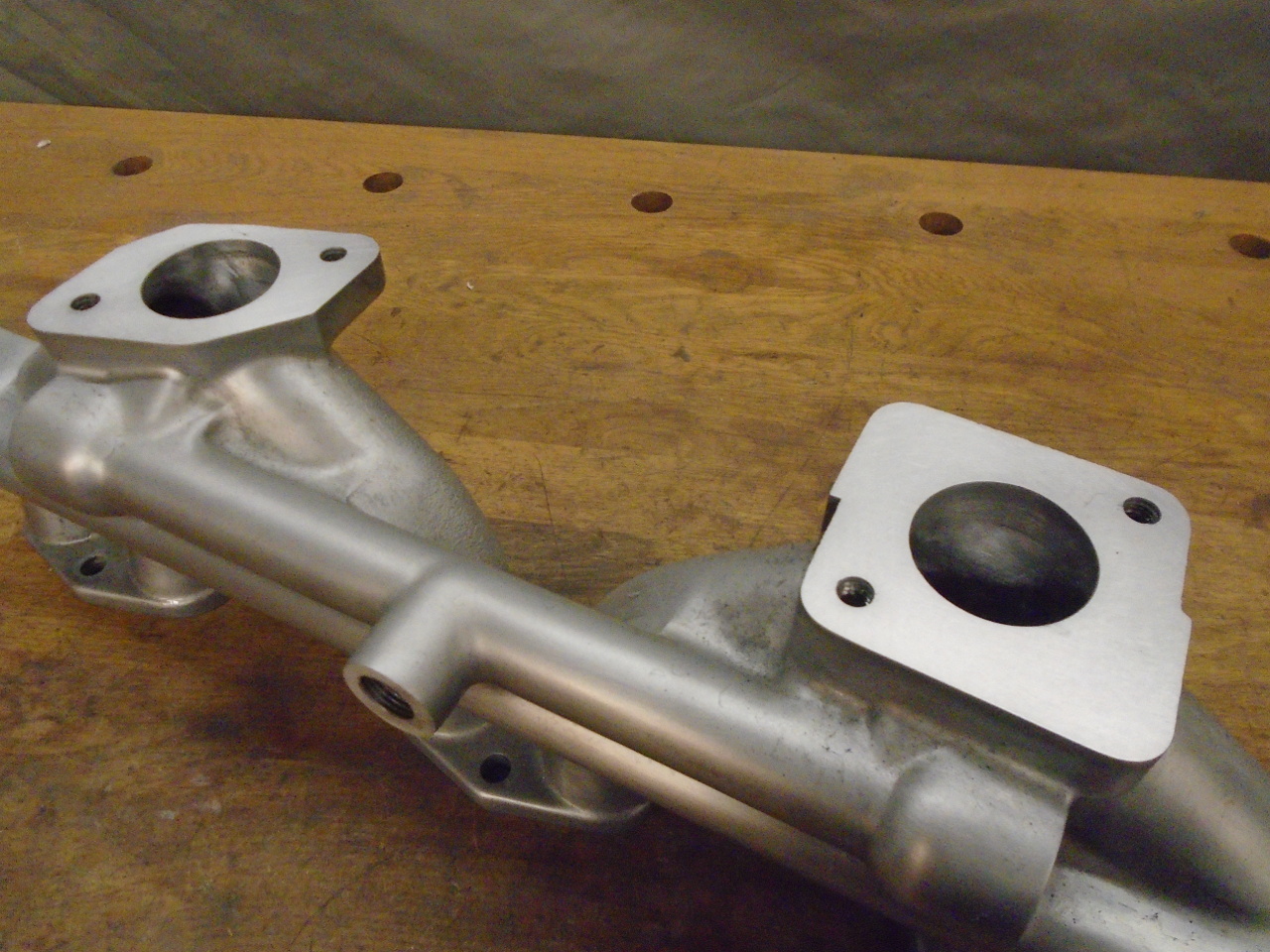
I did the the smaller sealing surfaces, too. They took
quite a bit more to clean up--almost 0.020".
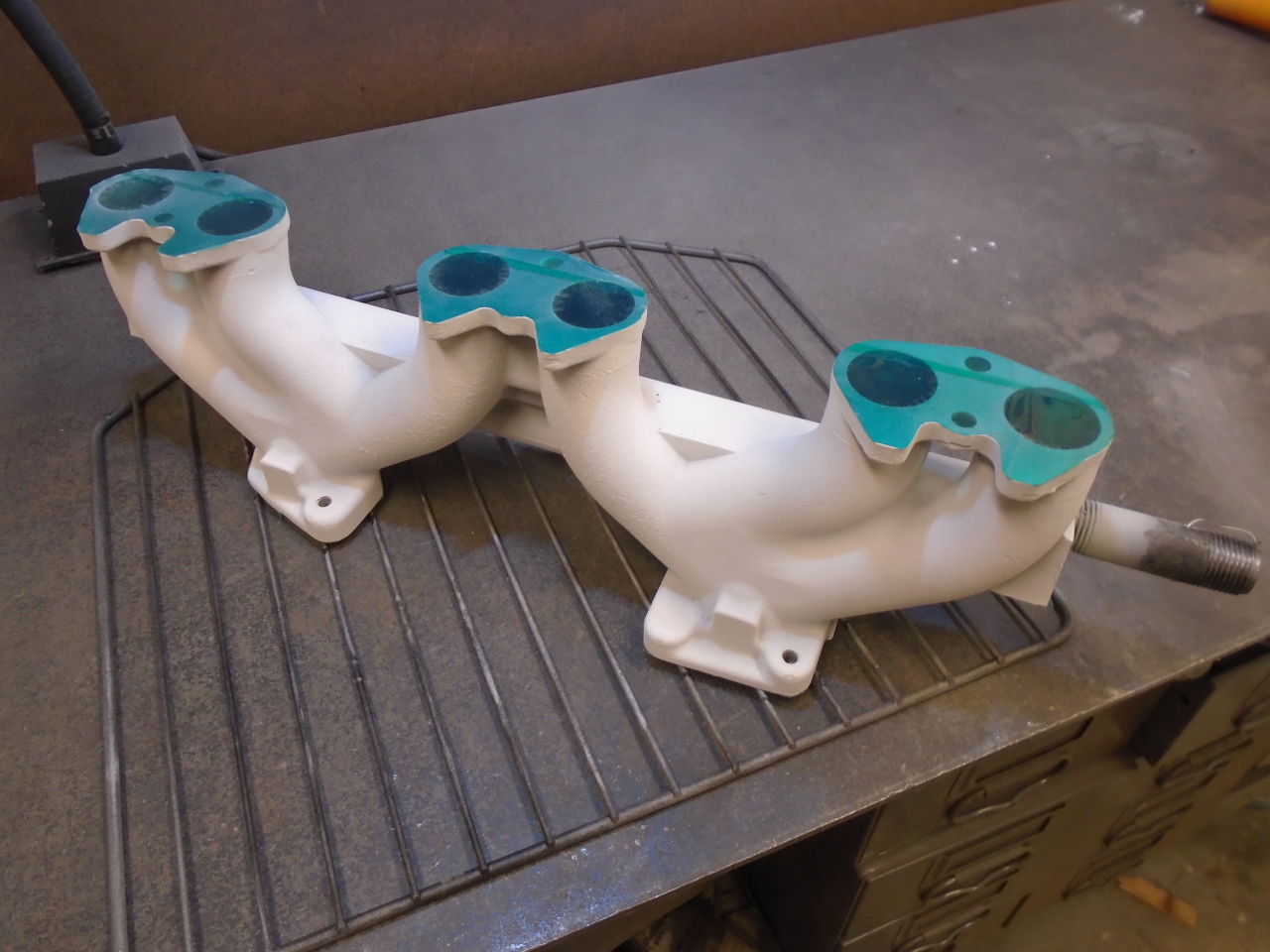
Then I had to decide what to do about the surface finish.
The manifold looked OK from a few feet away, but up close, it
was easy to see some imperfections--mostly porosity. Also,
I knew that even though the aluminum will take a pretty good
polish, it won't last long in the hostile environment of an
engine bay. I decided to try a clear powder coat to
preserve the shine. Clear powder coat goes on white.
It was a tight fit in my small oven.

Well, the clear powder coat was a big fail in several
ways. First, I decided I didn't really care for the high
gloss finish. Second, there was a lot of bubbling on some
areas. I blame this on a combination of the porosity and
my cleaning regimen. Before applying the powder, I washed
the part in detergent and water. Even though I dried it
well, I think there was still water in some of the pits.
The water boiled off in the oven, causing the bubbles in the
melted powder.
An additional reason for abandoning the idea of powder coating
the manifold was that I began to doubt that the coating could
withstand the temperatures near the head and exhaust manifold.
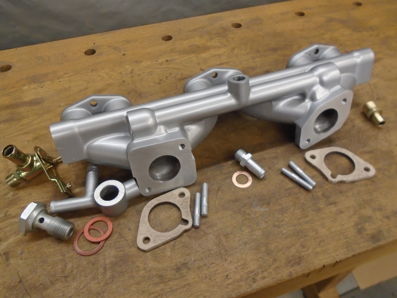
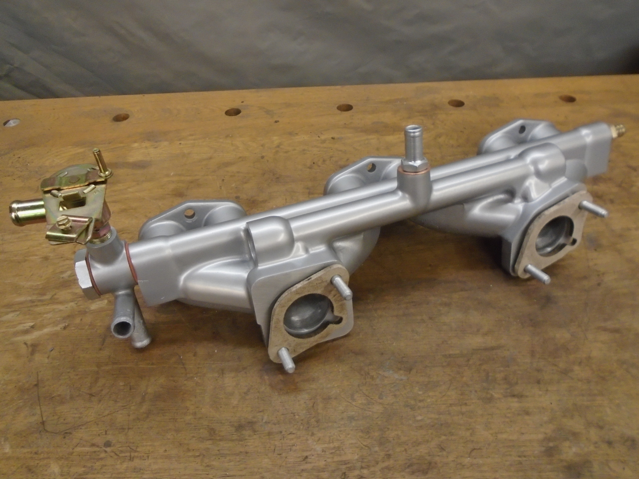
In the end, I decided to just paint the manifold with a good
high temp engine paint. This is all of the parts
associated with the manifold, including the replated original
studs and hose barb fitting. The heater valve is a popular
replacement that uses a much more reliable internal design.
On the shelf with this dude.
I really wish I could have achieved the look I wanted on the
manifold without resorting to paint. But, in the larger
scheme, it's a pretty small issue.
Cost was around $30 for the heater valve.
Comments to Ed at mailto:elhollin1@yahoo.com
To my other GT6
pages.