To my other GT6
pages.
January 12, 2020
Carburetors
[All of the pics are clickable]
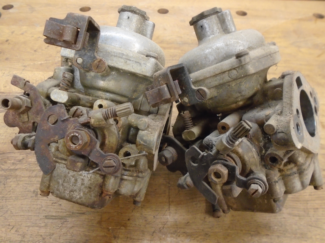
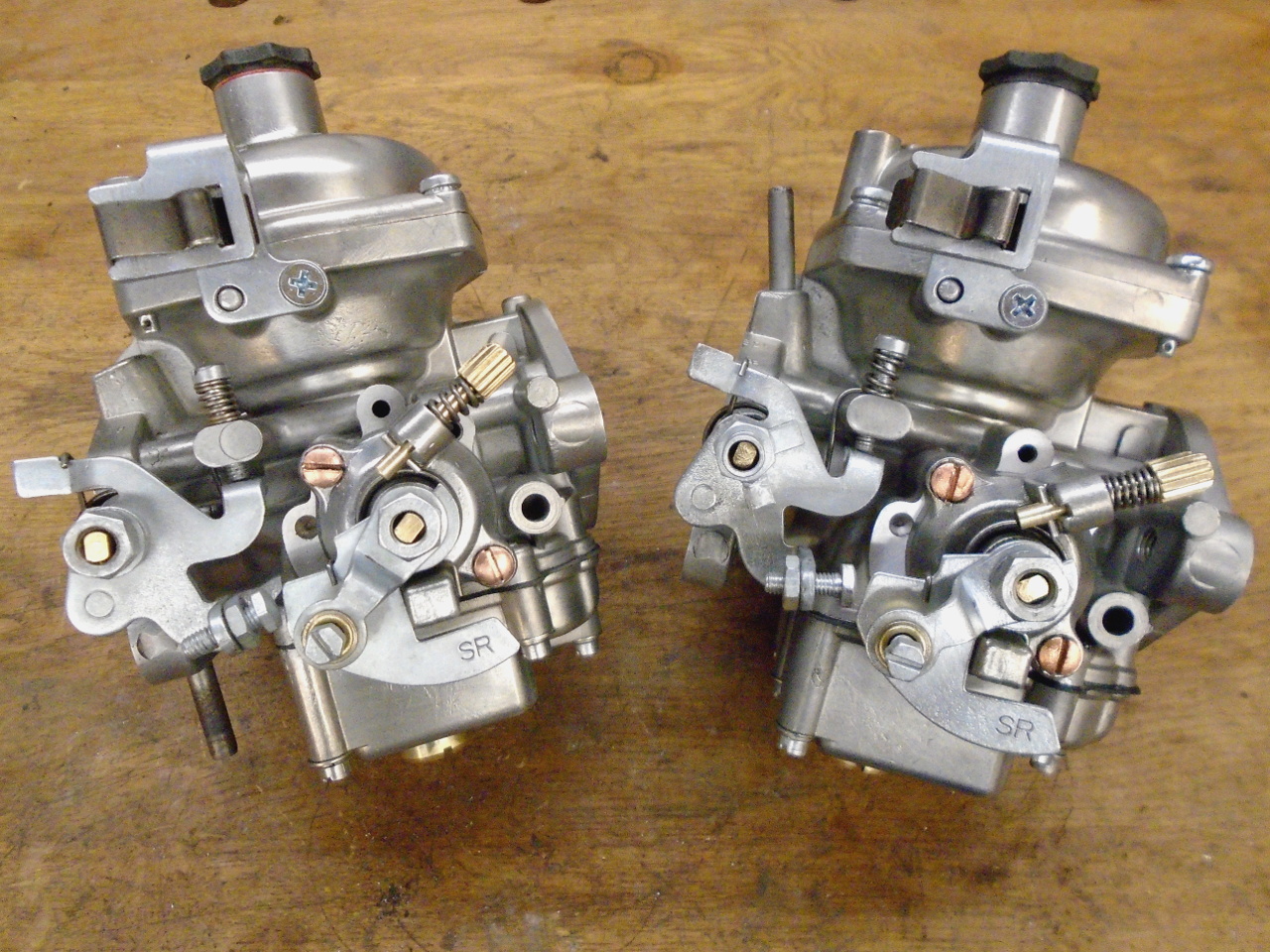
One of the things that adds to whatever mystique these British
sports cars have is their sexy dual side draft
carburetors. Never mind that they have to be synchronized
and can sometimes be finicky, they just look cool. As far
as I know, all GT6 cars came with dual Zenith Stromberg CD150
units. where the 150 refers to the nominal 1.5 inch throttle
bore. The "CD" of the model name refers to Constant
Depression, a carburetor design wherein the area of the venturi
is varied such that the velocity of the air in that area is
relatively constant over the range of throttle openings.
Constant velocity implies a constant depression, or vacuum, to
draw fuel into the air stream.
While older CD carburetors are pretty basic, with only a few
moving parts, the era of clean air emissions controls saw the
simple design encrusted with various add-ons. Though not
marked as such, my carbs were actually 150CDSE units, where the
"E" apparently stands for Emissions. I don't know what the
S stands for.
It is claimed that the emissions gizmos added to the carbs don't
affect engine performance, and I believe that this is
true. However, each one does add complexity, and creates a
new potential failure point, as well as making troubleshooting
more difficult. For this reason, my approach to rebuilding
the carbs is to try return each of these "features" to proper
working condition, and then to defeat them. That way, if I
later decide that the functionality of one of these devices is
needed after all, it will be easy to reverse the defeat.
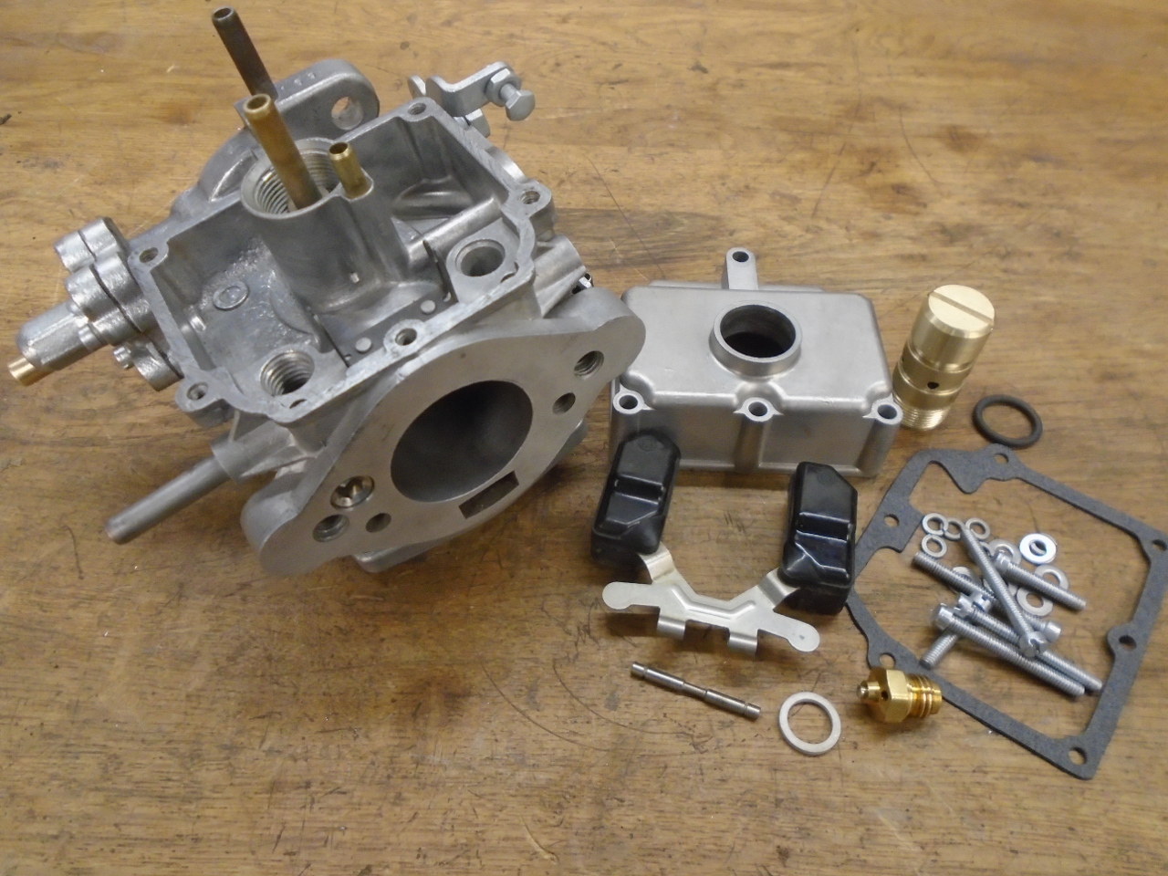
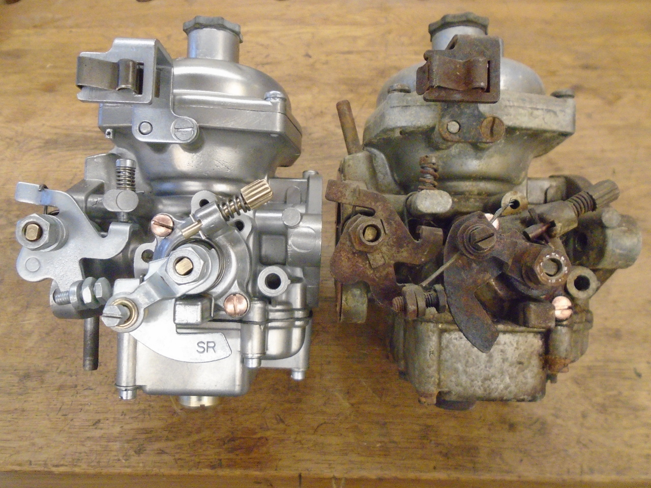
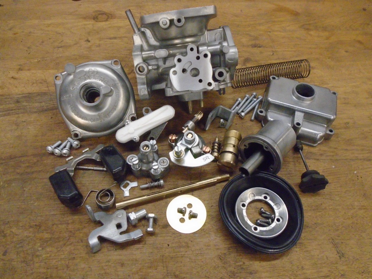
The carbs were appropriately dirty. There are three main
pot metal castings: the main body, the float bowl, and the
top cover.
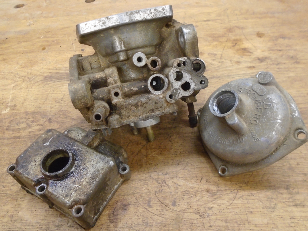
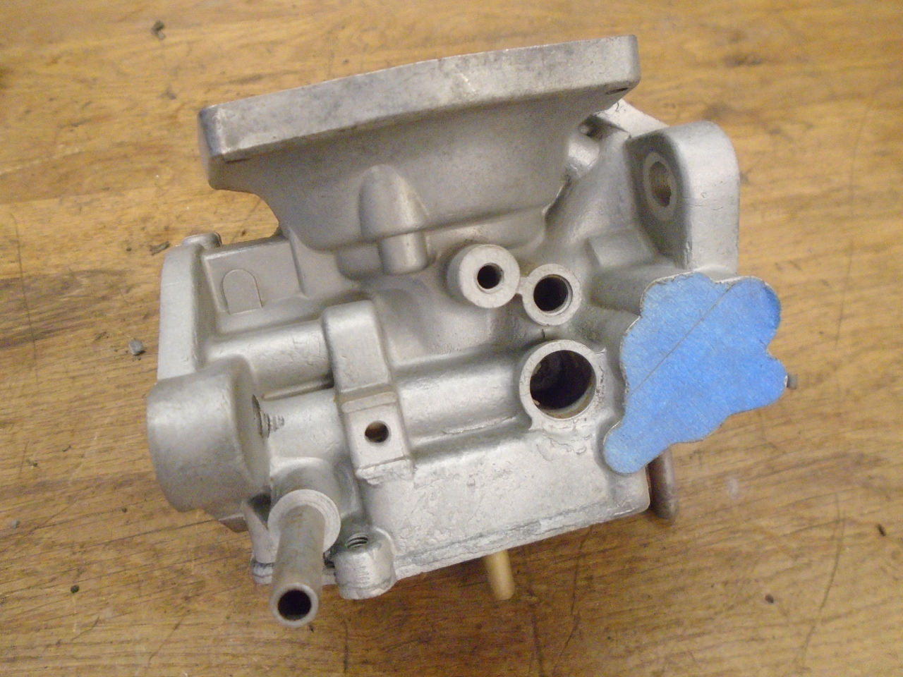
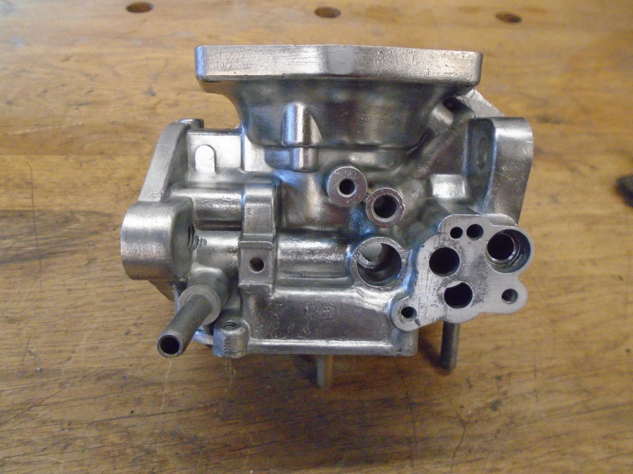
A light, low pressure blast with very fine grit cleaned up the
castings pretty well. With a little effort, the parts can
even be polished. I decided I didn't really like the
shined-up look, so I re-blasted them to get them back to the
more matte finish.
I worked on the sub-assemblies one at a time. First up was
the cold start valve. This valve adds fuel to the air
stream to help start the engine in cold weather. It does
what a choke does, but instead of restricting air, it adds
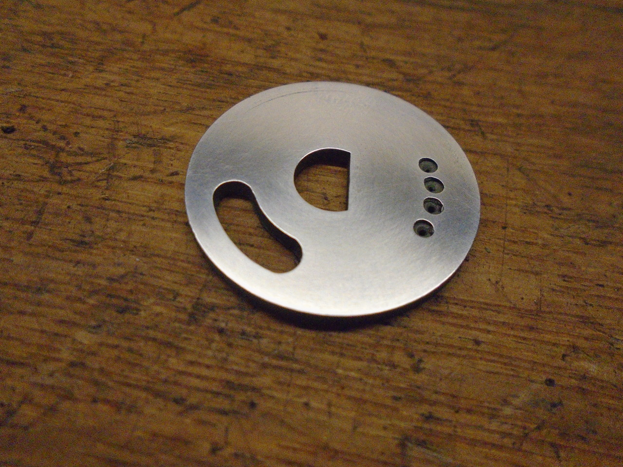
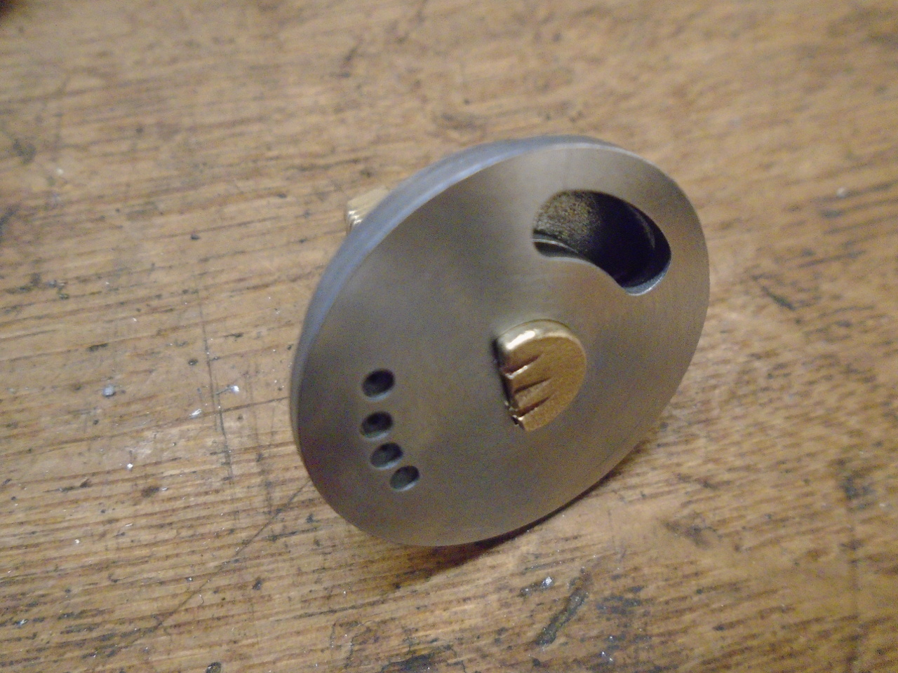
fuel. The fuel is metered by a disk with a series of small
orifices. The disk is rotated by a manual cockpit control
so that the orifices sequentially align with an opening in the
body.
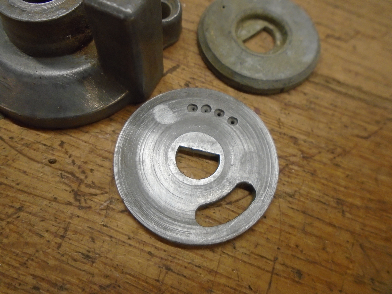
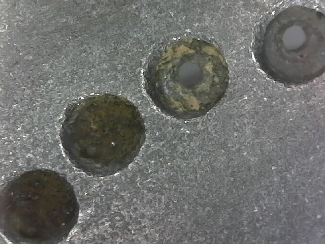
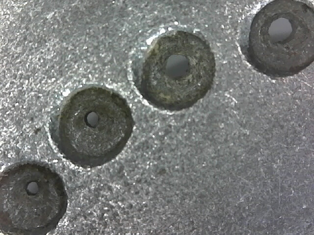
The orifices range from about 0.030" for the largest to maybe
0.010" for the smallest. Looking closely, even after a
pretty good cleaning, the smaller orifices were still
clogged. It took some concentrated effort to clear all of
the holes.
The disk had some visible wear marks, which cleaned up well by
linishing on a flat surface.
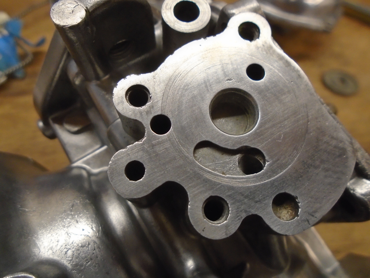
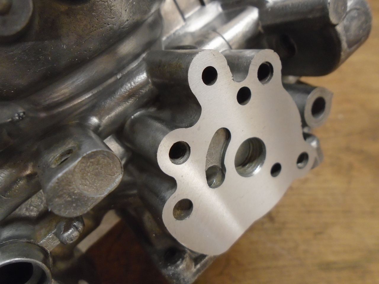
The mating surface on the body also had significant wear.
It took about a 0.005" surfacing to clean it up.
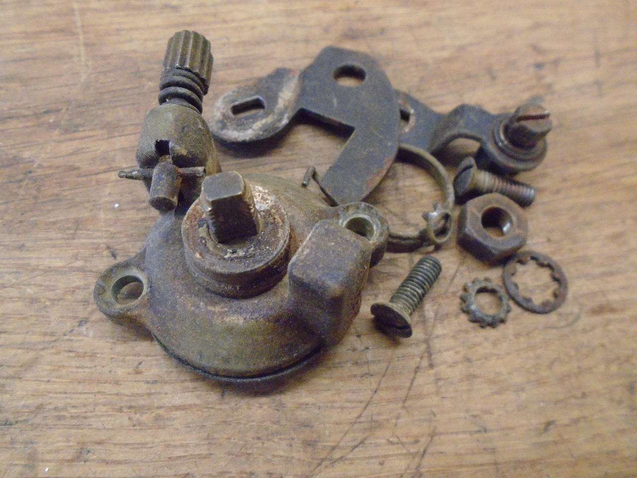
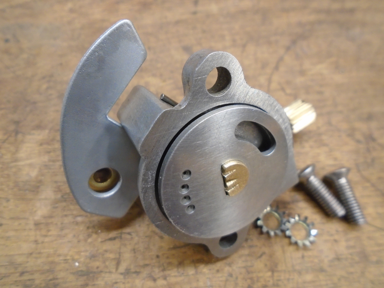
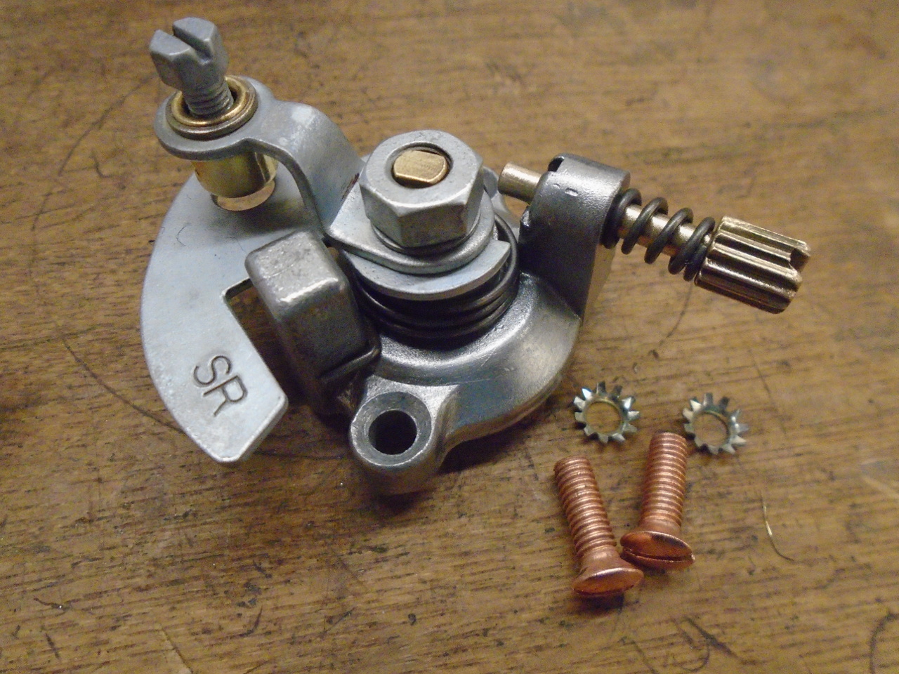
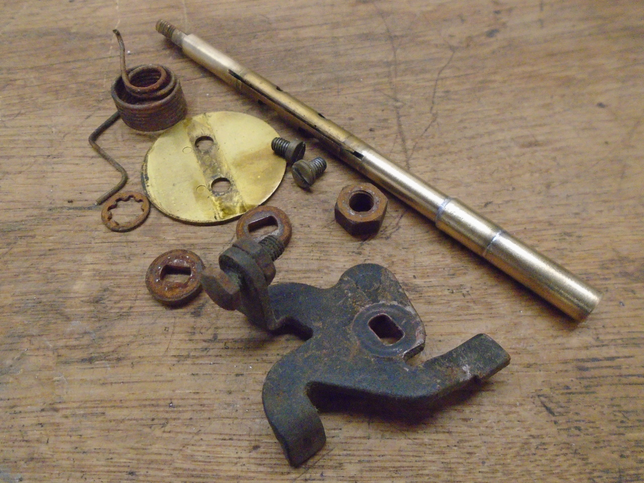
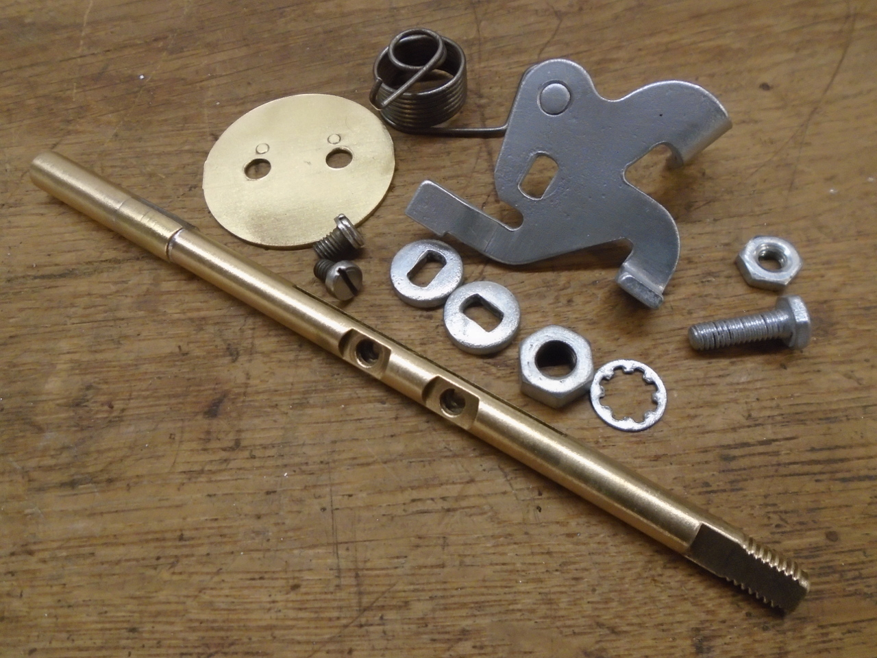
All of the parts for the cold start valve. Most of the
steel parts were stripped and re-plated.
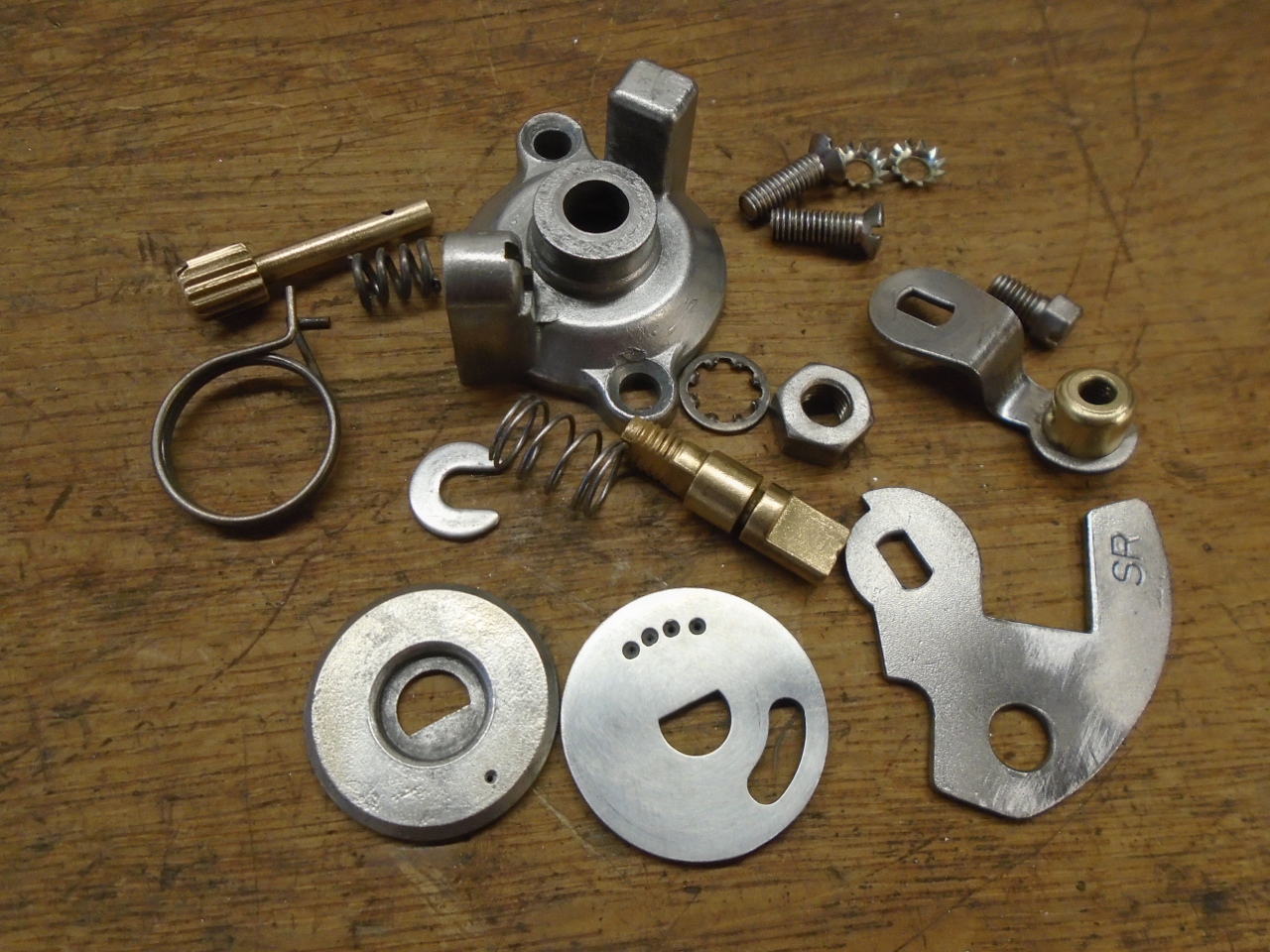
The disk gets staked to the little brass spindle.
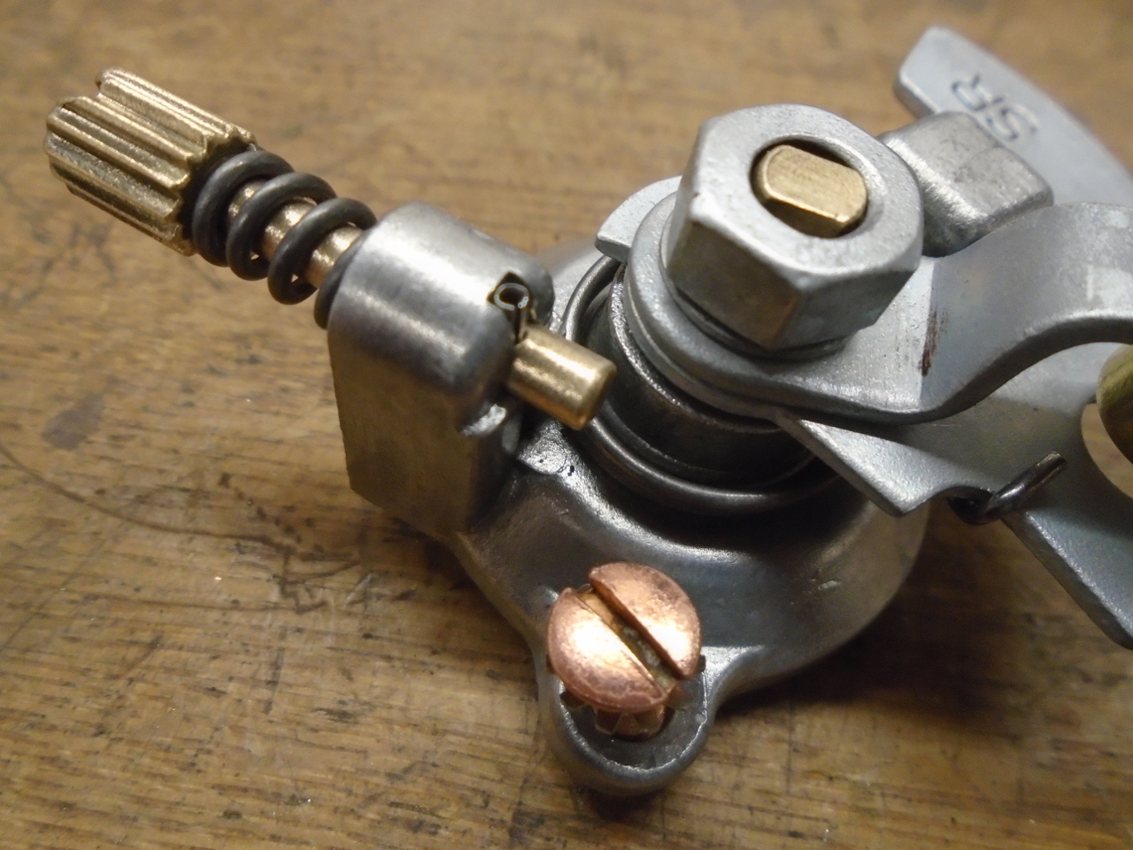
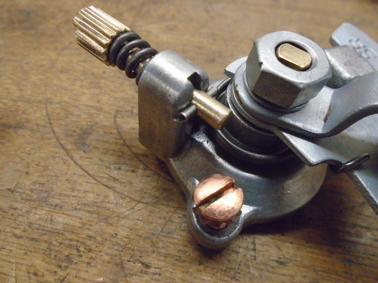
The finished cold start valve. I don't know why the
original mounting screws were copper plated, but they look cool.
Here's something I didn't know before this exercise. There
is a brass stop that limits the travel on the disk. The
stop has two positions: one for Winter, and one for
Summer, the Winter position allowing for a little more travel,
and presumably a little more additional fuel. Since
Nebraska winter roads are no place for a GT6, I'll leave mine in
the Summer position.
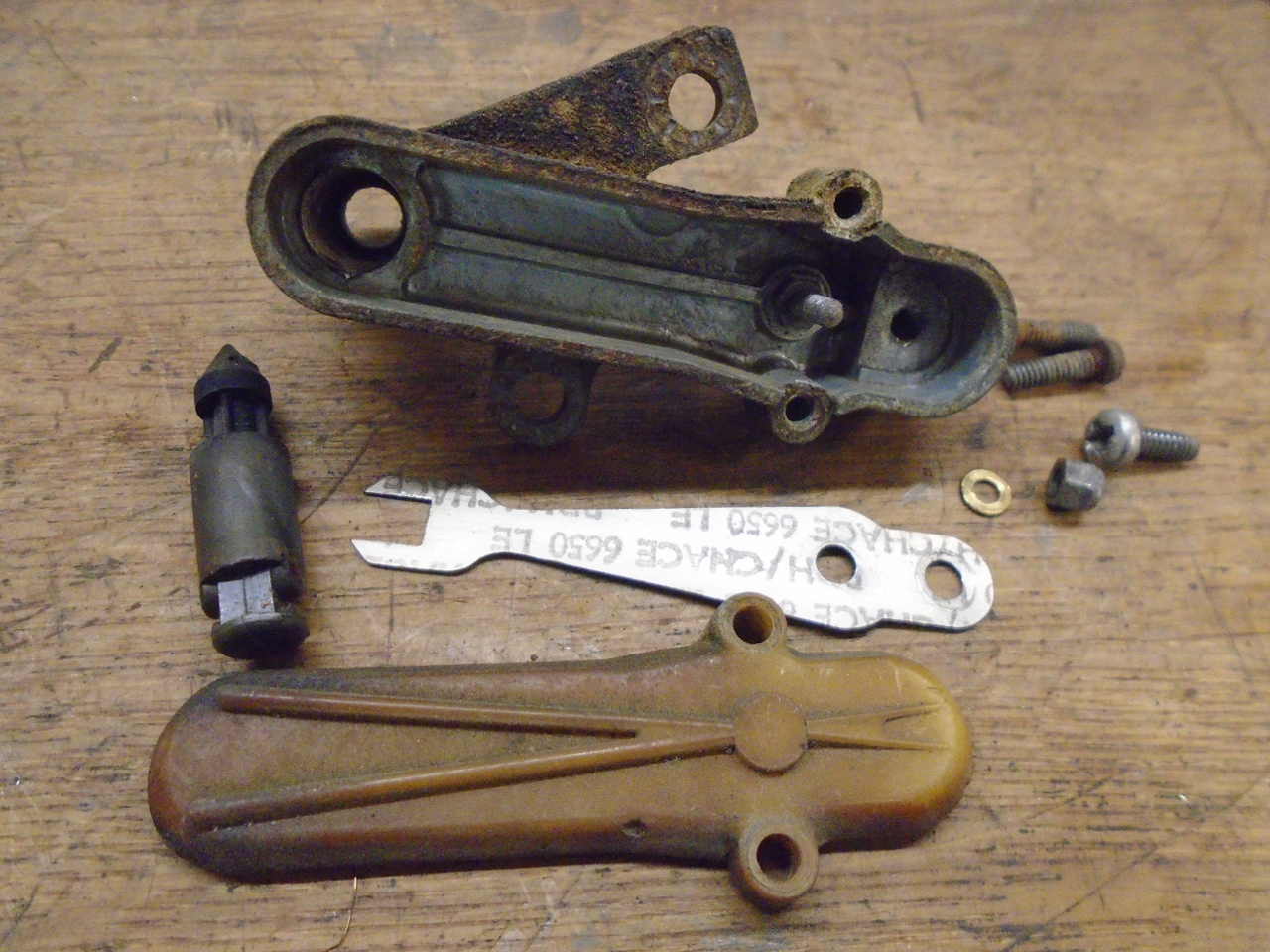
The first of the explicit emissions devices were the temperature
compensators. These long skinny devices contain a bi-metal
strips inside that open valves when they get hot. The
valve allows air to bypass the venturi, effectively weakening
the mixture.
After 50 years, I didn't expect that these units were likely
still in spec. I've not found any official guidance on the
set points for these goodies, but there is some knowledgeable
advice out there that says that that the valves should be closed
below about 115॰F, and open above 140॰F,
but also that the valves tracking each other is more important
than the actual temp points. (Both compensators have s
"60" stamped on their mounting wings. This might mean 60॰C,
which is 140॰F.)
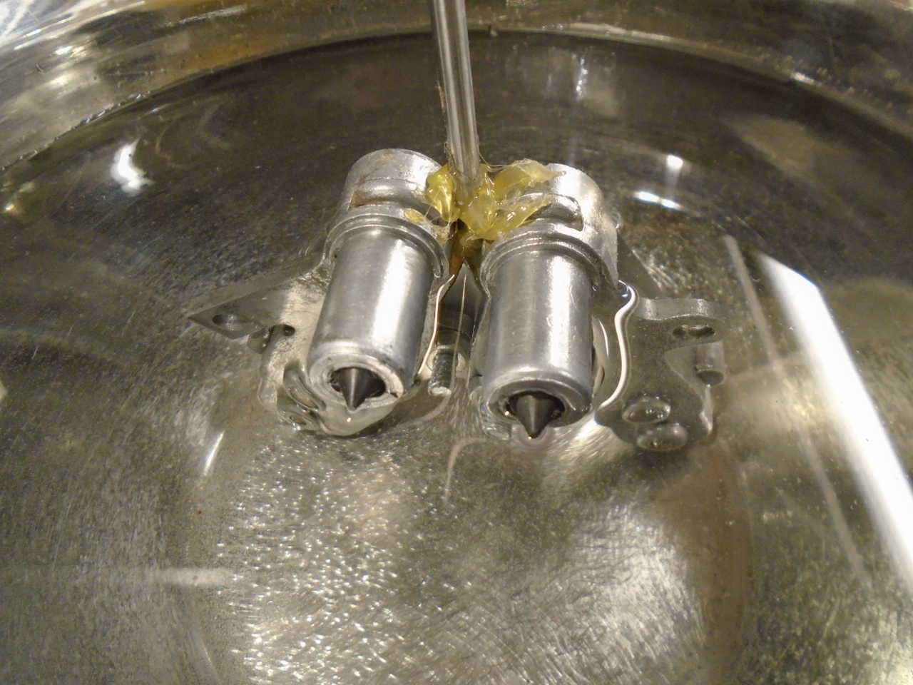
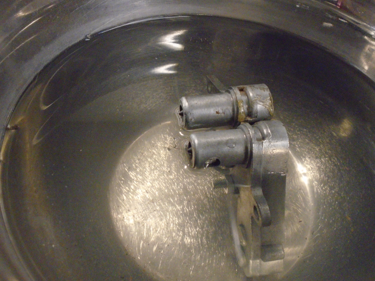
To test and adjust my compensators, I made this little
contraption. The long thing is a thermometer.
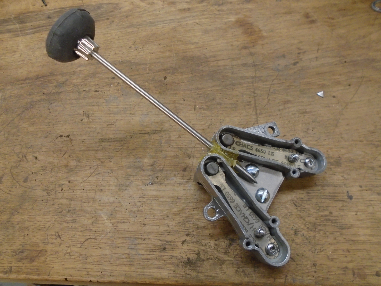
Then into a pot of water on a hot plate. The pics show the
valves closed and open. It took a few rounds of adjustment
to get them to track well and be close to the desired set
points.
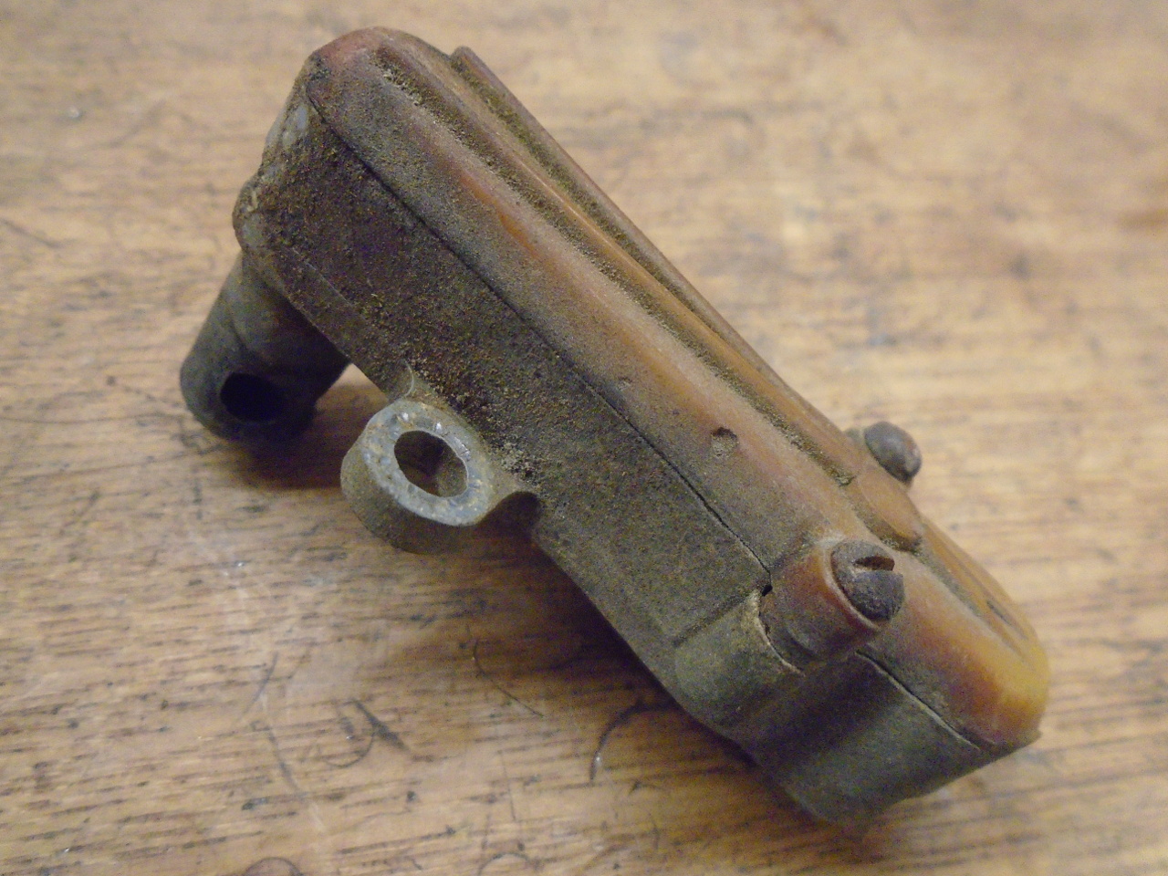
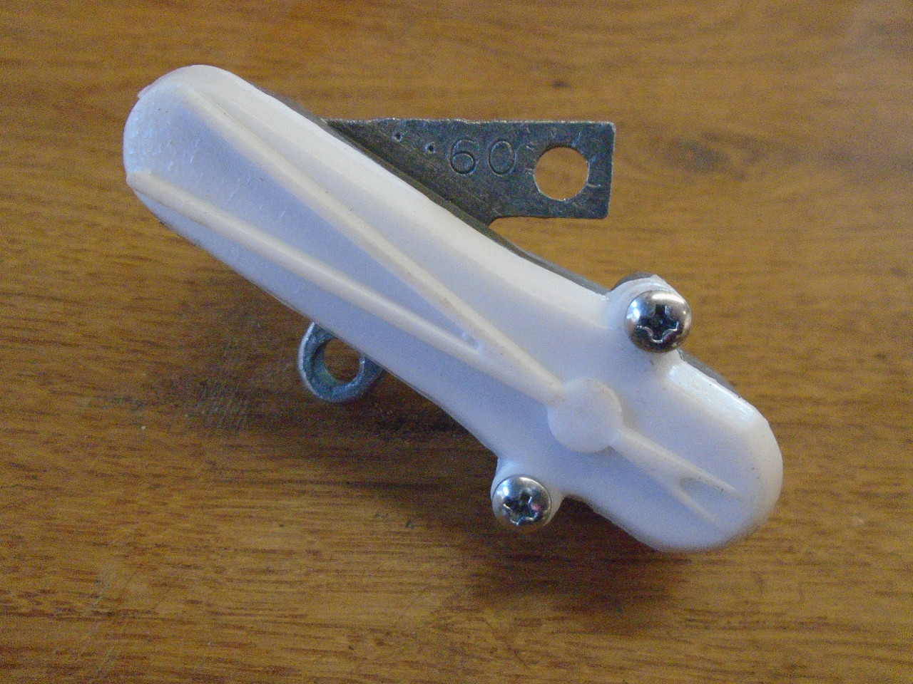
So here is one of the compensators ready for install. The
once-white plastic cap looked a little tacky, though.
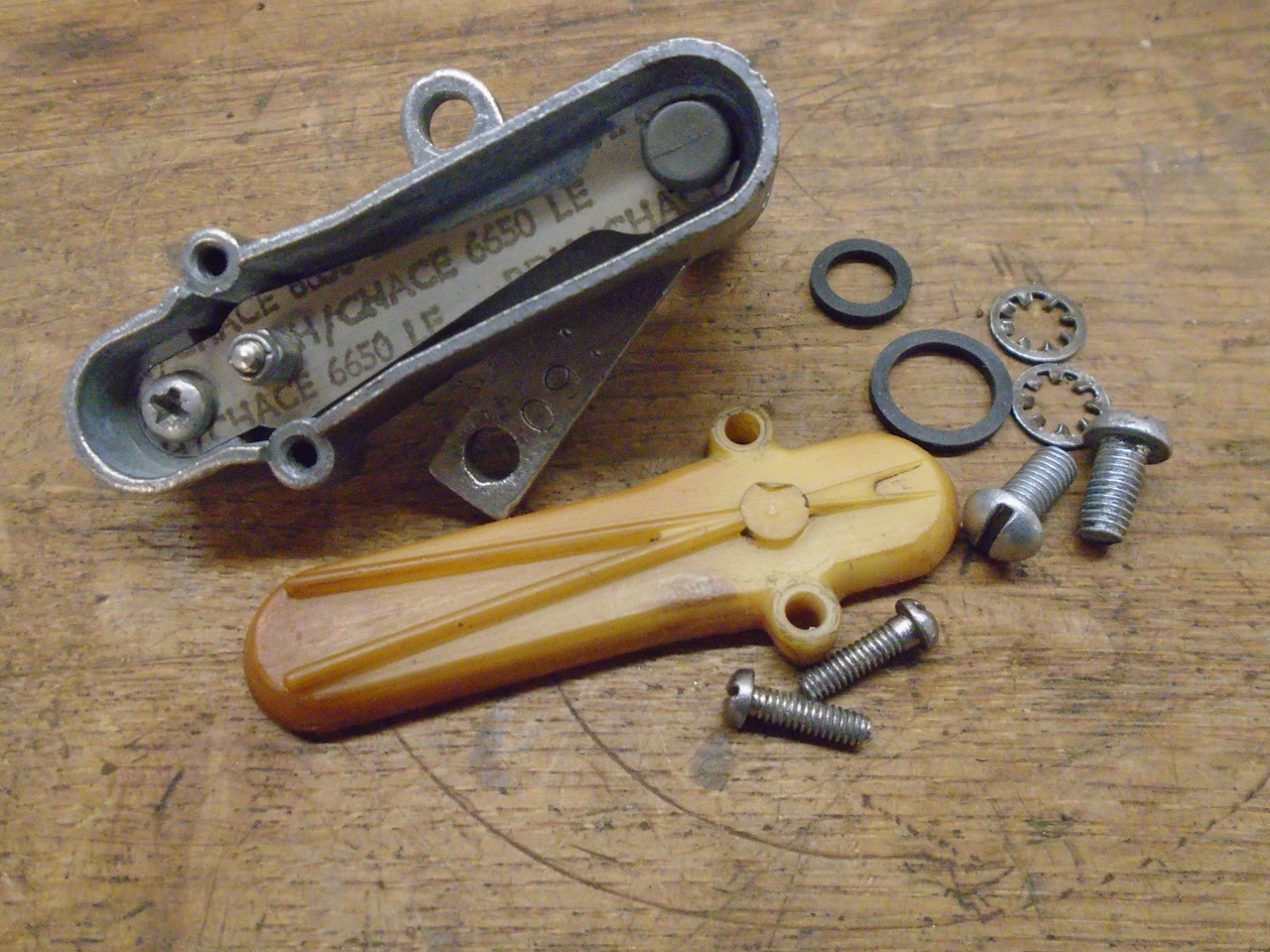
I realize these caps can be bought new for around $12 or so, but
they seem like something that might be interesting to make at
home. I considered 3D printing them, but there is a thin
locating lip on the inside that seemed a little too delicate for
a 3D print. I've always wanted to try my hand at resin
casting small parts, and this seemed like an ideal part to
experiment with. So, I made a two cavity silicone mold
from the originals, poured in some epoxy resin, and out popped a
couple of pretty good reproductions of the originals. I
made a set for the TR6, too, and the $50 or so that I saved just
covered the materials, and I have a lot left over.
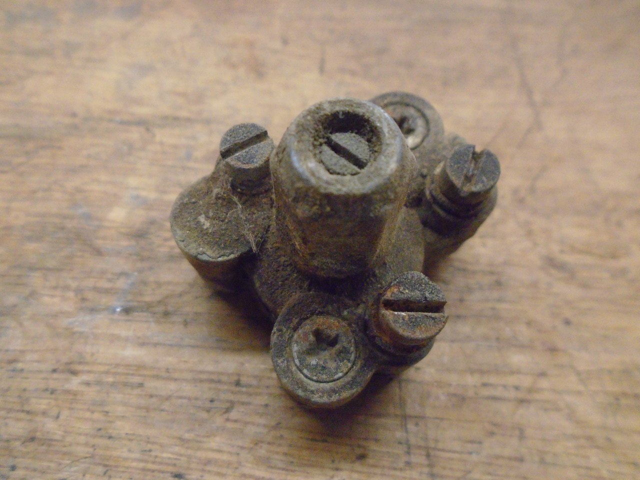
Next up was the so-called bypass valve. The bypass valve
is opened by a vacuum signal coming from the manifold side of
the throttle plate. With sufficient vacuum, the valve
opens, and passes mixture around the throttle plate. In
effect, this mimics a slightly open throttle, which limits the
vacuum that can exist in the manifold. The bypass would normally
operate during engine over-run conditions.
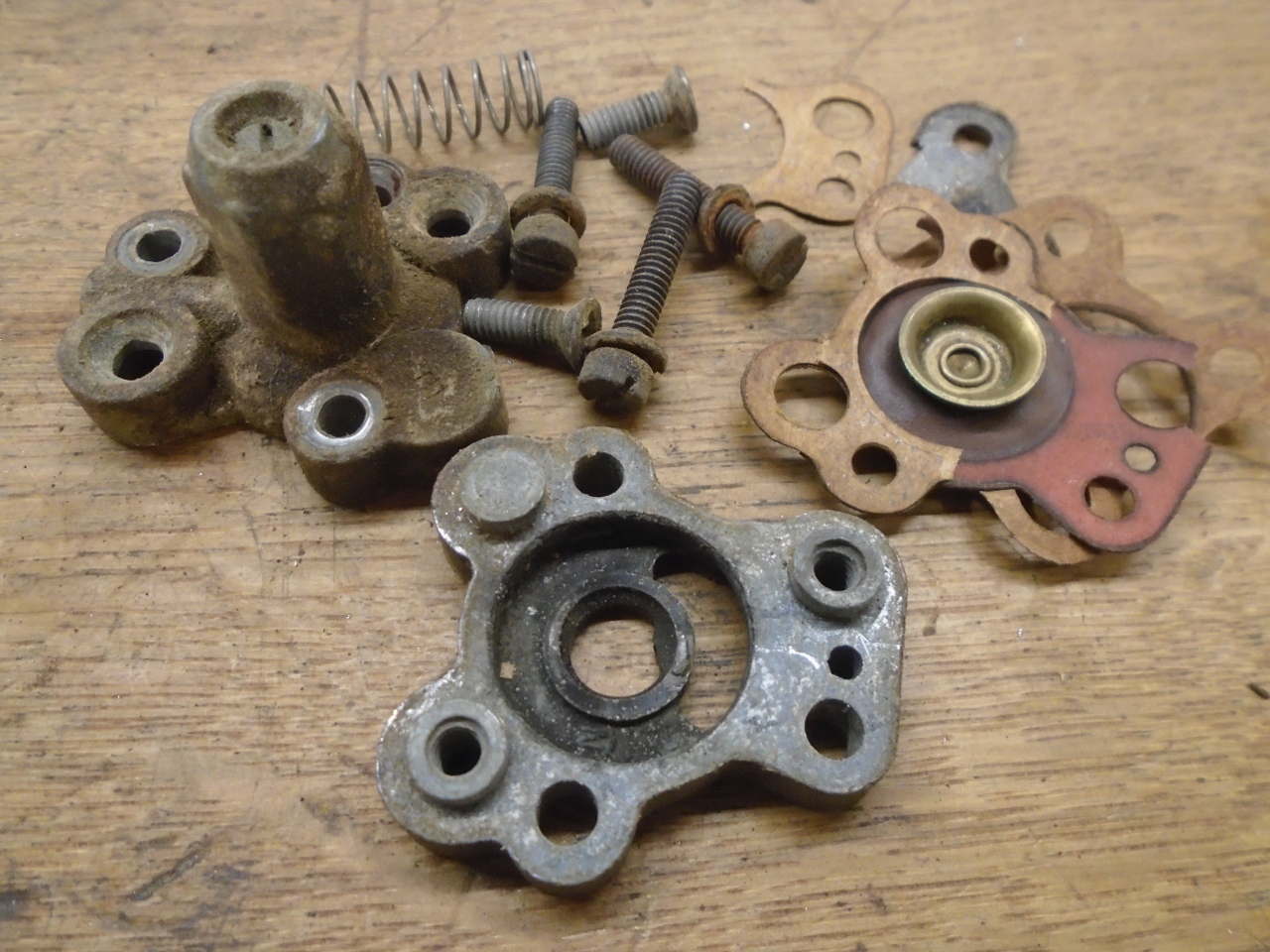
I made a considered exception to my own guidelines in the case
of the bypass valve. It was going to be around $30 for the
two rebuild kits. It didn't seem like money well spent on
something I intended to defeat. After cleaning up all of
the parts, my plan was to assemble the unit without the
diaphragm and add a blanking gasket between the valve assembly
and carb body. In the end, I had to install the old
diaphragm, since it is the lower seat for the internal
spring. Keeping the spring and other internal parts in
place seemed to be a good way of knowing where they were.
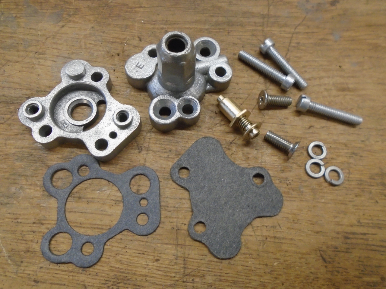
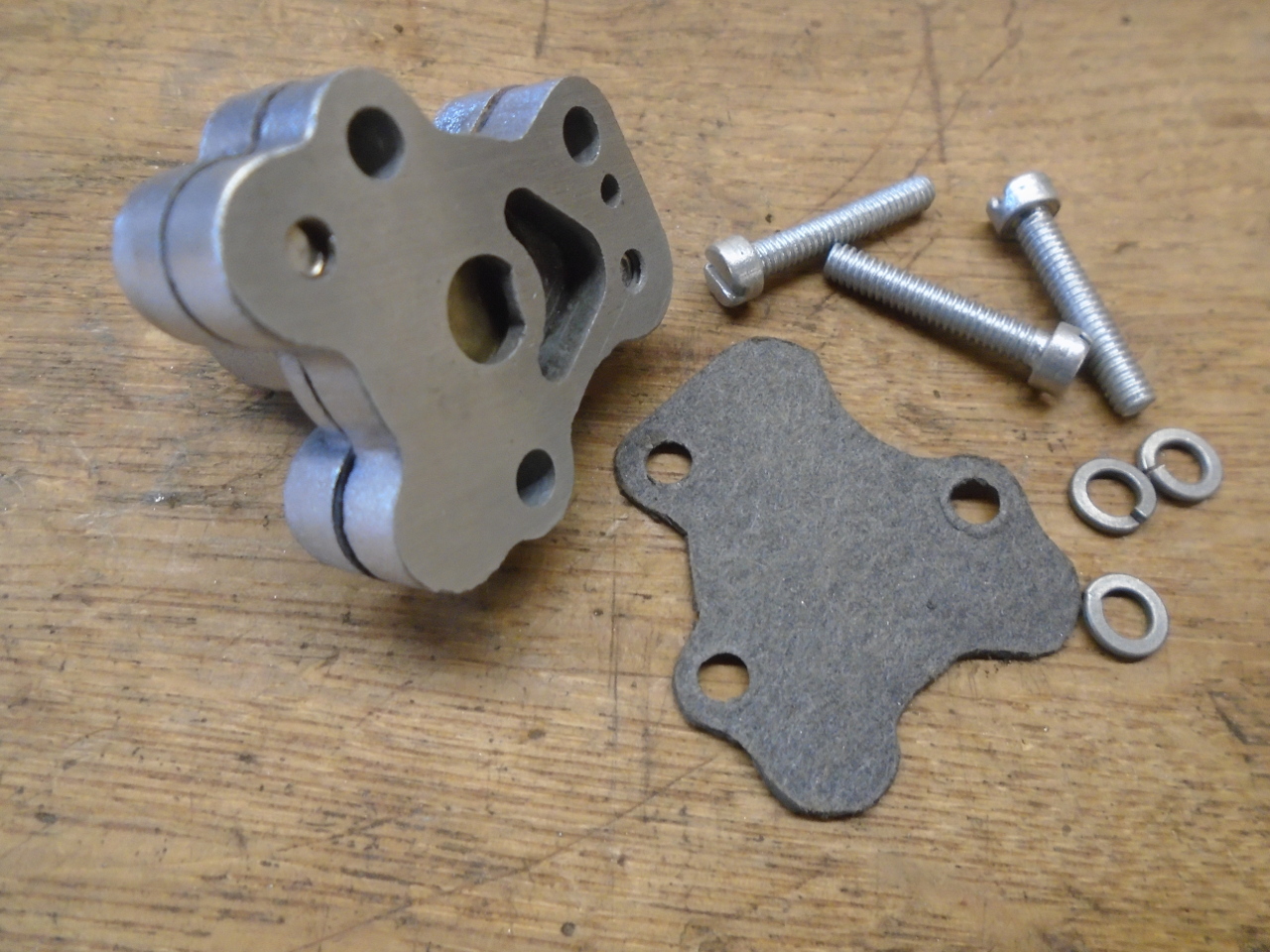
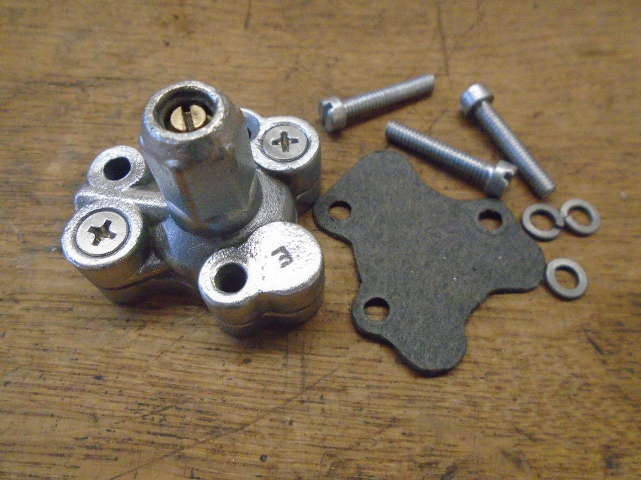
The seat on the body was a little rough, so I faced it off.
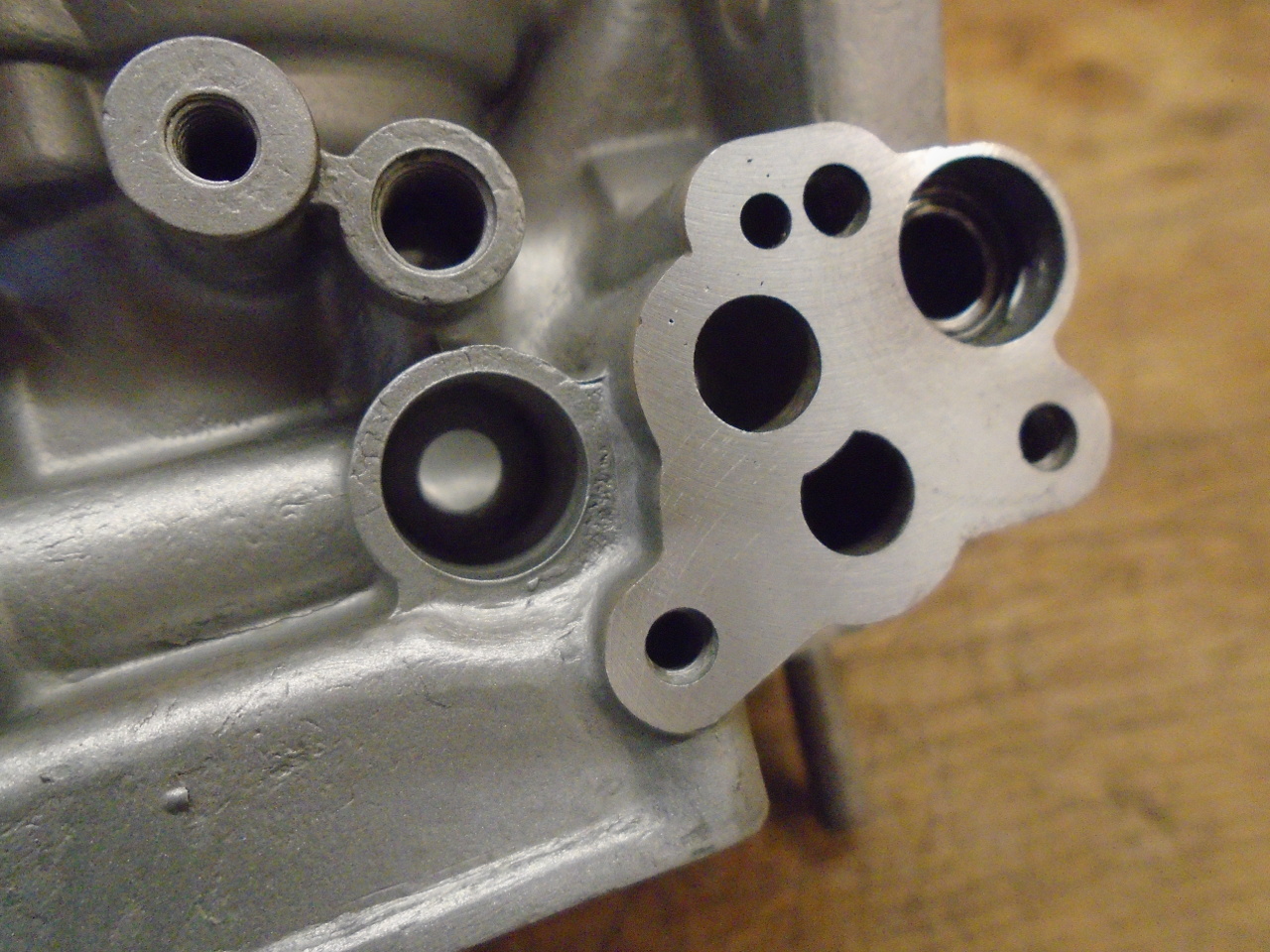
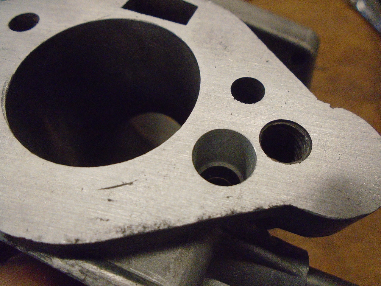
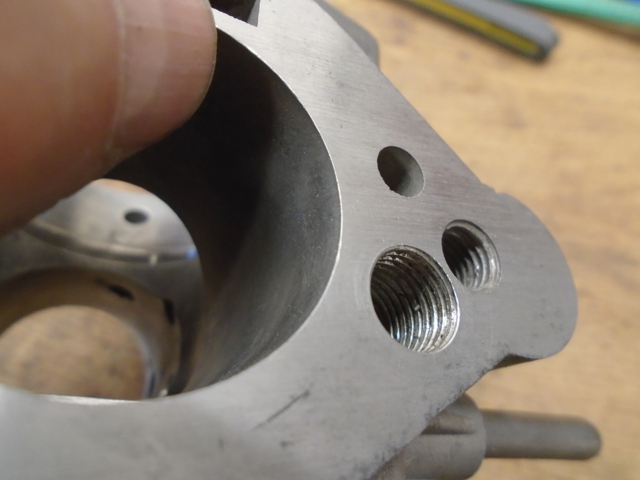
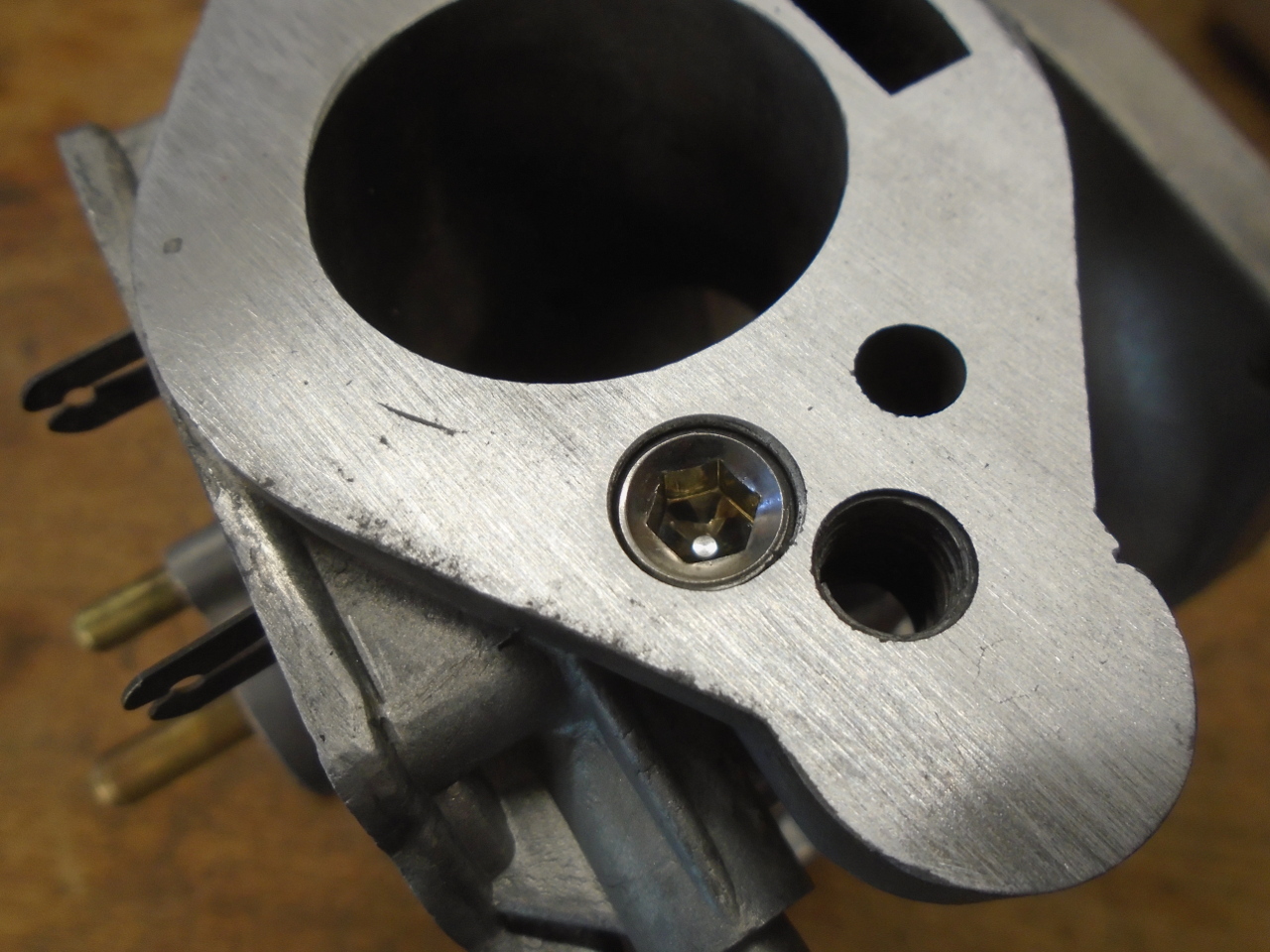
To disable the other emissions gear, namely the temperature
compensator and the idle trimming screw was simple since they
share an air supply port on the inlet flange of the carb.
I drilled and tapped for a 7/16-20 allen plug. It's a
nice, easily reversible mod.
The throttle assembly was next. Steel parts were replated.
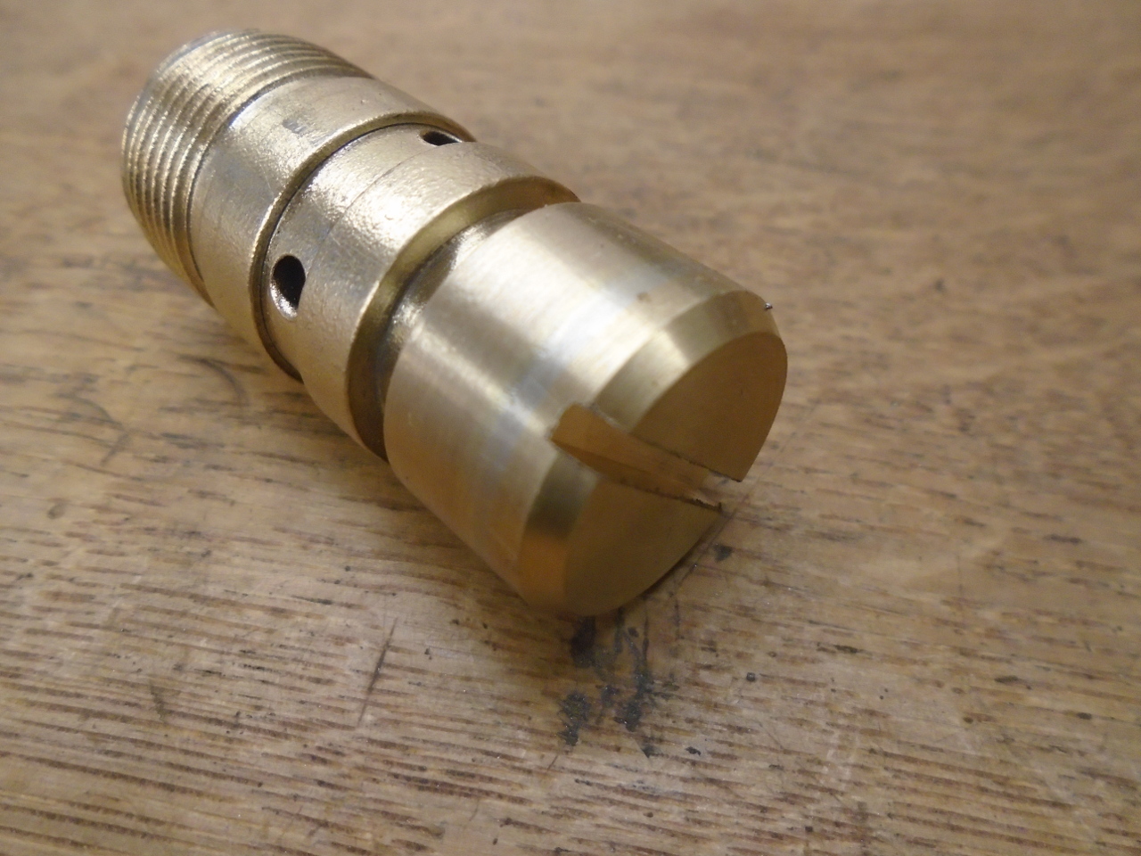
During disassembly, the float bowl on both carbs was seized to
the central plug. It took a fair amount of violence to
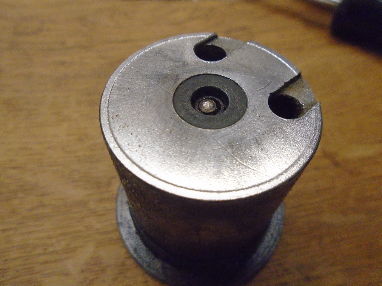
free the bowl, and in the process, the plugs were damaged.
This is the worst one.
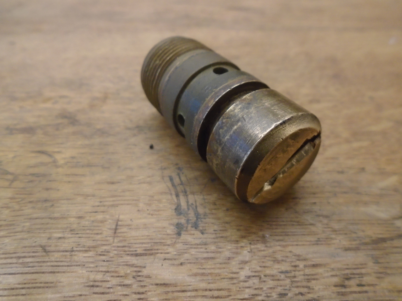
My solution was to turn down the damaged face, silver braze a
brass disk on, turn it true, and cut a new slot.
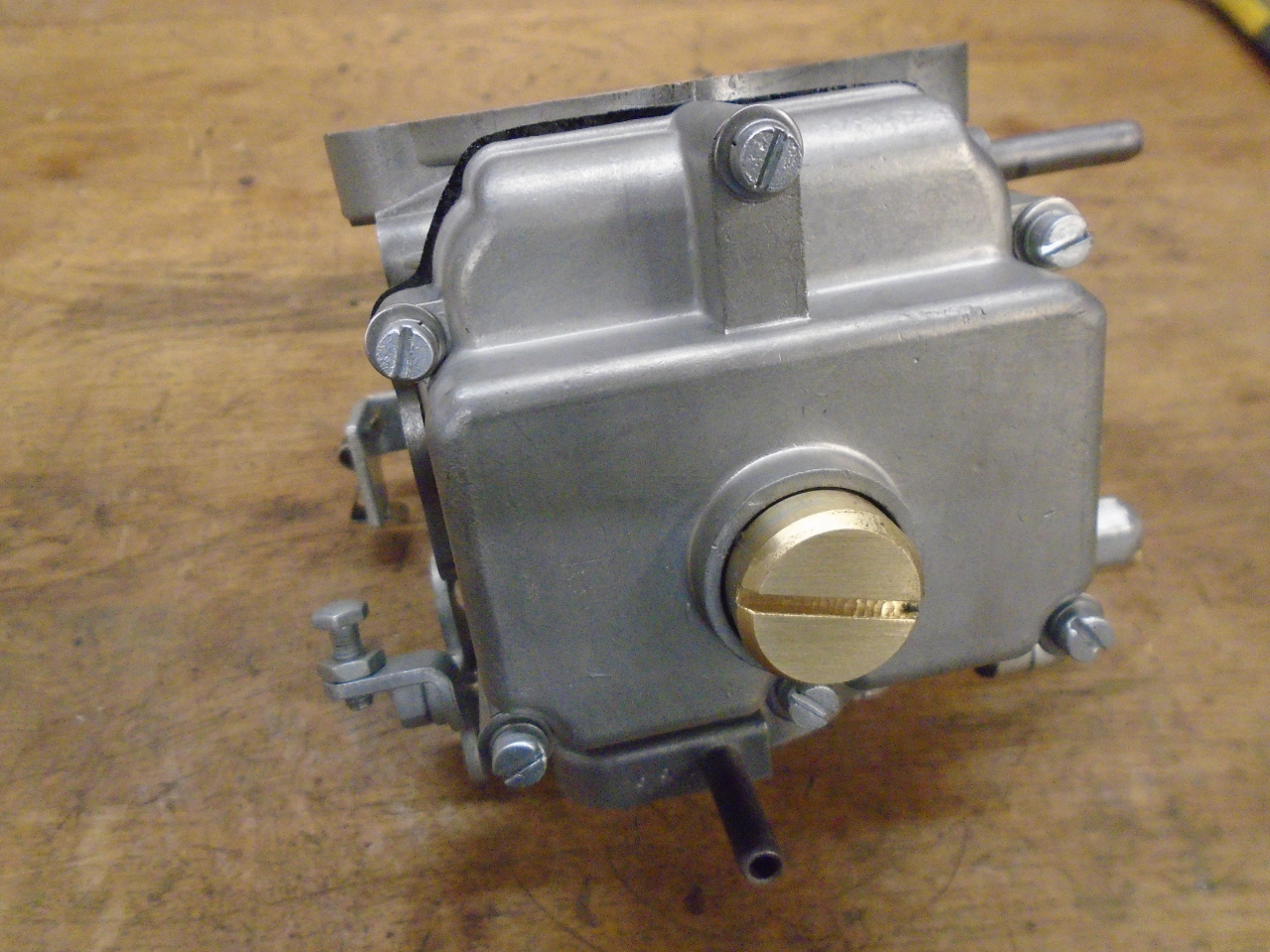
Then I was able to install the float, set the height, and
install the bowl.
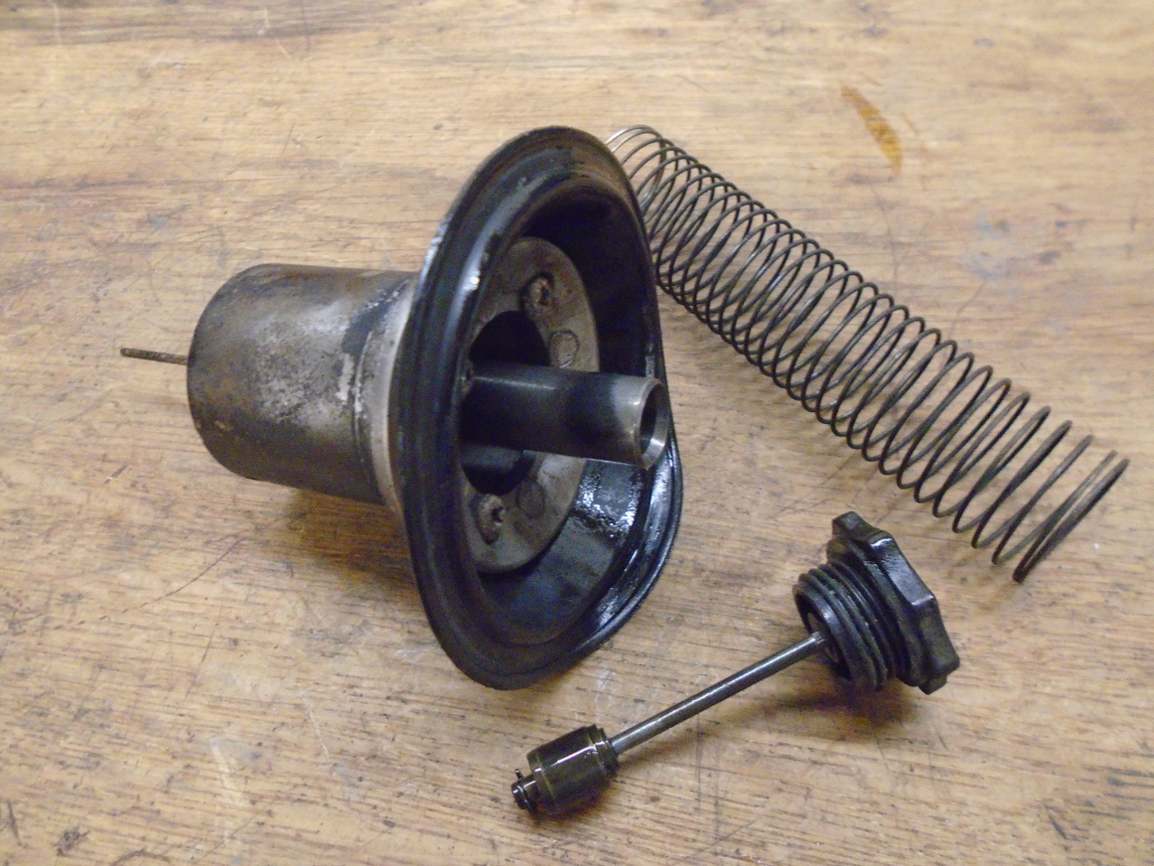
The main air valves on these carbs had fixed needles, and they
were both seized in place. It took a lot of heat, solvents
and persuasion to free them, but one got broken in the process.
After all of this, it was just final assembly with all new
gaskets and rubber parts, including throttle shaft seals and
main diaphragms. This brings me to the topic of rebuild
kits. I bought two well known, name brand kits from the
same vendor, but the kits were a little different. One had
a fiber washer for the damper cap, the other was rubber.
One was short the little brass cups for the throttle shaft
seals. One had two different gaskets for the float bowl,
the other only had one. The needle valves were different:
one was imperial, one was metric. Beyond this, I only
needed a fraction of the parts in the kits. The left over
parts were different for the two kits. All trifles, maybe,
but I considered the kits fairly expensive at over $40 each, and
expected something a little more tailored to my application.
I did one carb first, to keep the other as reference.
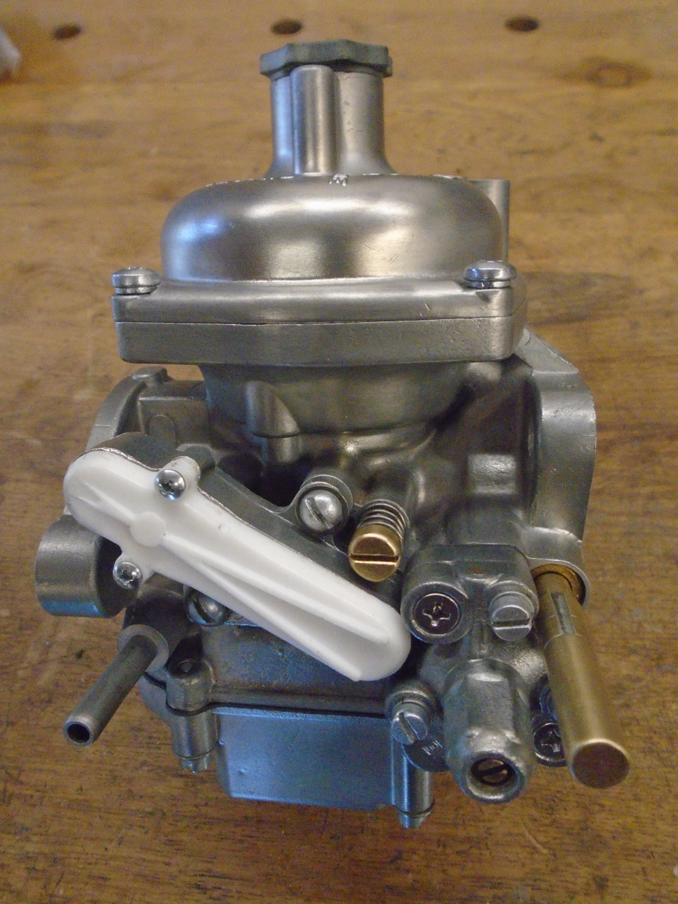
The other one went a lot faster.
On the shelf until another day.
These carbs were pretty similar to the TR6 carbs I did a few
years ago, so this wasn't an all new experience. Cost was
around $120 for the rebuild kits, the new needle, and the
casting stuff for the compensator covers.
It was finicky work at times, but made for a few pleasant
afternoons in the shop.
Comments to Ed at elhollin1@yahoo.com
To my other GT6
pages.