To my other GT6
pages
December 29, 2019
Fuel Pump
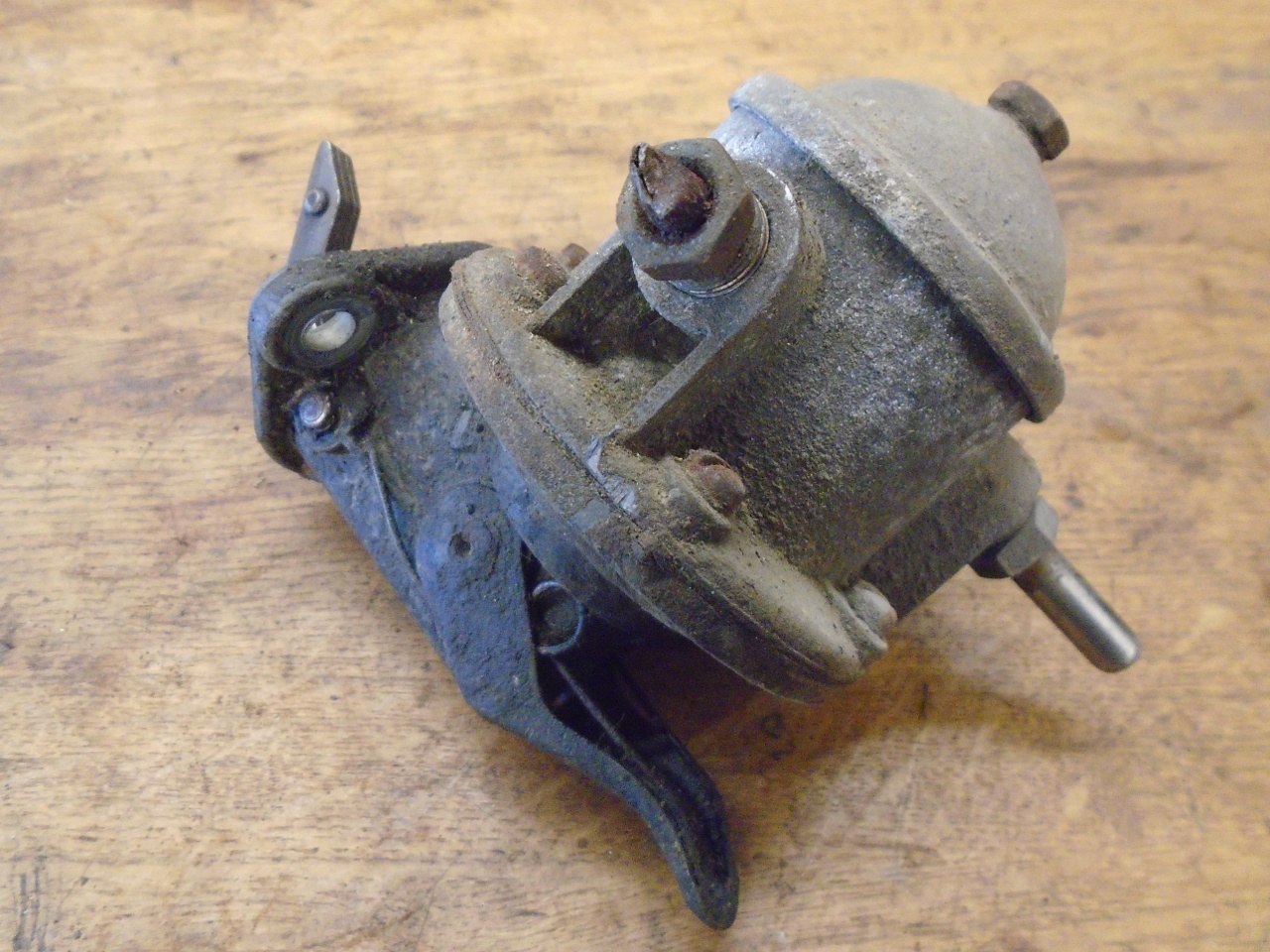
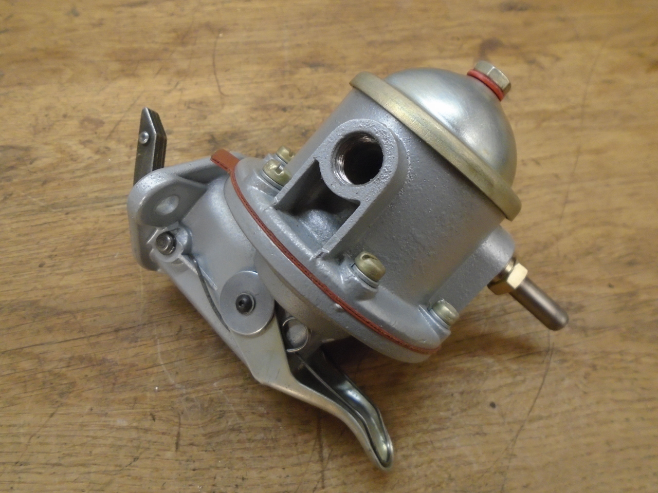
The AC fuel pump as found on my GT6, and a few variants, were
pretty commonly used on a range of British cars of the era.
This pump is probably original, or at least a period replacement.
Though reproduction pumps are easily available, there is always
the nagging question of the quality of aftermarket parts.
There are good quality replacements out there, but their cost
makes rebuilding the original an even more attractive option.
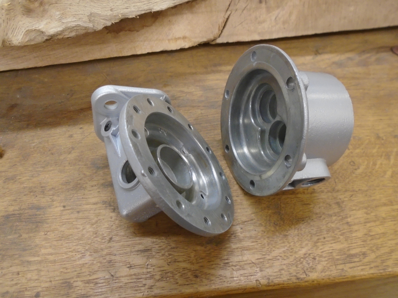
The main body of the pump consists of two pot metal castings held
together with six screws.
One area largely ignored by the rebuild kits is the priming lever
mechanism. With some diligence, it does come apart, and
there are some seals to tend to.
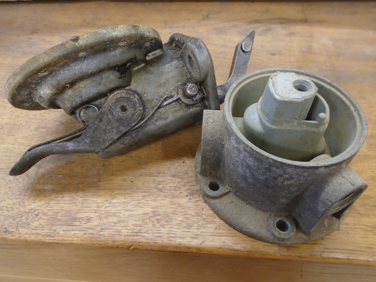
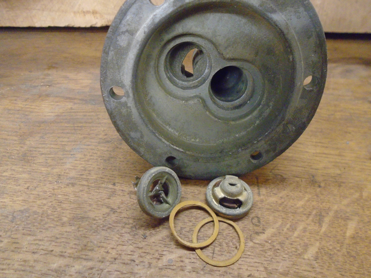
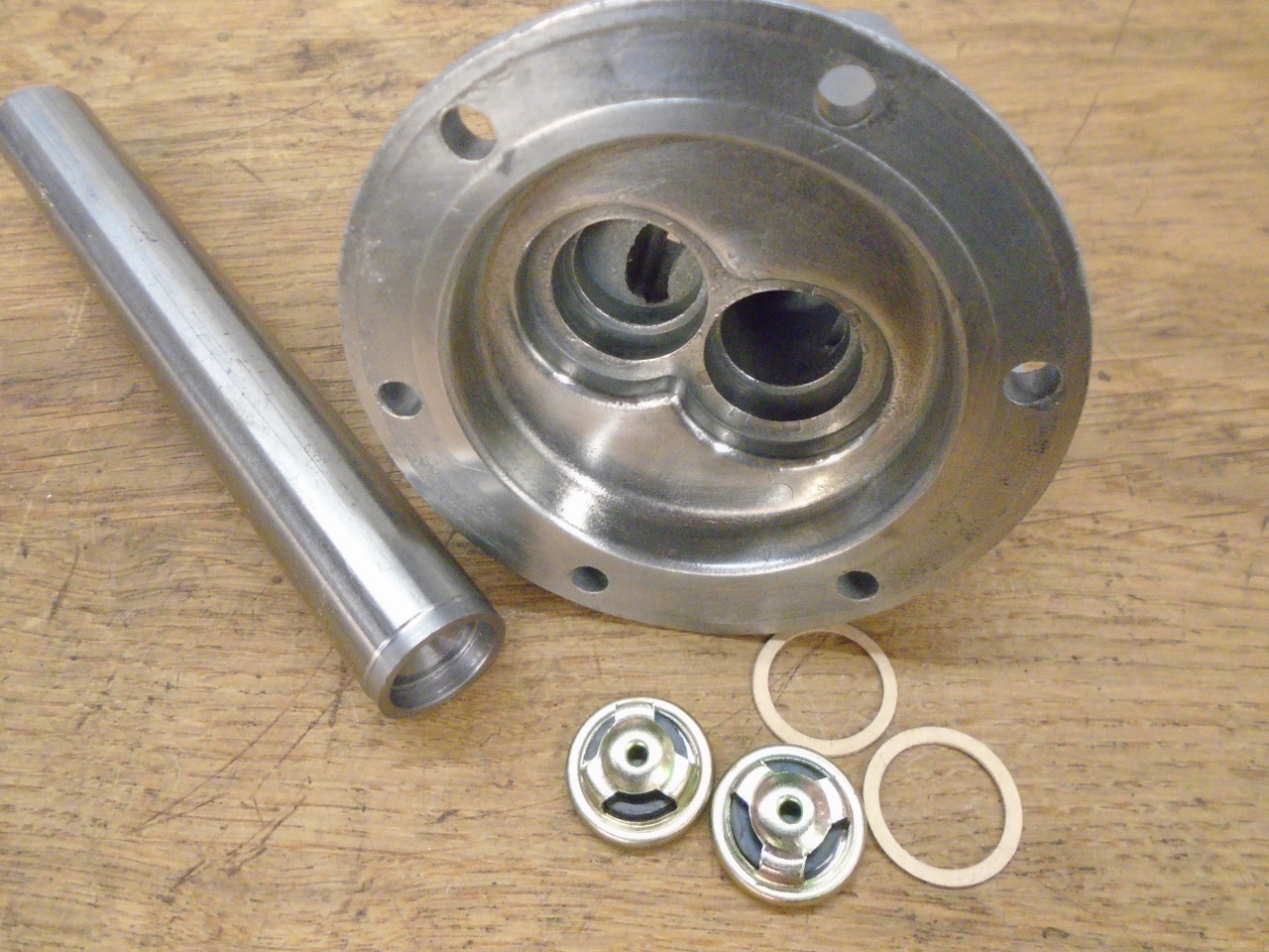
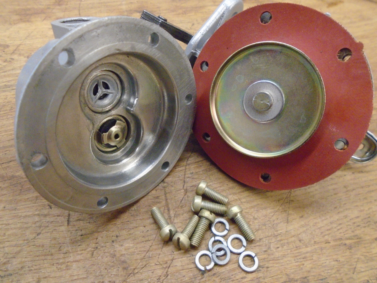
The top half of the body holds a pair of opposed check valves, one
lets fuel into the pump on the downstroke of the diaphragm, and
the other passes fuel out of the pump under a small
pressure. Sometimes these valves are staked in, and
sometimes there is a little metal retainer clip screwed to the
body. In this case, the check valves were just a friction
fit. One of them could be driven out from the top with a
drift, while the other had to be brutalized from the bottom side.
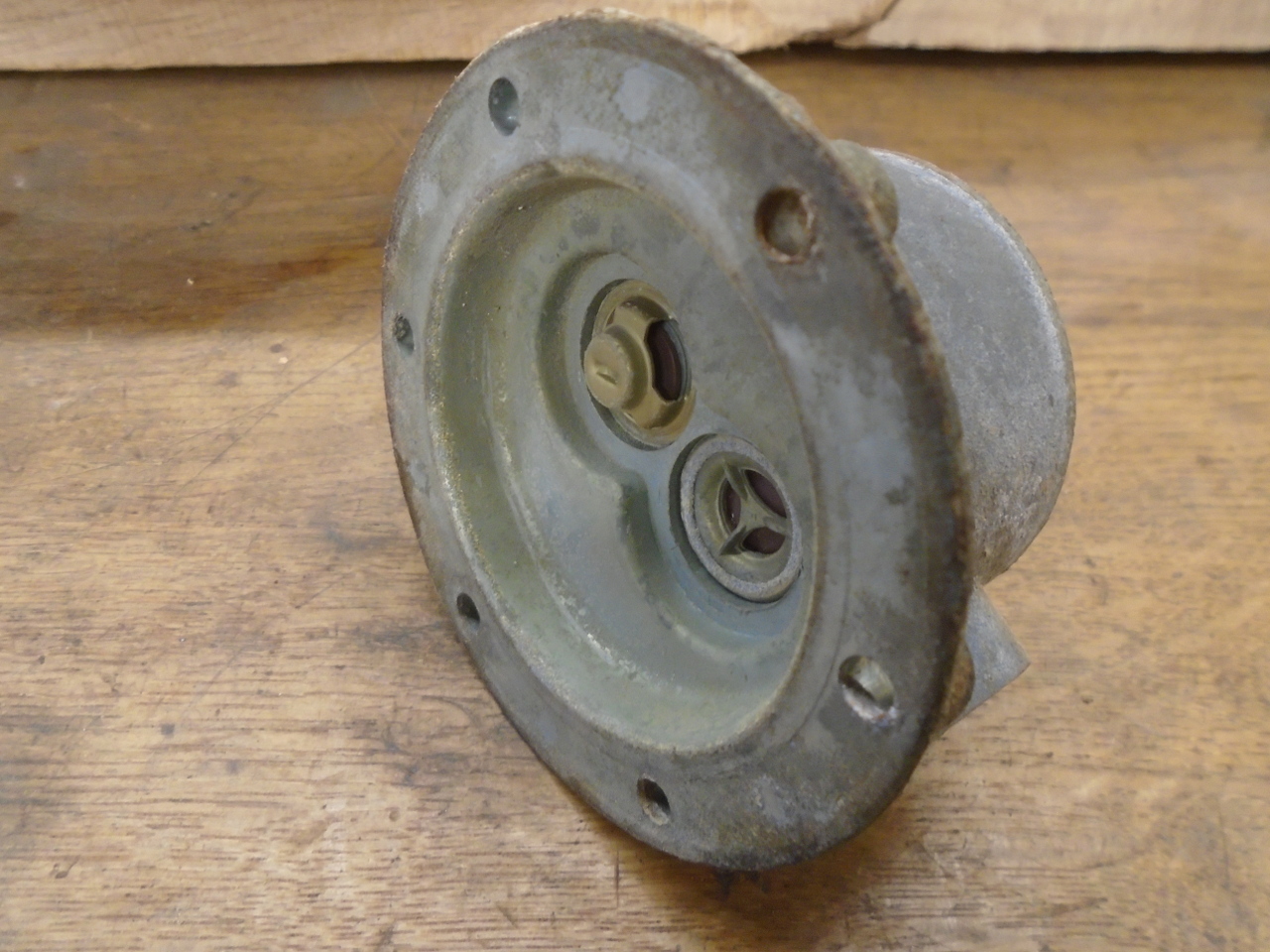
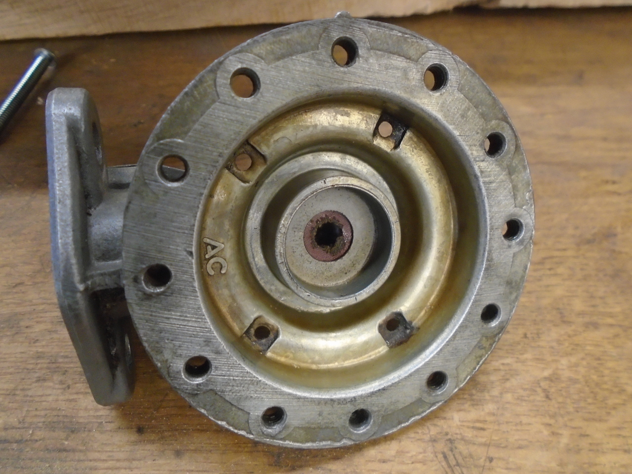
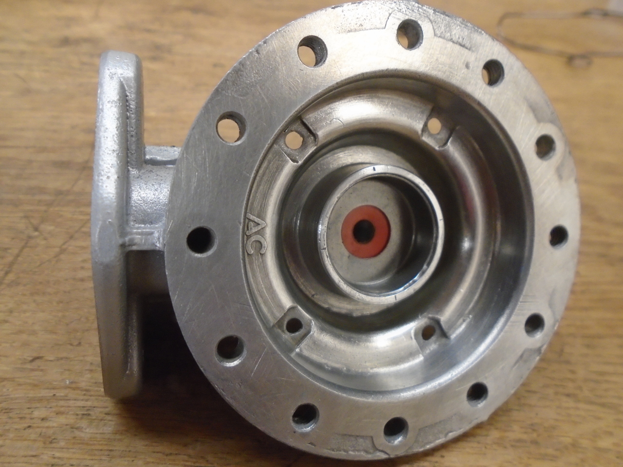
The bottom half of the body holds the lever mechanism to operate
the diaphragm, and also a seal for the diaphragm rod. The
seal allegedly separates the pump chamber below the diaphragm from
the crankcase to prevent fuel from entering the crankcase in the
event of a diaphragm breach. That could be true, but I have
my doubts. The lower pump chamber has a number of sizeable
vent holes in its floor, so most fuel would simply spill out of
the pump on to the ground and be pretty obvious. It is also
possible that the seal was to keep crankcase vapors out of
the pump. In any case, these seals seem to wear rapidly, and
are not typically included in rebuild kits, so many pumps out
there are operating without the benefits of this seal, whatever
they are.
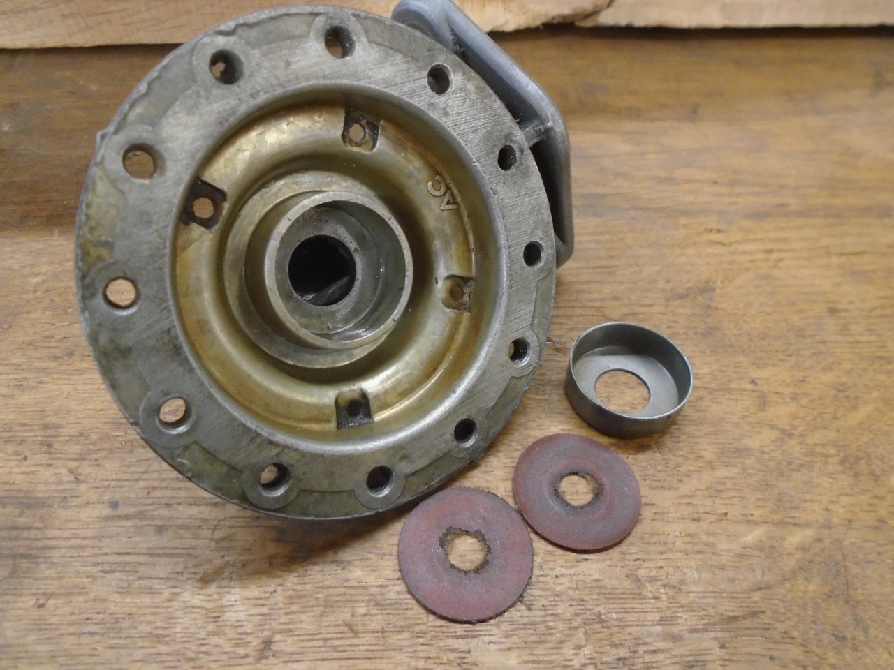
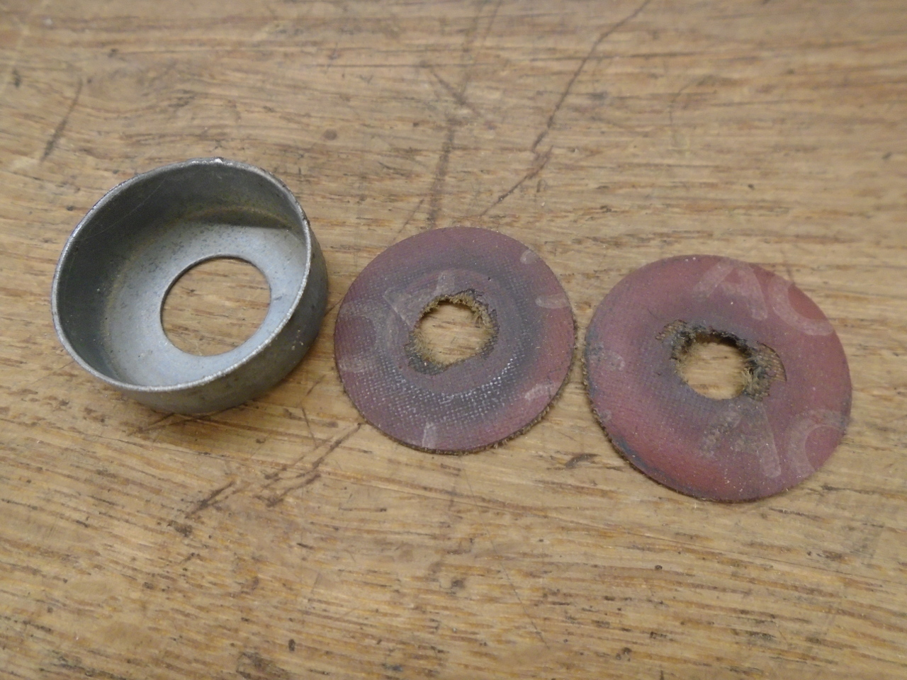
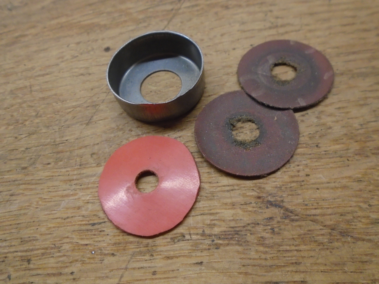
Though seal designs vary, the one on my pump consisted of a metal
cup which captured a couple of thin composition discs. The
discs appeared to be some sort of fabric reinforced resin
material, and were relatively stiff. At some time, they may
have been ore resilient, but in this condition, they were not
sealing anything.
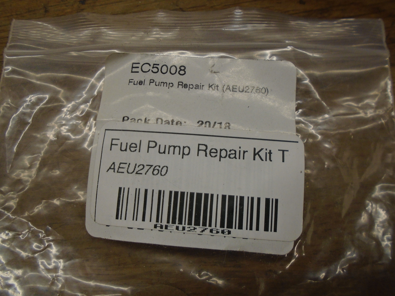
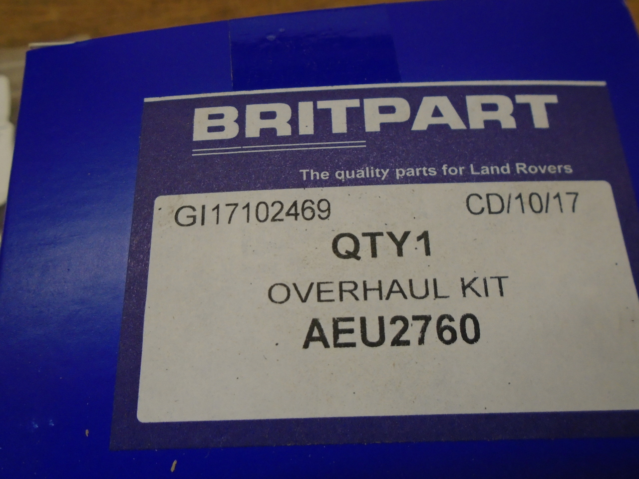
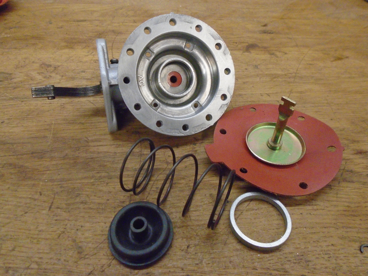
I found a funny thing about rebuild kits for these pumps.
They vary all over the map as to what is in them. The
universal part number for the kit is AEU2760. I had two of
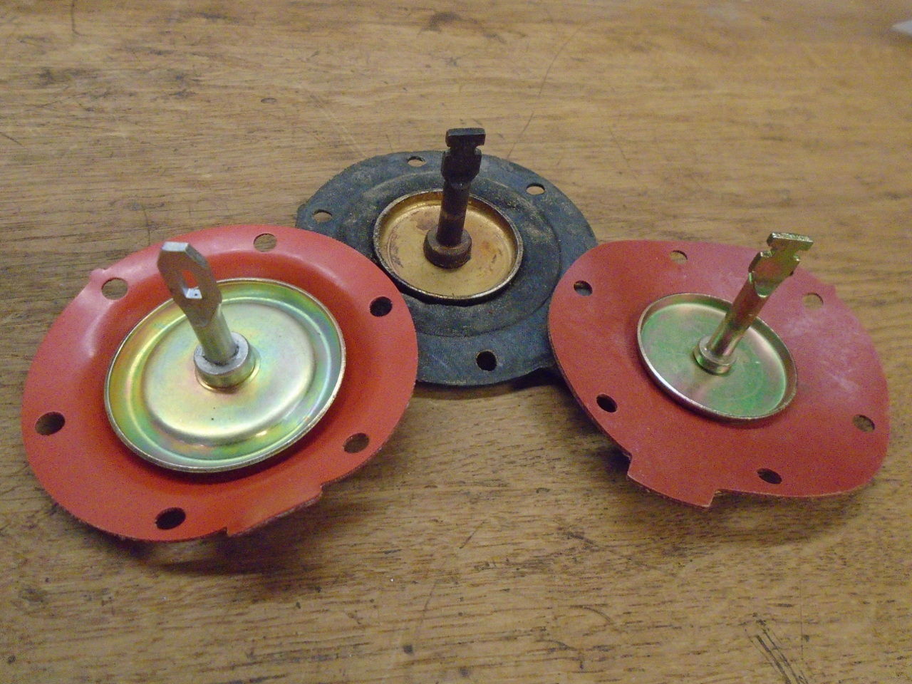
these kits from different sources. For example, the
diaphragm in one of the kits was quite a bit different from what I
needed. In the end, it took parts from both kits to get the
job done. The one in the blue box came from a Rover
supplier.
I started the actual rebuild process by cleaning up the castings,
linishing the mating surfaces flat, and powder coating the
outsides. With some effort, these pumps can be polished to
look amazing, but pot metal being what it is, the shine doesn't
last long.
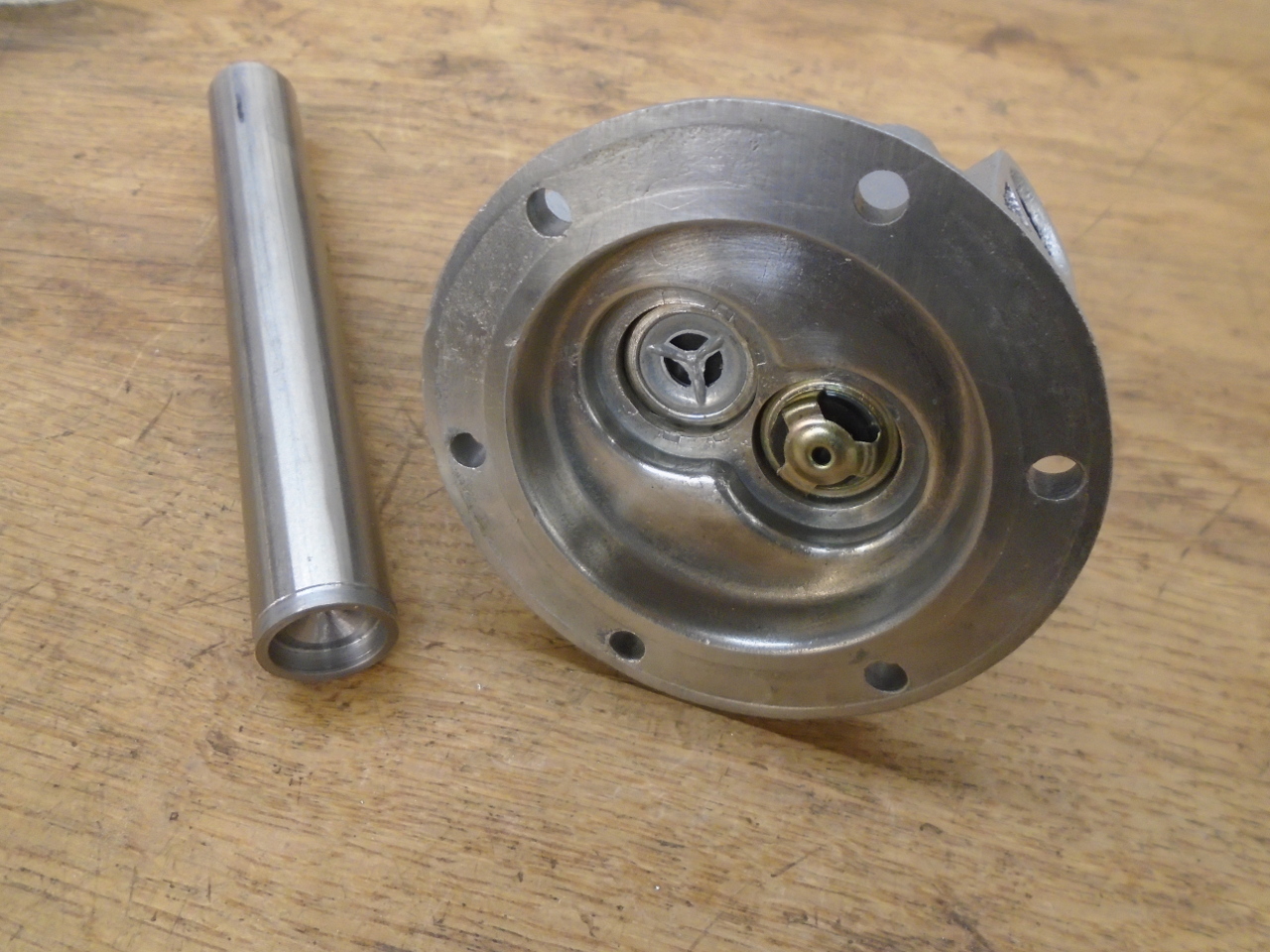
Next up was the check valve install. Since mine were a
friction fit, and some force would be required, I made the little
tool to help drive them in straight. Letting them get
distorted didn't seem like a good idea. Either or both of
these valves will happily go in the wrong way round. Of the
four possible permutations, only one will result in a working
pump.
I thought some about the stock diaphragm rod seal. Though I
doubted its effectiveness, and it was not included in either kit,
it seemed pretty easy to renew. I used a piece of fuel
resistant, fabric reinforced rubber about the same thickness as
the two original discs. The rod on my new diaphragm was
significantly smaller than the original, so I sized the hole
accordingly. The metal cup is pressed in such that the seal
can float slightly, so it can self-center.
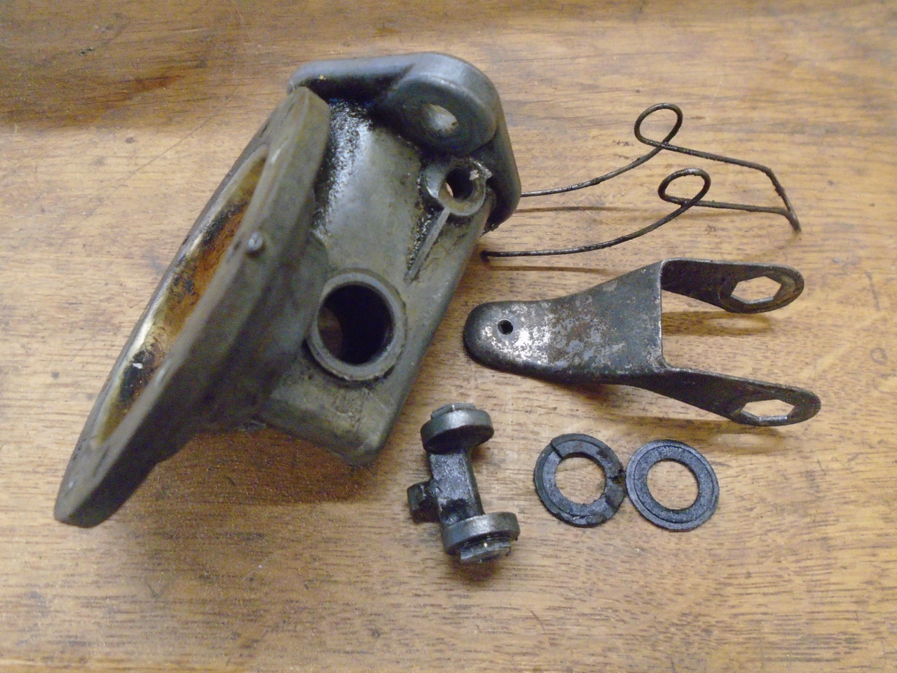
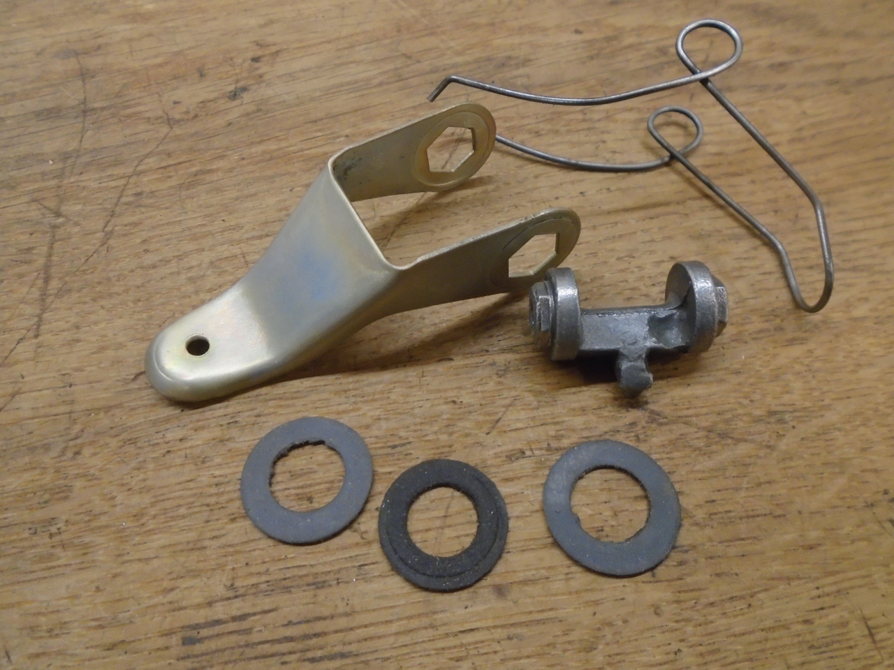
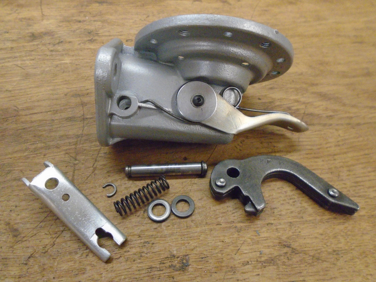
These are the parts of the priming lever arrangement. The
lever itself was stripped and replated. The original
washer/seal in the center appeared to be some slightly fibrous
material--maybe felt or severely aged rubber. The other two
are new ones cut from 0.032" rubber sheet. The spindle that
the lever attaches to shows a very visible casting defect. I
guess they thought no one would ever see it.
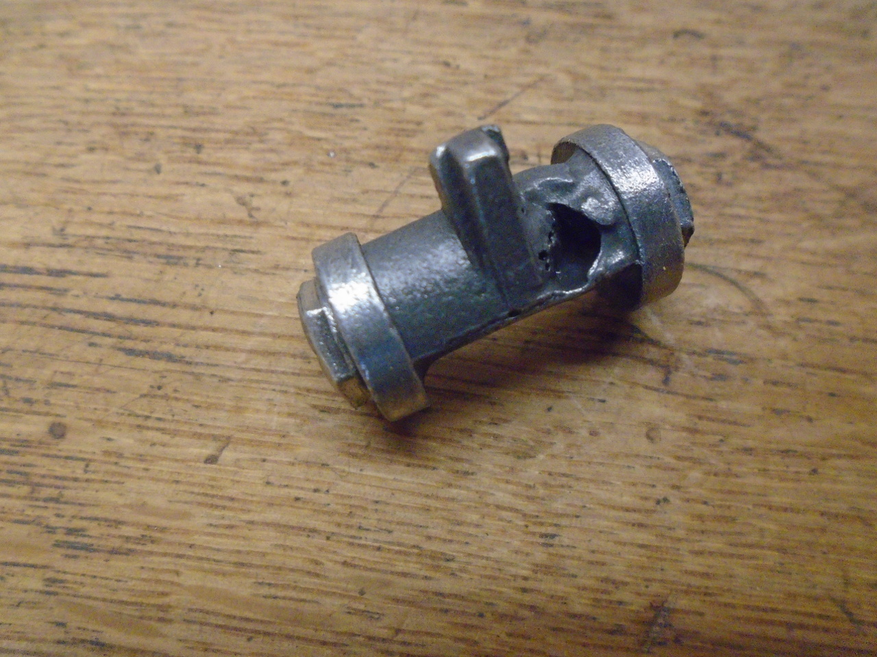
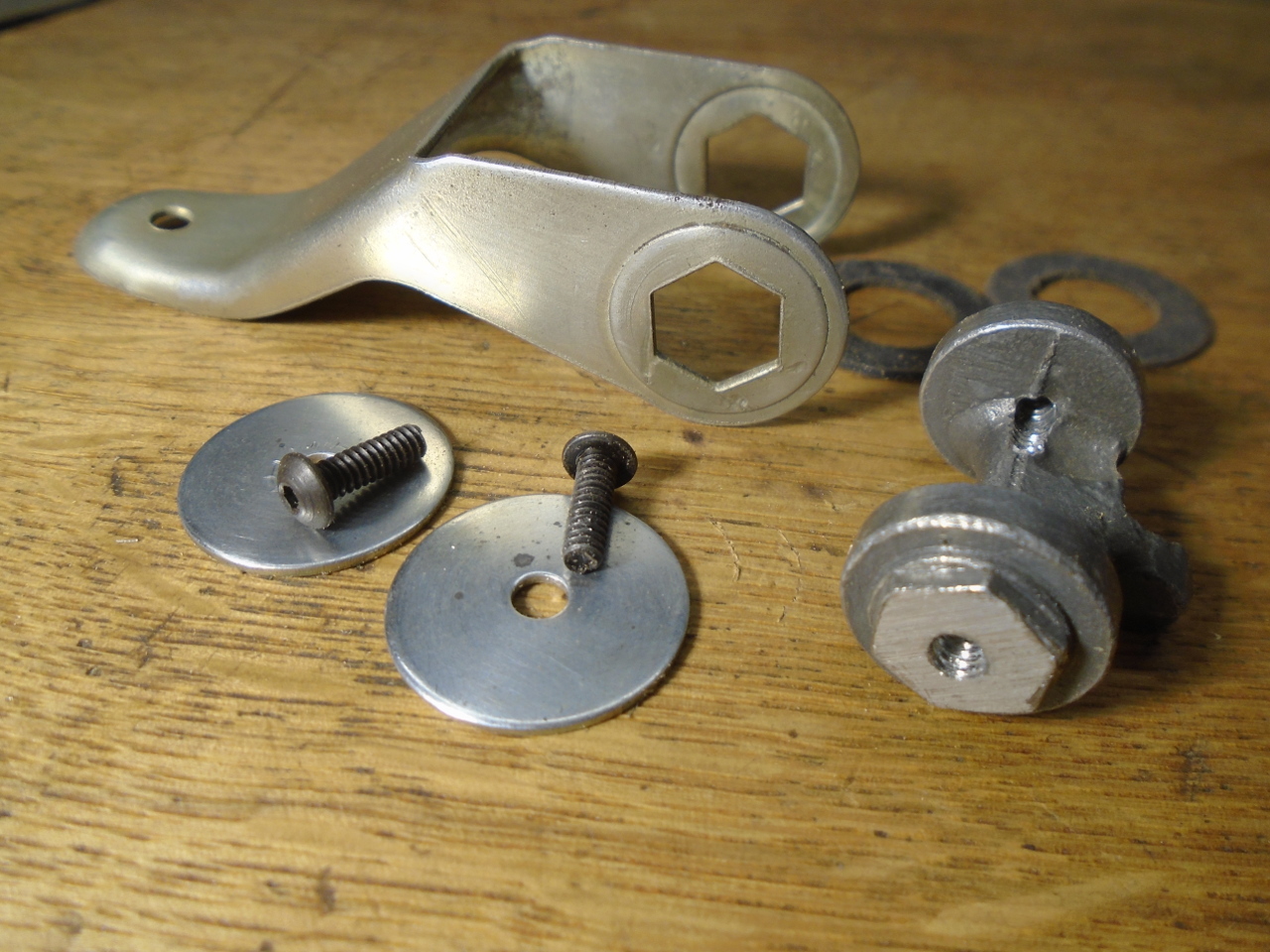
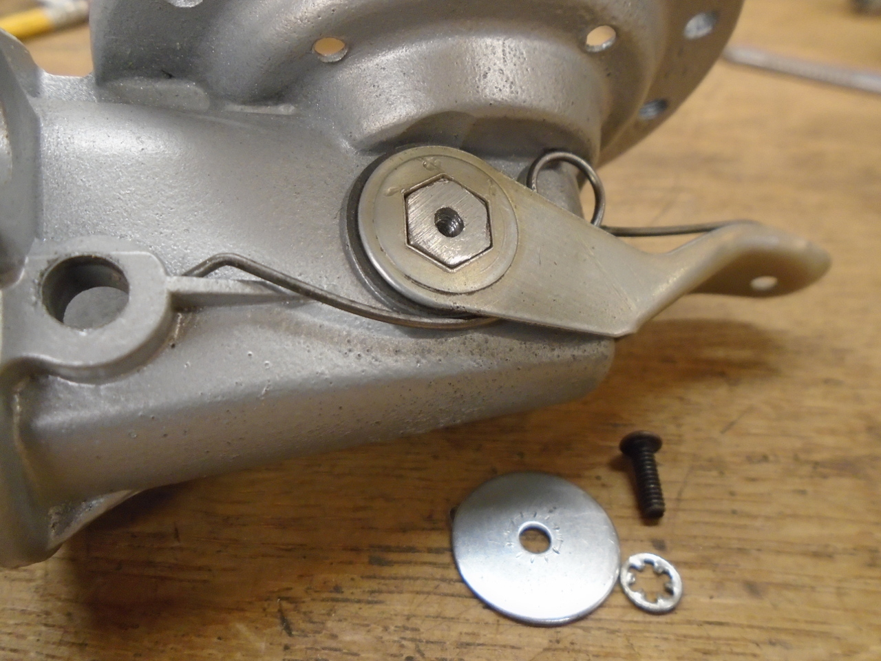
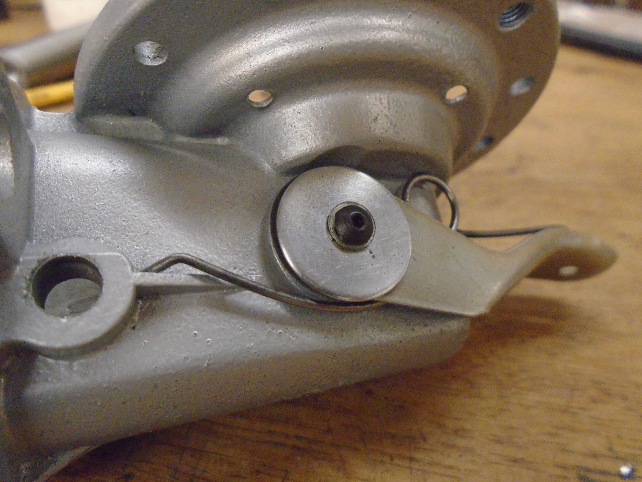
Originally, the primer lever arms were captured onto their spindle
by peening over the hex protrusions on the spindle. There
was probably still enough material to re-peen the lever arms
in place, but I opted to drill and tap the spindle for some small
retaining screws.
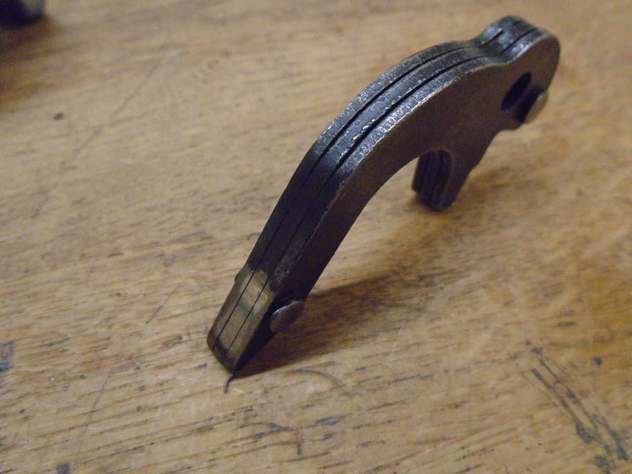
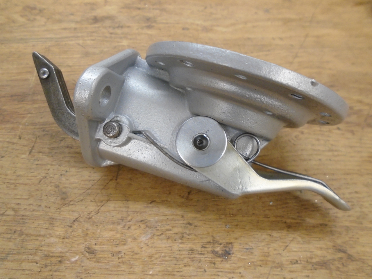
The main actuating lever and associated parts were next.
Most of these parts are hardened steel, which is probably one big
difference between a quality pump, and some of the cheaper
ones. The original lever shows a polished area where it
bears on the cam lobe, but no significant wear.
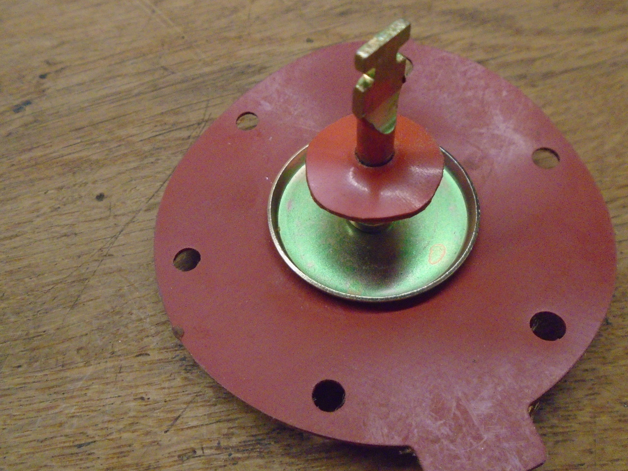
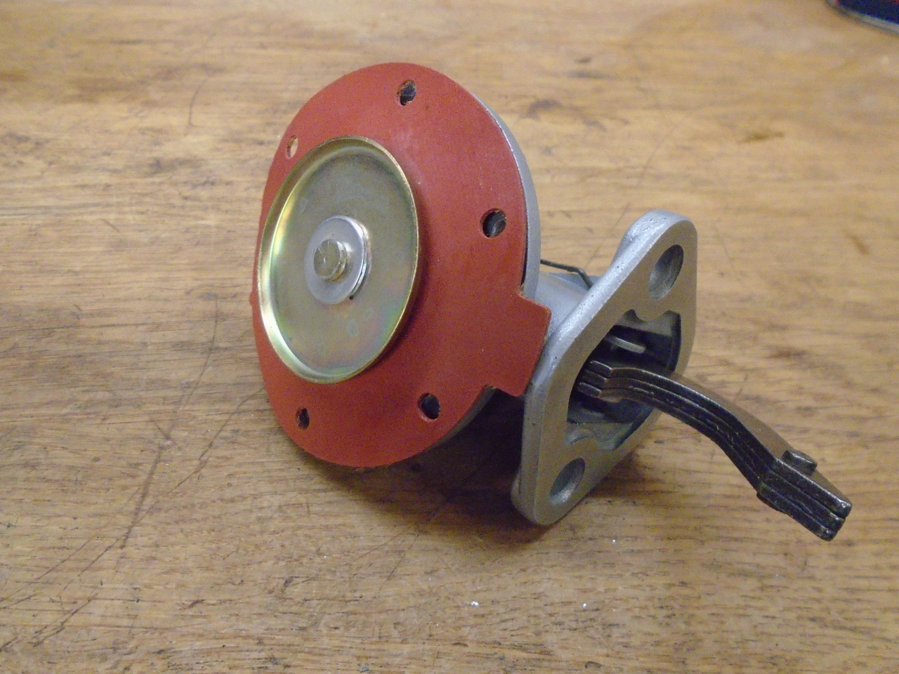
So then it was finally time to join the two halves of the
pump. First, the diaphragm had to be installed. One of
the kits had that black rubber piece in it. It is a seal for
the diaphragm rod to replace the function of the usually perished
original seal. Since I renewed the original seal, I guess I
now have a dual rod seal. An upgrade!
That seal must be for a slightly different pump, though. It
fits fine over the cylindrical protrusion at the center of the
casting, but its periphery doesn't reach down to the floor of the
casting. Since the diaphragm spring seats on the lip of the
seal, it would be better if that lip had some solid support.
Thus the little steel ring shown in the picture. It goes
under the lip of the seal.
Castings reunited. Replated original hardware.
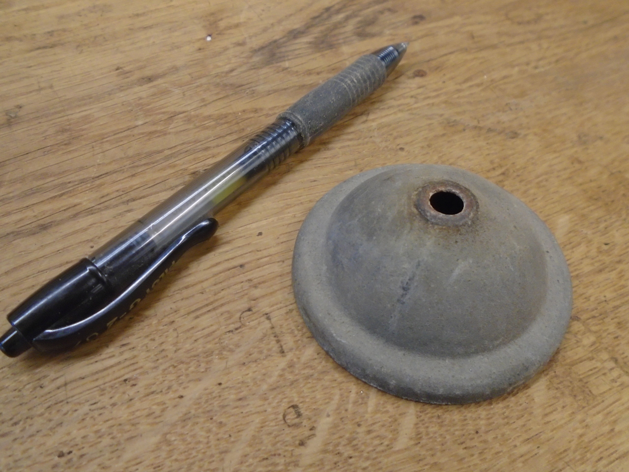
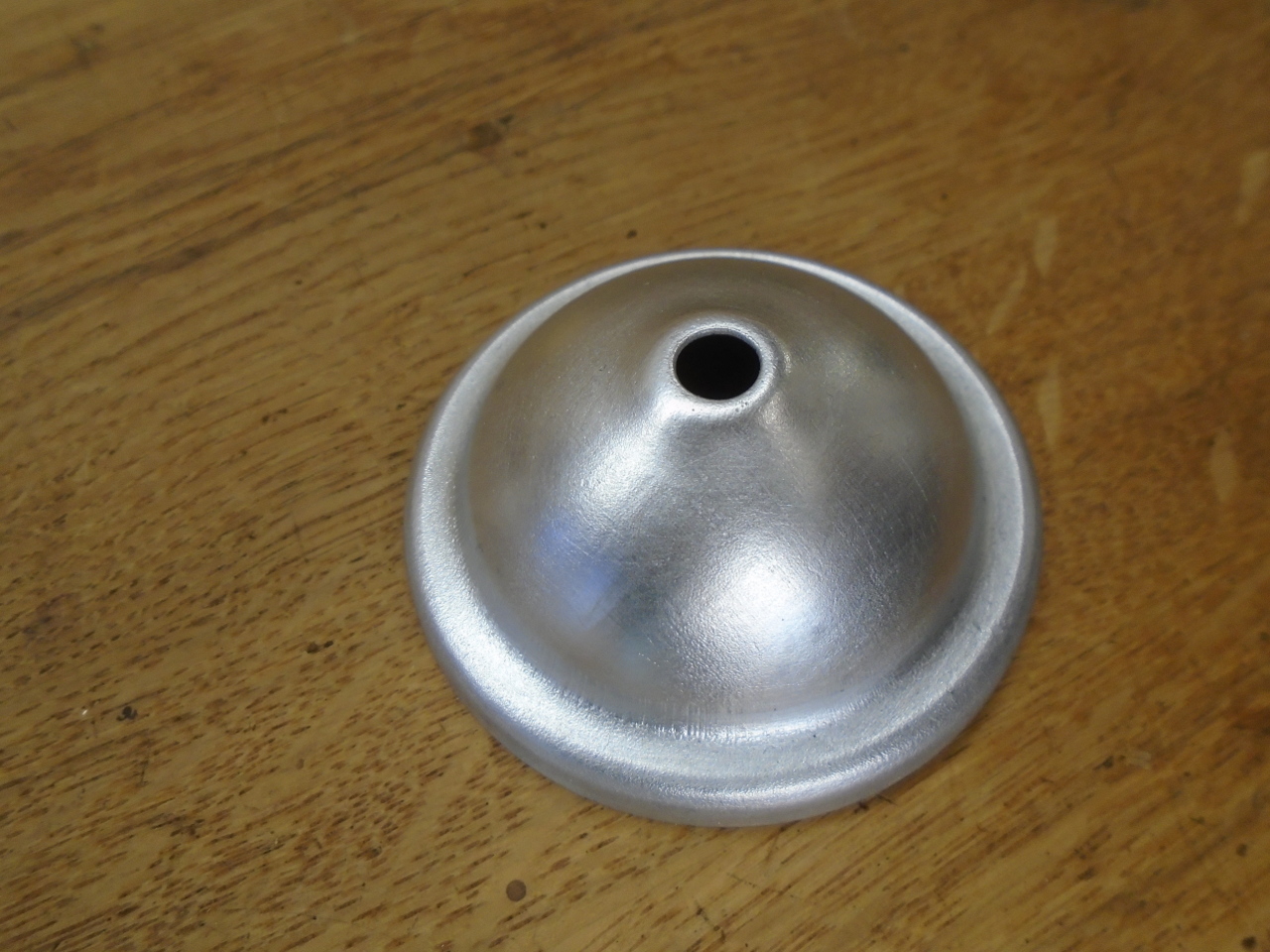
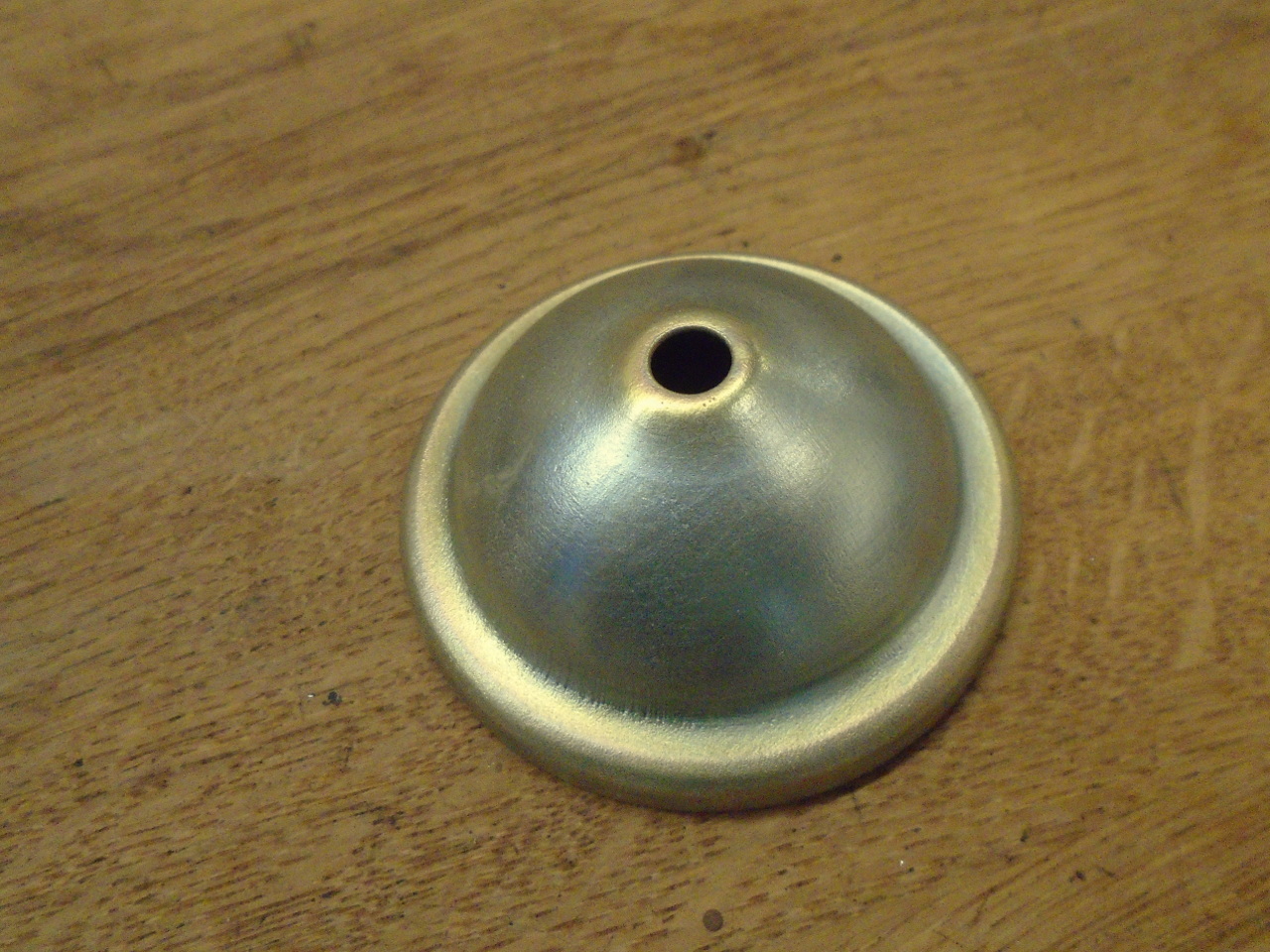
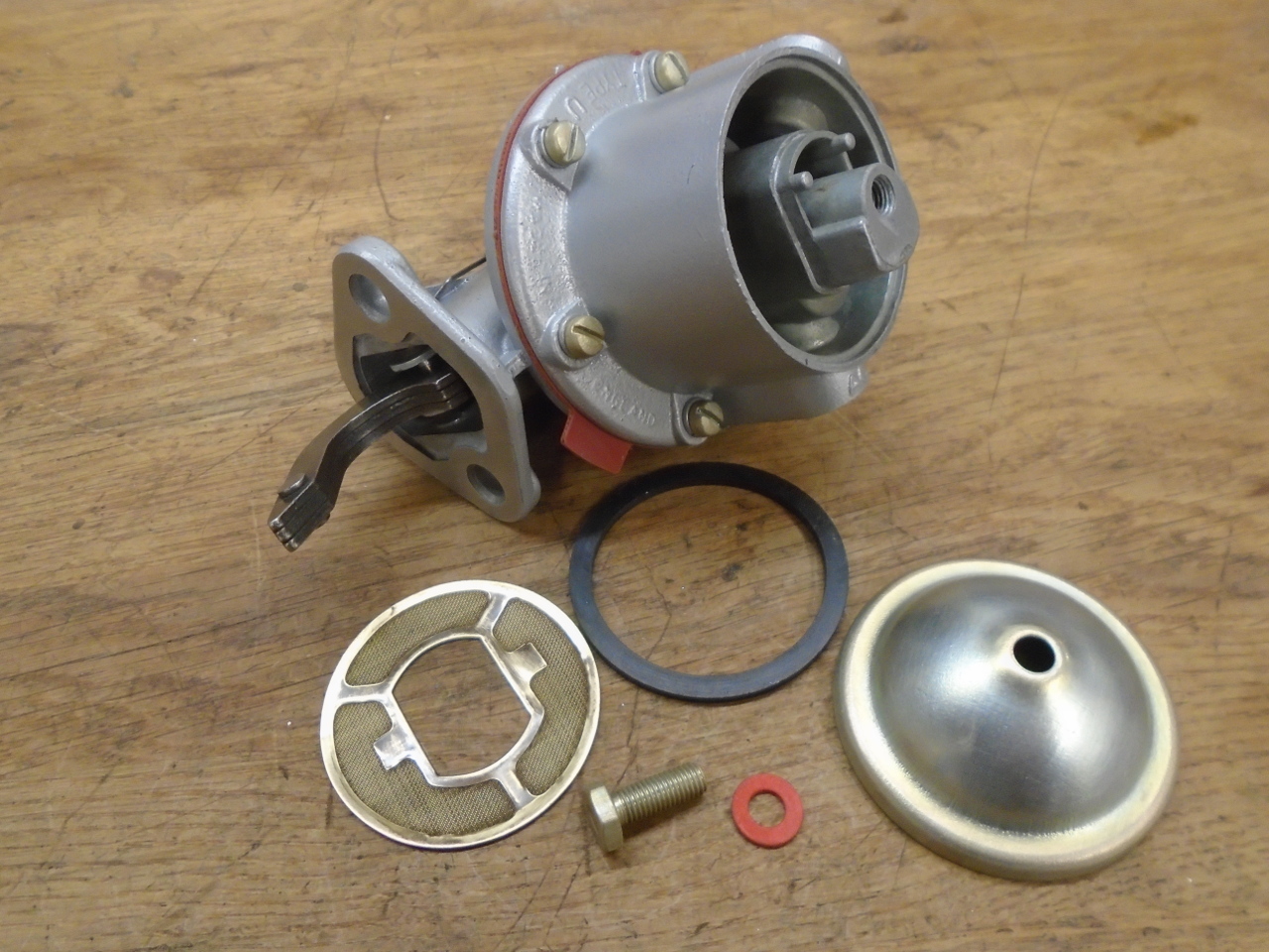
The last of the parts to finish off the top. Replated the
top cap.
On the shelf with this dude.
I've done this job once before, so I sort of knew what I was in
for. I think I may have been able to buy a cheap pump for
what the kits cost, but I believe that I now have a quality pump,
and not a cheap one.
Comments to ed at elhollin1@yahoo.com
To my other GT6
pages