To my other GT6 pages.
February 7, 2024
Crankcase Ventilation
Anyone who has been around old cars knows about the issues related to
blowby. Blowby is the air/fuel mixture and combustion gasses that
leak by the piston rings and into the crankcase. They can cause at
least a couple of problems if not addressed. If the crankcase is
sealed, or nearly so, blowby can build pressure in the crankcase,
causing leaks or even blown gaskets. Further, components of blowby
gas can dissolve in the oil as contaminants.
Early cars avoided problems by simply venting the gasses into the engine
compartment, where they made a mess. Later, a so-called "draft
tube" led crankcase gases down under the engine where moving air would
create a small suction, drawing them out. This practice of course
came under scrutiny as air pollution awareness became a thing in the
60s.
By '69 when this car was built, most cars used some sort of Positive
Crankcase Ventilation (PCV). In these systems, a small negative
pressure was applied to the crankcase, actively sucking out the
gasses. The source of this negative pressure was typically the
induction system, commonly a port in the intake manifold. This of
course means that the blowby gasses would be recycled into the air/fuel
stream to be burned in the engine.
It's not exactly that simple though. Beside needing to keep the
vacuum from getting too high in the crankcase, the flow of crankcase
gasses joining the air/fuel mixture needed to be controlled to be more
consistent so it wouldn't affect AF ratio excessively. Since the
inlet manifold vacuum can vary widely, some sort of regulation was
needed in the passage between the crankcase and inlet manifold.
In this GT6, this regulation was accomplished by the so-called "Smiths
Valve". I was curious about how it worked, so I dug a little.

The Smiths valve is a vacuum regulator, as seen in this drawing from
its 1964 patent. The bottom port goes to the vacuum source
(intake manifold), and the side port goes to the crankcase.

It is actually composed of two valves. The first is a check valve
in the manifold port (18 & 19), which is normally closed, and only
opens when there is sufficient vacuum. It would be closed during
starting and also for any backfire event.
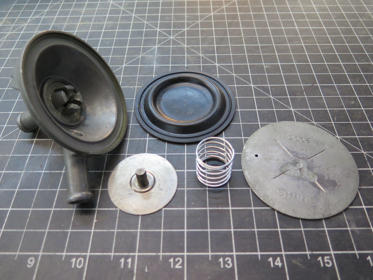
The regulator valve consists of a rubber diaphragm (21) that sees
atmospheric pressure on its topside through an orifice (35) in the top
cover (24). It sees crankcase pressure on its bottom side.
With the engine running, vacuum at the bottom port will pull gasses from
the crankcase, and lower the pressure on the bottom side of the
diaphragm. This pulls the diaphragm down, which lowers the plunger
(32) into its bore, thus reducing the flow, and also reducing the
vacuum at the crankcase port. This has the effect of regulating
the vacuum that the crankcase sees.
According to the patent, the device regulates vacuum to between one and five inches of water (inH2O).
This confused me, since this is a very low vacuum, only about 0.04 to
0.2 psi. I seemed to be of the opinion that normal crankcase
vacuum with a working PCV valve would be a few psi or so. I
thought maybe the units were a misprint and should have been inches of
mercury (inHg). One to five inHg would be about 0.5 to 2.5 psi.
As a sanity check, I did a little experiment. My 74 TR6 with a
similar engine has no PCV valve, but uses carburetors that have a
constant vacuum port coming from the mixing chamber. (The "CD" in the
Stromburg model numbers stands for "constant depression", same as
constant vacuum.) I temporarily tapped into that port on one of
the carbs and hooked it to a manometer, and took a drive.

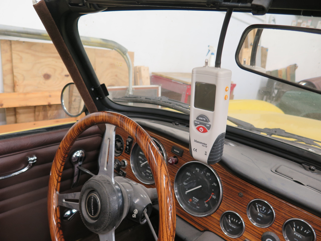
The result? At idle or cruising, vacuum at the carb port is around
3.5 inH2O. Step on it, and the vacuum rises until the air piston
catches up, as expected, but rarely went above 15 inH20 or so.
So the patent was right, and I was wrong.
The question then became, do I want to install the original Smiths valve, or is there a better alternative?
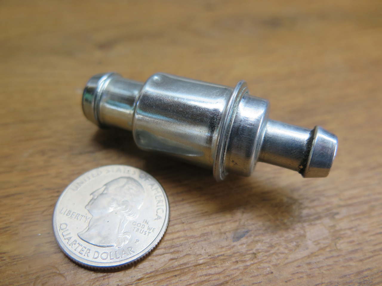
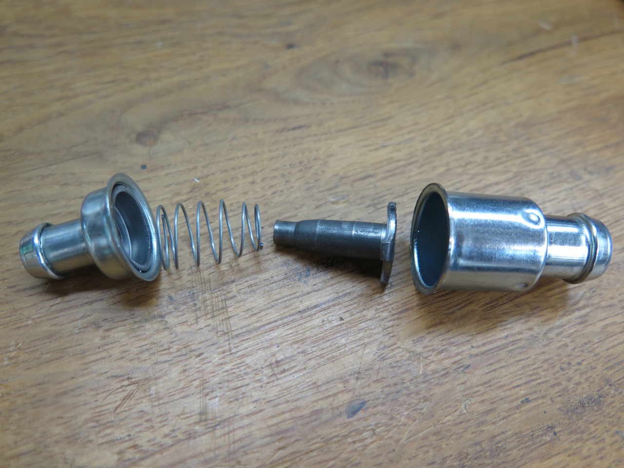
Many cars have used a much simpler and cheaper PCV valve. I bought a few
to look at. They are all similar inside. A shuttle rides
inside a cylindrical space. A light spring holds it to one
end. Apply a vacuum at the other end, and the flow moves the
shuttle against the spring. The shuttle has a tapered nose that
moves into an orifice, restricting the flow. The broad head on the
shuttle also served as the check valve.
I'm not that kind of Engineer, so I'm a little beyond the edge of my
competency here, but it seems that since the simpler PVC has no
reference to atmospheric pressure, and the shuttle responds strictly to
flow, it would be properly called a flow regulator, while the Smiths
valve, with its diaphragm that moves in response to pressure would be
more of a (negative) pressure regulator.
In the end, since Triumph deemed it worthwhile to use a more complex, more expensive valve, then I would too.
The question then became: does my valve work properly?
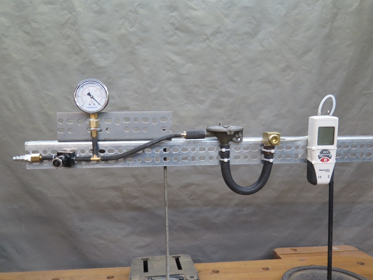
More science ensued. I set up a simple test bench. A vacuum
pump connected to an adjustable vacuum regulator, which fed vacuum to
the Smiths valve. The other side of the valve was connected to an
orifice to simulate the restricted flow from a crankcase, and to a
vacuum gauge. By varying the input vacuum to the valve and
recording the output vacuum, I could see if it regulates.
I could see some regulation, but it seemed erratic. There was some
indication that I wasn't getting enough flow through the valve. I
measured the flow. With my pump, regulator, and all the hosery, I
could manage almost one CFM of flow. Regulators typically have to
have a certain minimum amount of flow to work properly. Was that
enough? I didn't know.
Research ensued. What is the typical volume of blowby in an engine of this size?
Anecdotal evidence, guesses, and conjecture were all over the place, but
I came across a couple of rules of thumb that seemed to be from
knowledgeable sources. One said a typical engine in reasonably
good condition would produce, on average, about one CFM of blowby for
every 500 cc of displacement. Another rule said that dividing the
engine horsepower by 50 would give an approximate prediction of blowby
in CFM. These two predictors give 4 and 2 CFM as the expected
blowby volume. I considered these estimates to be in reasonable agreement.
So, since the Smiths valve was probably designed to work with at least 2
CFM or so of flow, my test setup was marginal. I was able to
boost flow somewhat by shortening hoses and moving to larger sizes, and
finally saw some good regulation in the 2-4 inH20 range.
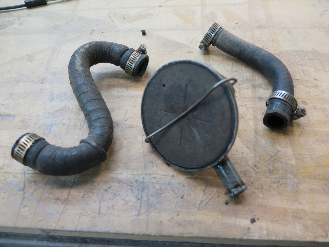
At this point, I had a working valve that I wanted to use. But
there was one remaining problem: The way the factory mounted the
valve is butt ugly. It looks like a cheap, clumsy afterthought
tacked onto an otherwise decent looking engine. The silly "S" hose
looks awkward and inelegant.

The task was to connect these two ports to each other with the valve inline, and not have it look like a baboon designed it.

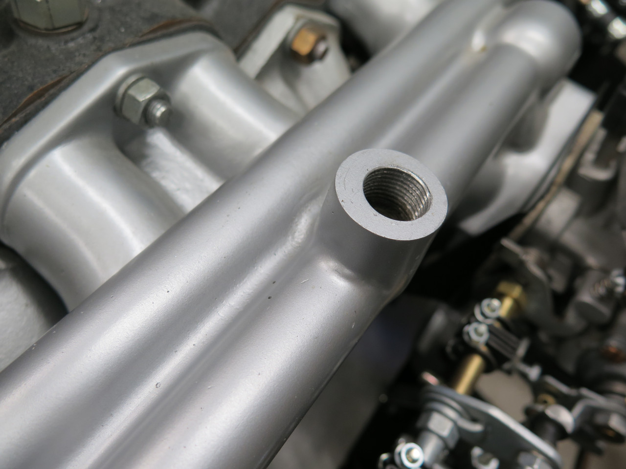
There is one important part of the ventilation system that is not
apparent here. Behind the valve cover port is some mesh "filter"
material designed to intercept and coalesce oil mist and return it to
the sump. This was not included with the aftermarket valve cover.
This was my first attempt to replace the S hose with something more
sightly. A banjo bolt would connect this 3D printed gizmo to the
manifold, and the valve would go in the other hole, held with a grommet.
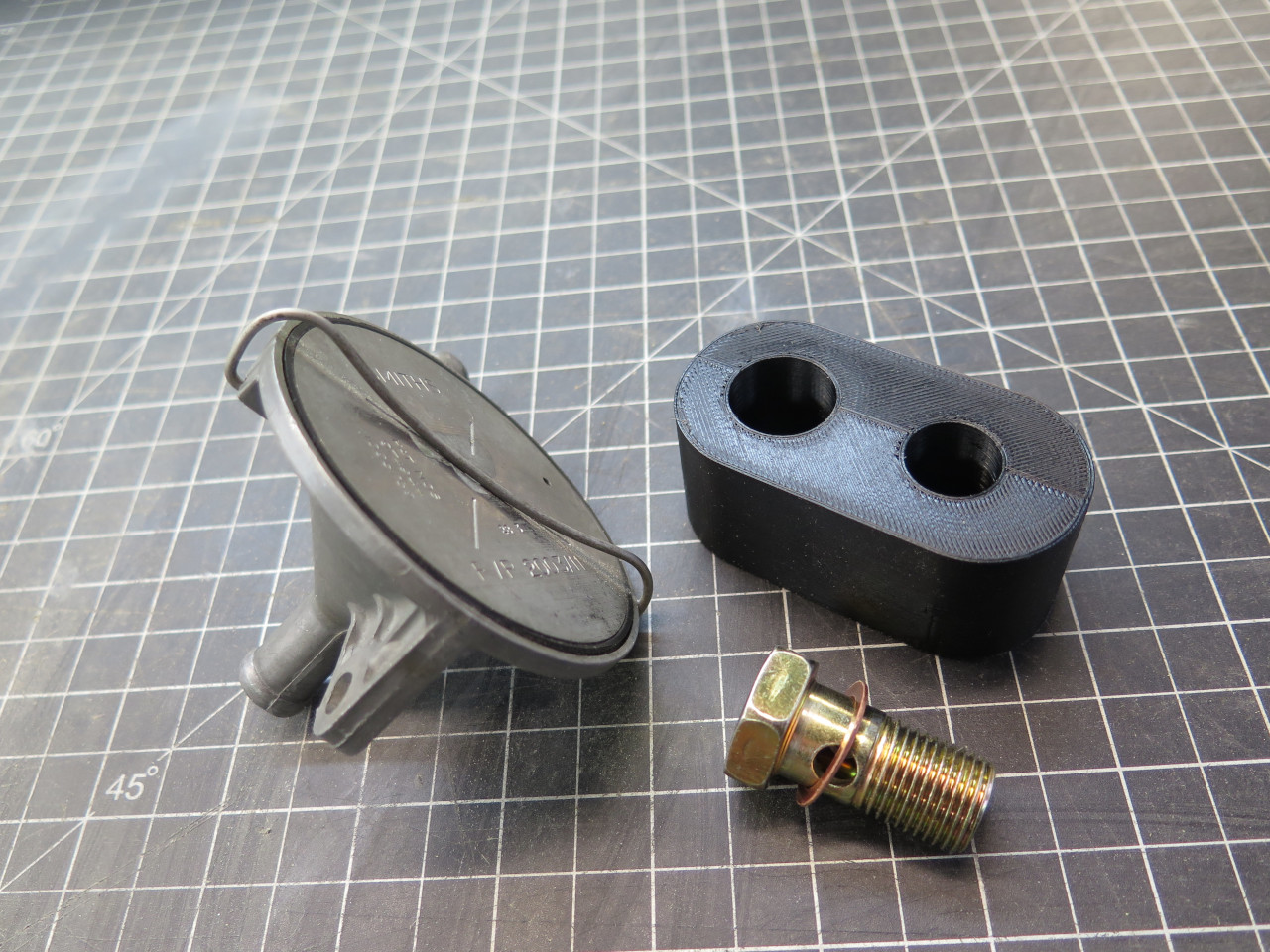

This looked good, but the mounting bracket of the valve fouled the banjo bolt.
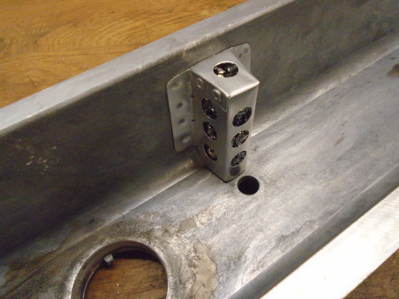
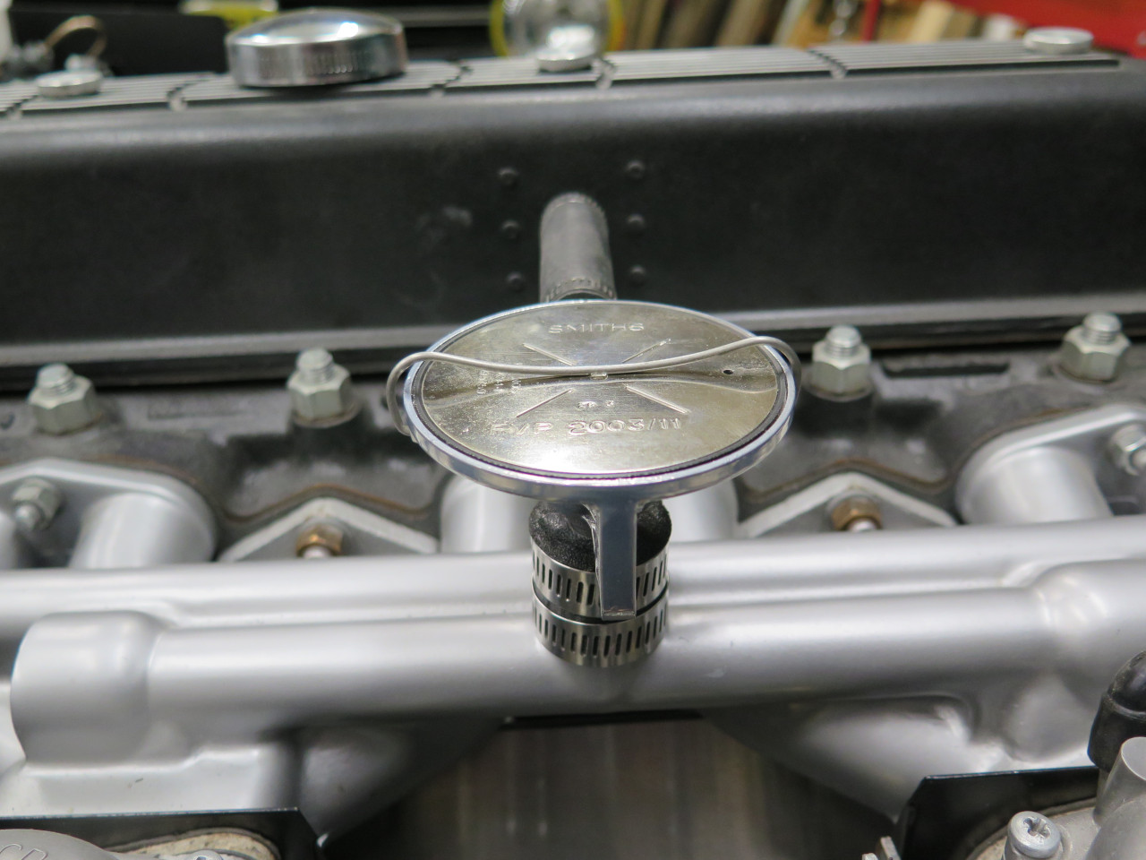
What I finally landed on was this much simpler adapter. It's 3D
printed in TPU, a soft, rubbery polyurethane. Instead of threading
into the manifold port, it clamps to the cylindrical boss that holds
the port.
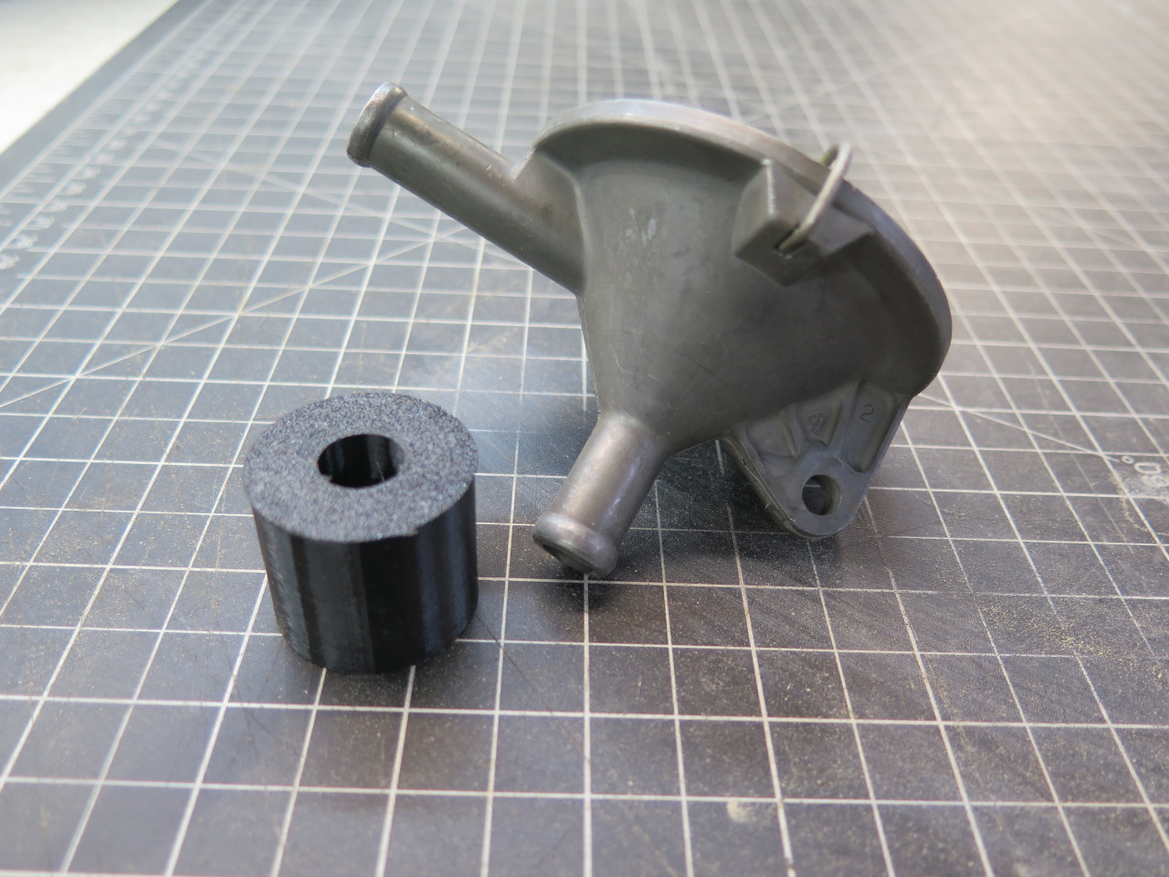
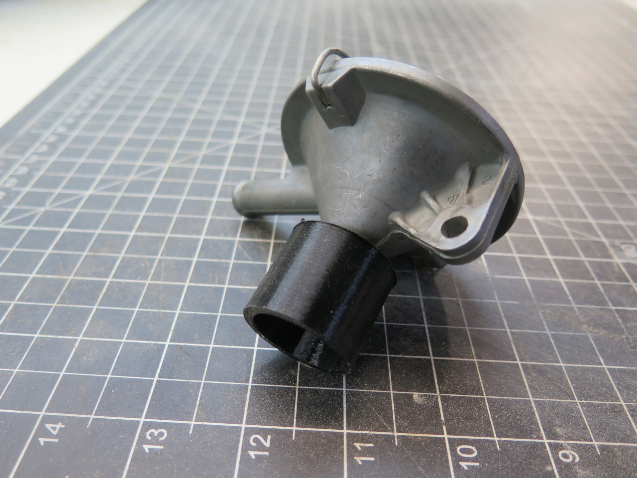

The fit is pretty good, even without hose clamps.

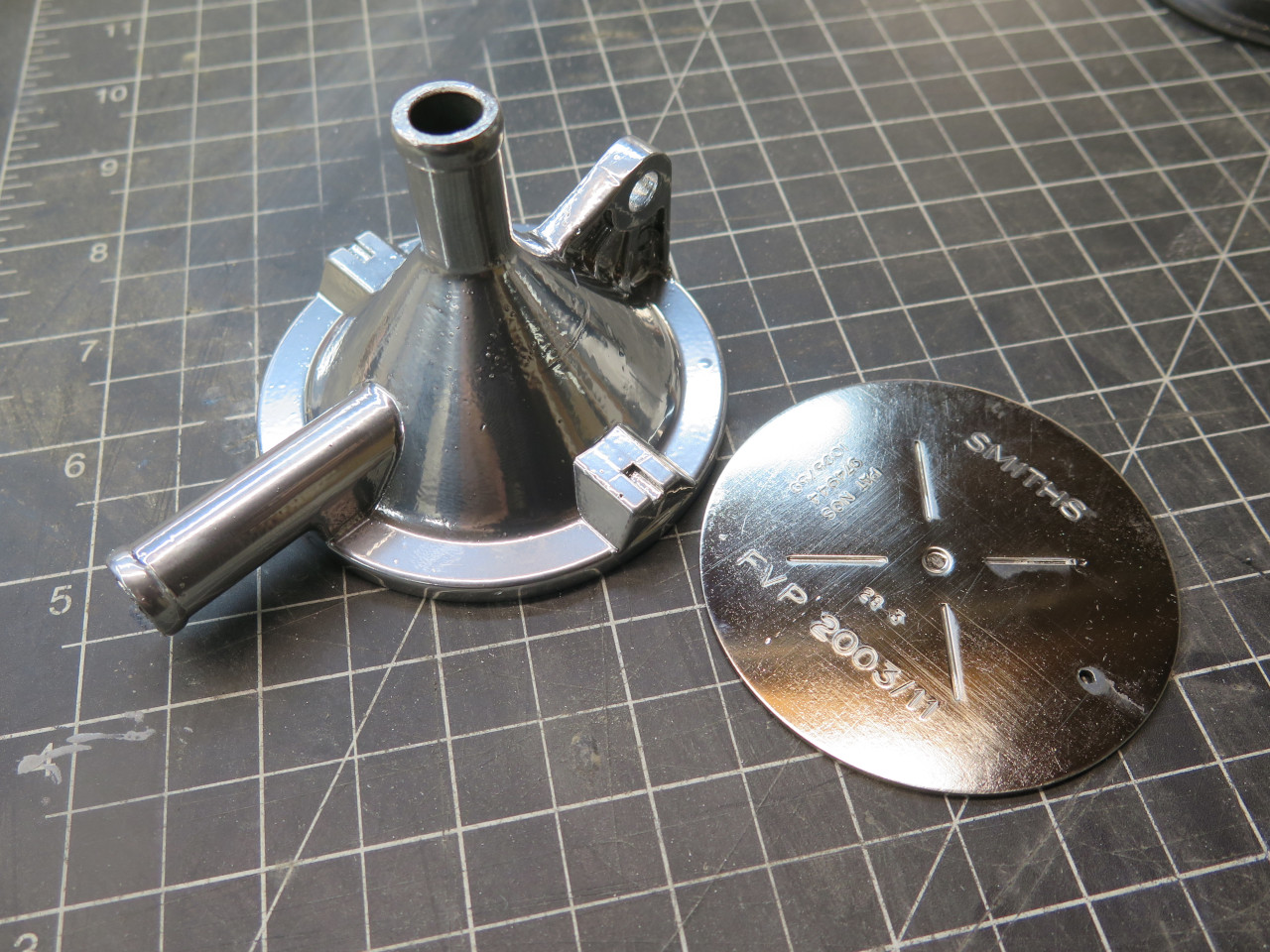
This looked like it would work, and not look too bad. Since the
valve was in such a prominent place in the engine bay, it seemed
worthwhile to doll it up a bit. Silvery powder coat on the body,
and nickle plate the top cover.
The valve installation looks about as clean as it can, I think.

This was supposed to be a quick, simple little task, but it sort of
morphed into a science fair project. Kind of fun, though.
Cost for parts and materials was essentially zero.
Comments to Ed at elhollin1@yahoo.com
To my other GT6 pages.