To my other GT6 pages.
October 13, 2023
Battery Stuff
At this point in the overall project, the wiring harness installs were
complete, except for connections related to the battery, like the
starter and the alternator. I thought it was time to buy a
battery.
The battery for this car was missing when I started the project, so I
didn't have much to go by. As for physical size, some research
revealed that the original battery may have been a "Group 24", which is
listed as nominally 10.3" x 6.8" footprint, and 8.9" tall. There
are other battery size groups with similar or smaller dimensions that
would also likely work fine. I ended up buying a "Group 34R"
battery, which has the same footprint, but is an inch more squat than
the Group 24. The "R" suffix designates that the positive and
negative terminals are swapped compared to normal. A contributing
factor to my choice is that this is the same battery size that I used in
my TR6.
This is an "AGM" (Absorbed Glass Mat) battery. These batteries
have a lot of great features that make them worth the premium price, but
the main reason I favor them is that they are essentially sealed.
They can allegedly even be installed on their sides or ends (but not
upside down, apparently). I like AGM batteries for the same reason
I like DOT5 brake fluid--less potential for damage from leaking.

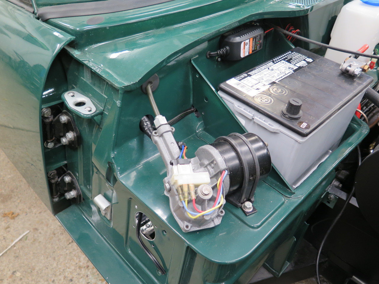
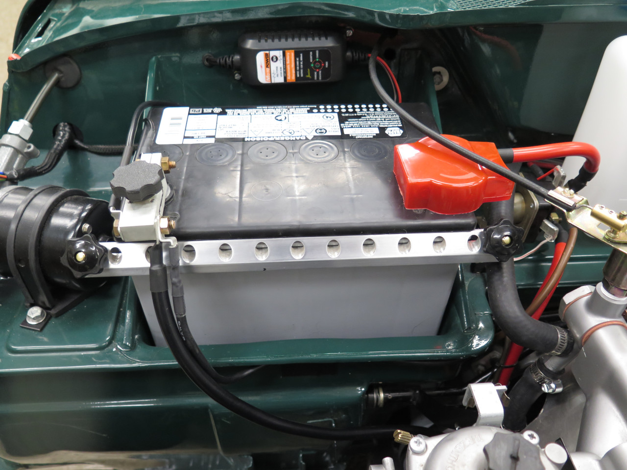
The battery is a snug fit in the battery box. There is no room for
a plastic battery tray, but if it lives up to its billing, a tray
shouldn't be necessary.
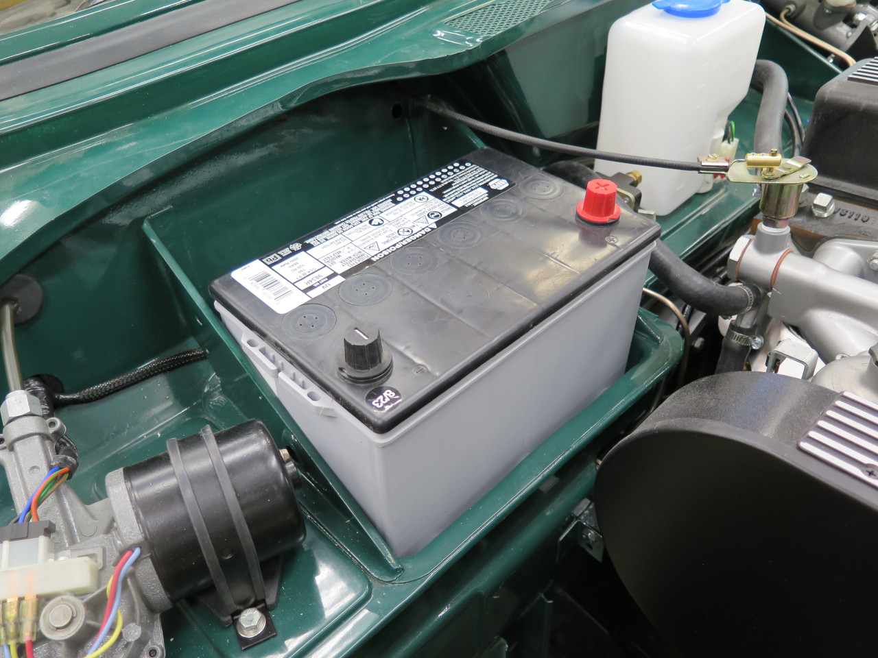
There was apparently a battery hold-down arrangement originally, but I
found no trace of it in my nearly empty boxes of parts. I suppose
they can be bought, but it seemed like a nice little shop project for a
rainy afternoon or two. I could surmise how the hold-down
worked: A bar across the top front of the battery is pulled back
and down by an adjustable strut at each end. The struts hook into
holes in the gusset plates at each end of the battery box.
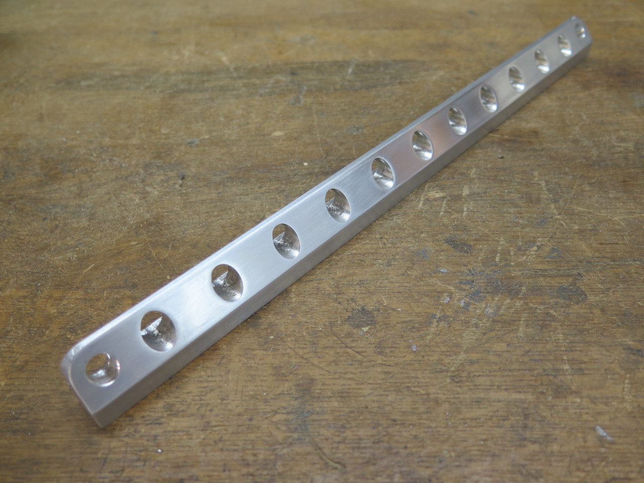
For the bar, I started with a piece of aluminum.

The bar was shaped to make it better looking, and a groove on the
backside fits over a protruding lip that runs along the front of the
battery case. The racing holes add at least 5 HP.
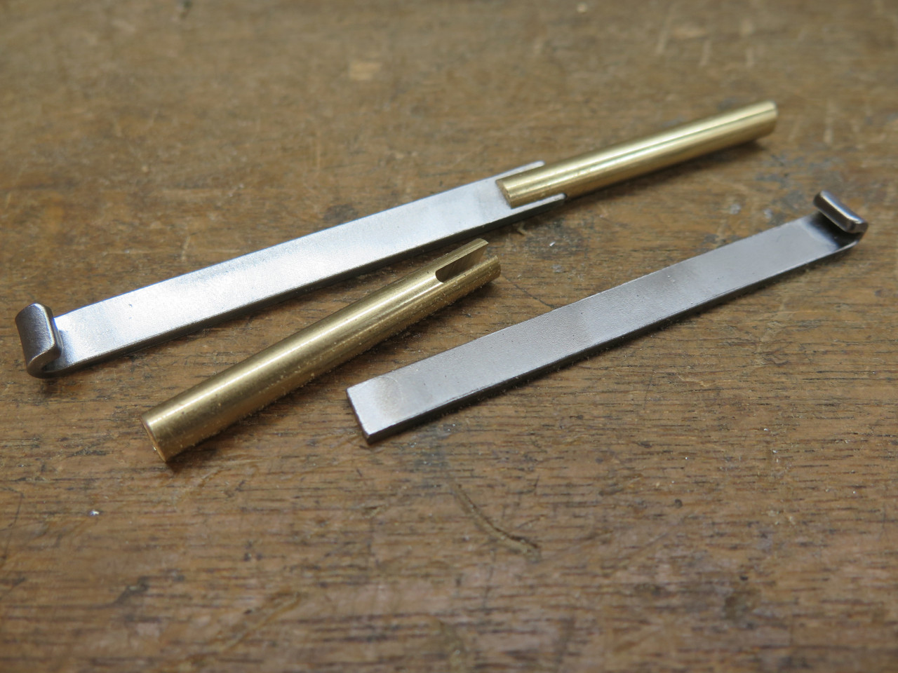
The struts are just pieces of flat steel with a hook at one end.
Those were silver brazed to short brass rods threaded at one end.
The steel part was powder coated, and some plastic knobs added.
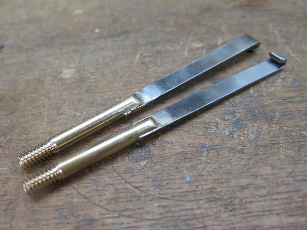
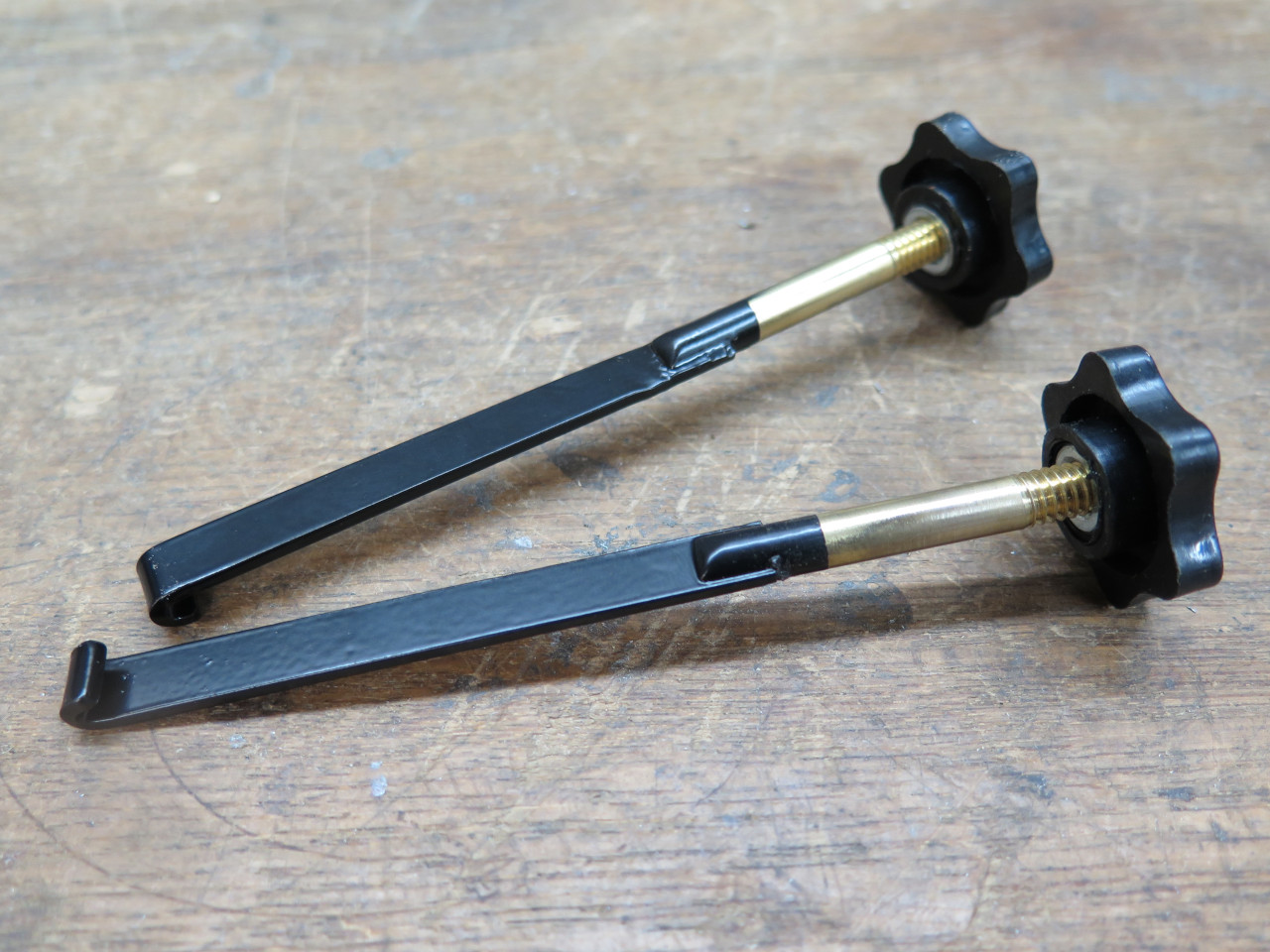
Seems to hold the battery pretty well.

Like my TR6, this car will be mostly laid up during the winter, and I'll
use a so-called "battery tender" to keep the battery in good
condition. These devices are pretty smart, and by monitoring
battery voltage, they can go into various modes to give the battery what
it needs. Tenders can be left connected indefinitely, but I
usually just connect it for a day every few weeks, mainly because I
didn't like the clutter of the tender and wires.
"Wouldn't it be nice," I thought to myself, "if the tender could be
permanently mounted somewhere out of sight, yet be easily powered
up?" The answer hit me immediately: Dedicate a tender to the
car. Mount it in the car, near the battery, and provide an easy
way to connect AC to it. A project was created then and there.
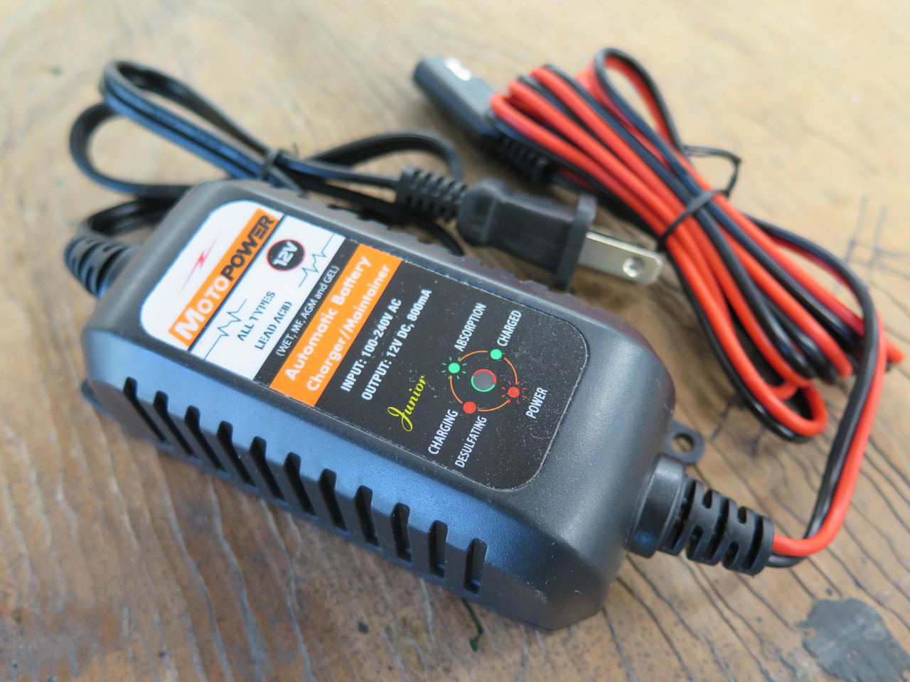
I didn't need a big or powerful tender. This is about the smallest
I found. It's maximum charging current is less than one amp, but
this should be fine over long terms. It is mounted to the firewall
with a couple of rivnuts.
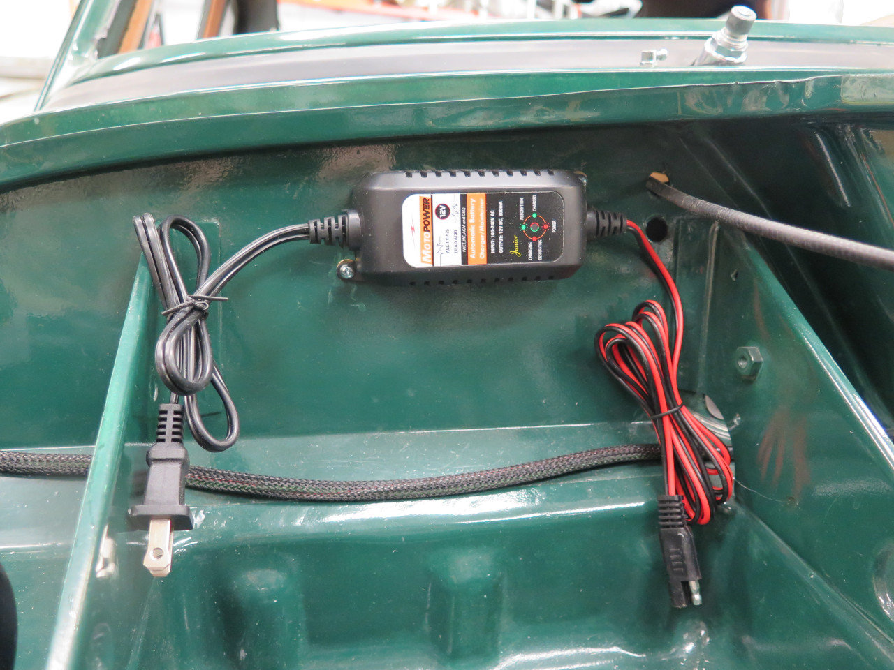
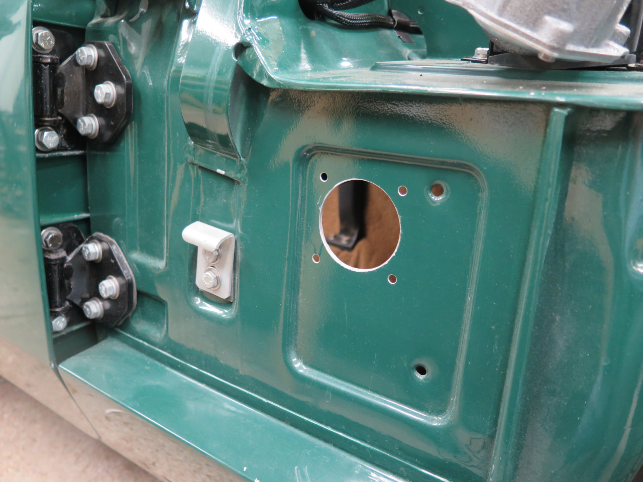
For the AC power, I envisioned a simple plug and play. I
considered several places for the connection, but finally chose this A
post side panel. It's pretty close to the tender, has good access,
and plenty of room to run a cord even with the bonnet closed.
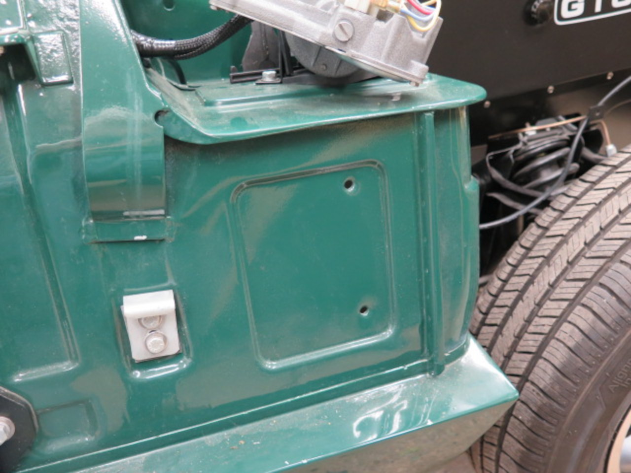
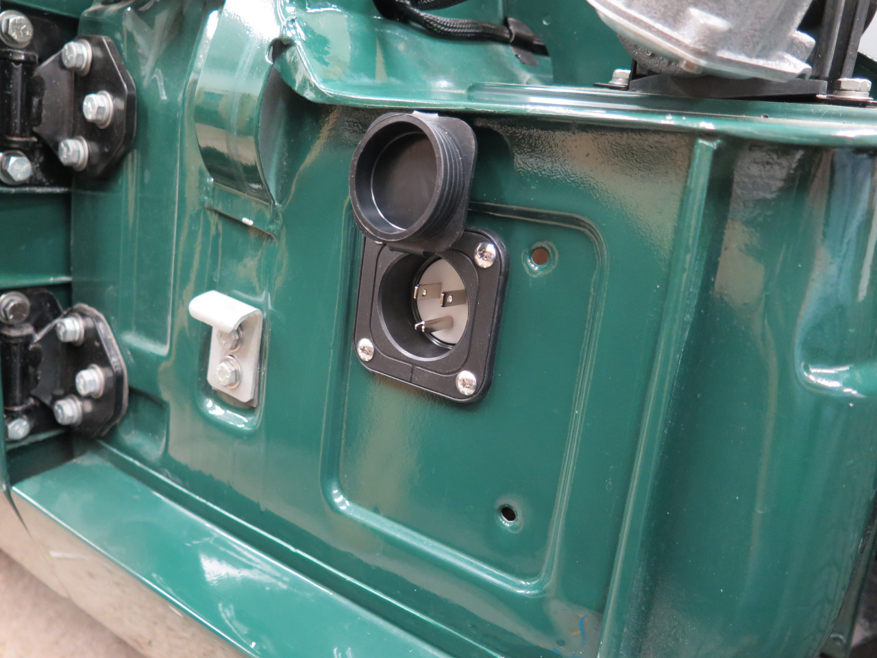
This panel mount AC connector is apparently made for connecting shore
power to boats. My application actually seems a little similar.

As a rule, I don't really like making mods to this car that aren't
easily reversible. This is bending the rule a little. The AC
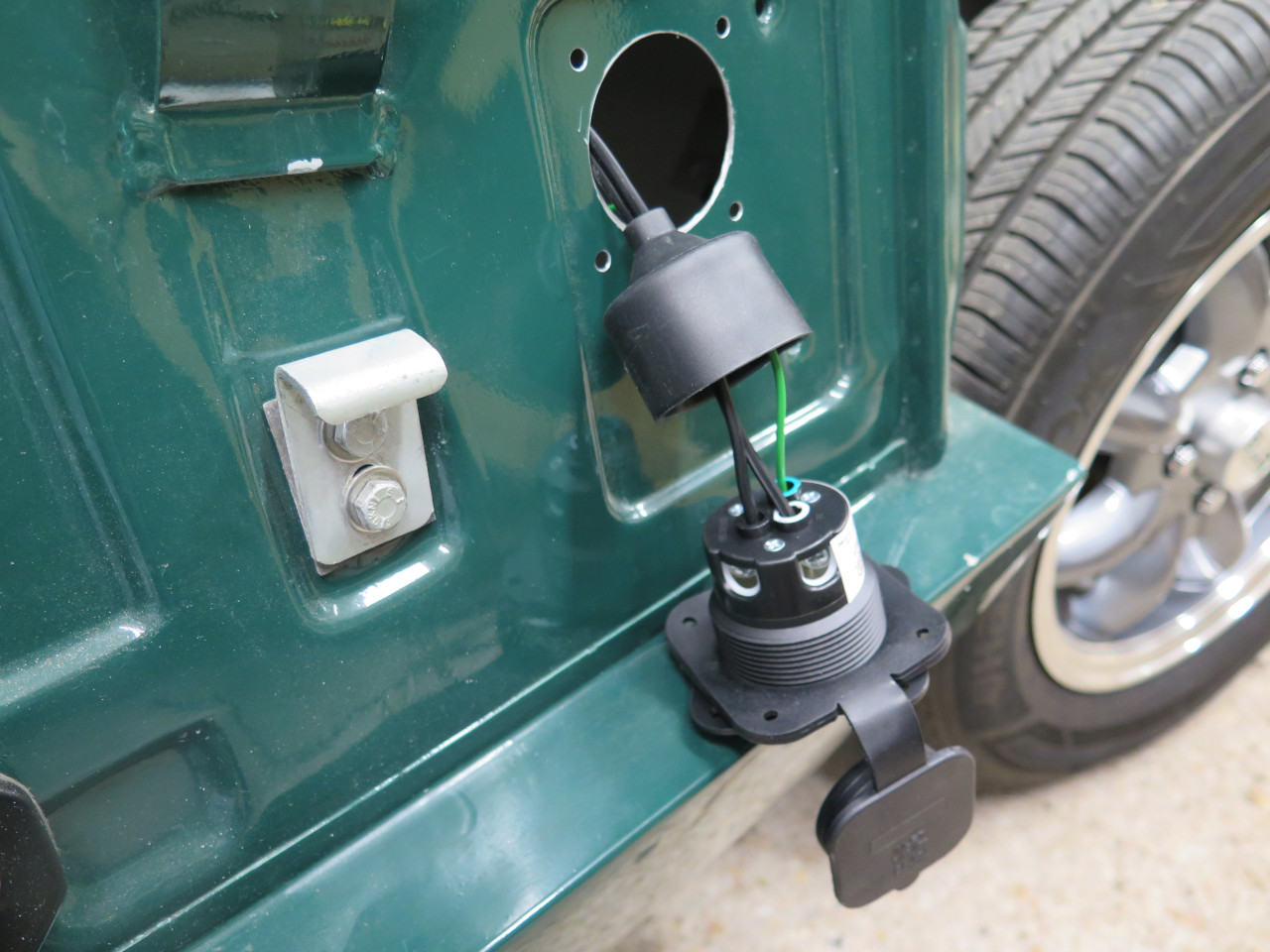
cord for the tender is pretty short, but barely made it to the hole.
The tender is in a plastic case with no exposed metal parts, so it
doesn't need a three-prong plug. However, the car itself does have
exposed metal parts, and bringing AC power into it requires that it be
connected to a safety ground. The green pigtail will connect the
car body to the house electrical ground.

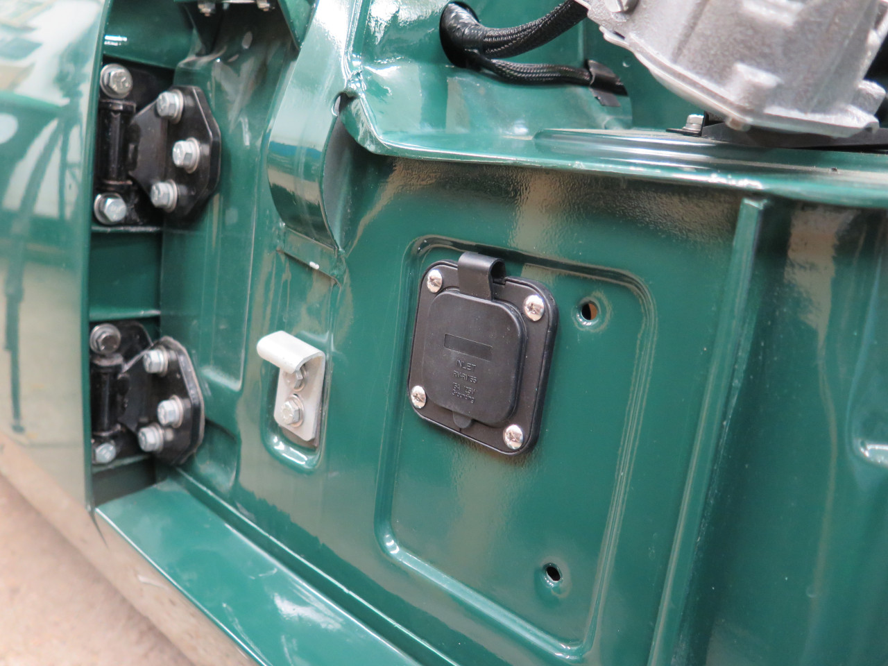
The connector is installed pretty high up in the passenger's footwell, so there shouldn't be much chance of damage.

Almost looks like it belongs there.
Next up was the remainder of the alternator wiring. The circuit
for the dash indicator light, which also supplies the alternator's
bootstrap field current, had already been included in the front cable
harness, but the main battery charging circuit still needed doing.
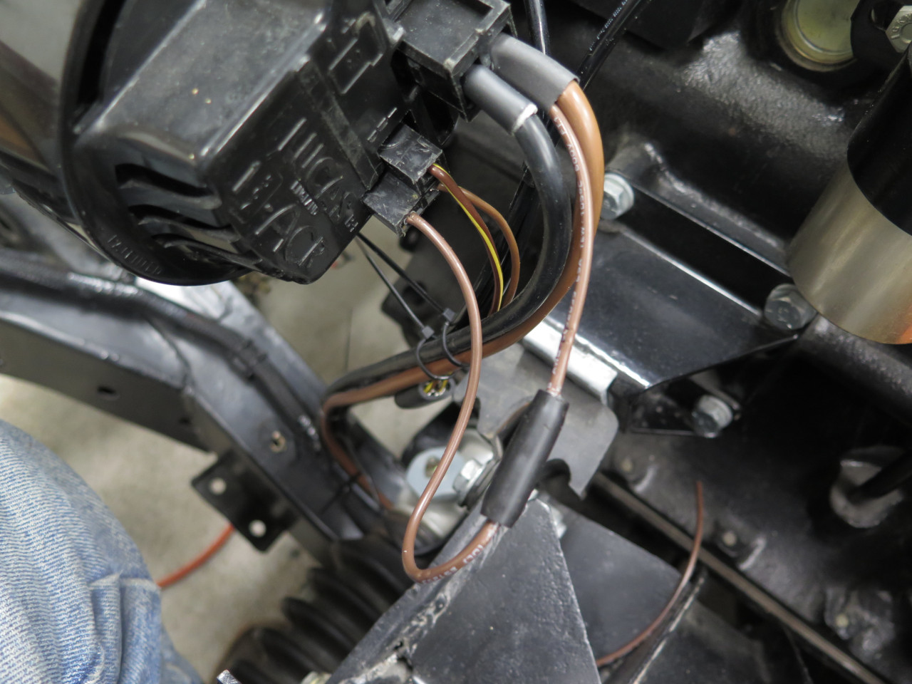
The 15ACR alternator in this car is a little different from many other
British units in that it has an explicit negative output terminal that
doesn't appear to be electrically tied directly to the case. Maybe
this was to facilitate it being used in positive ground cars, but I
don't know. The original wiring just had a short pigtail on the
negative side tied to one of the mounting bolts. In keeping with
my design goal to eliminate the car itself as a ground return wherever
possible, if they give me a negative terminal, I'm going to use it.
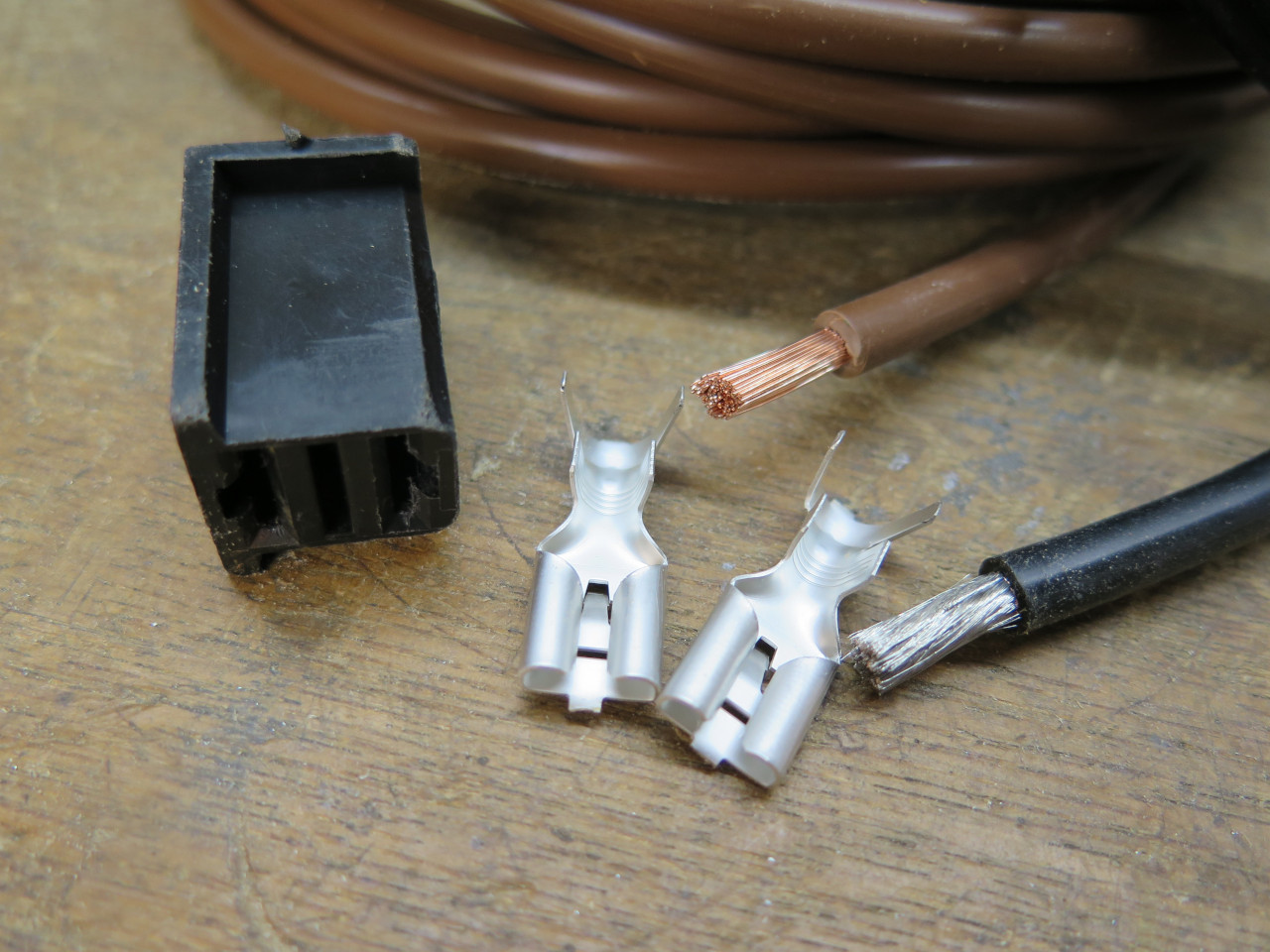
The original connector housing was still seemed serviceable, but the wire and terminals had to be replaced.
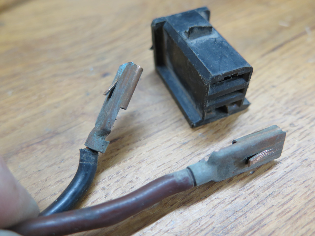
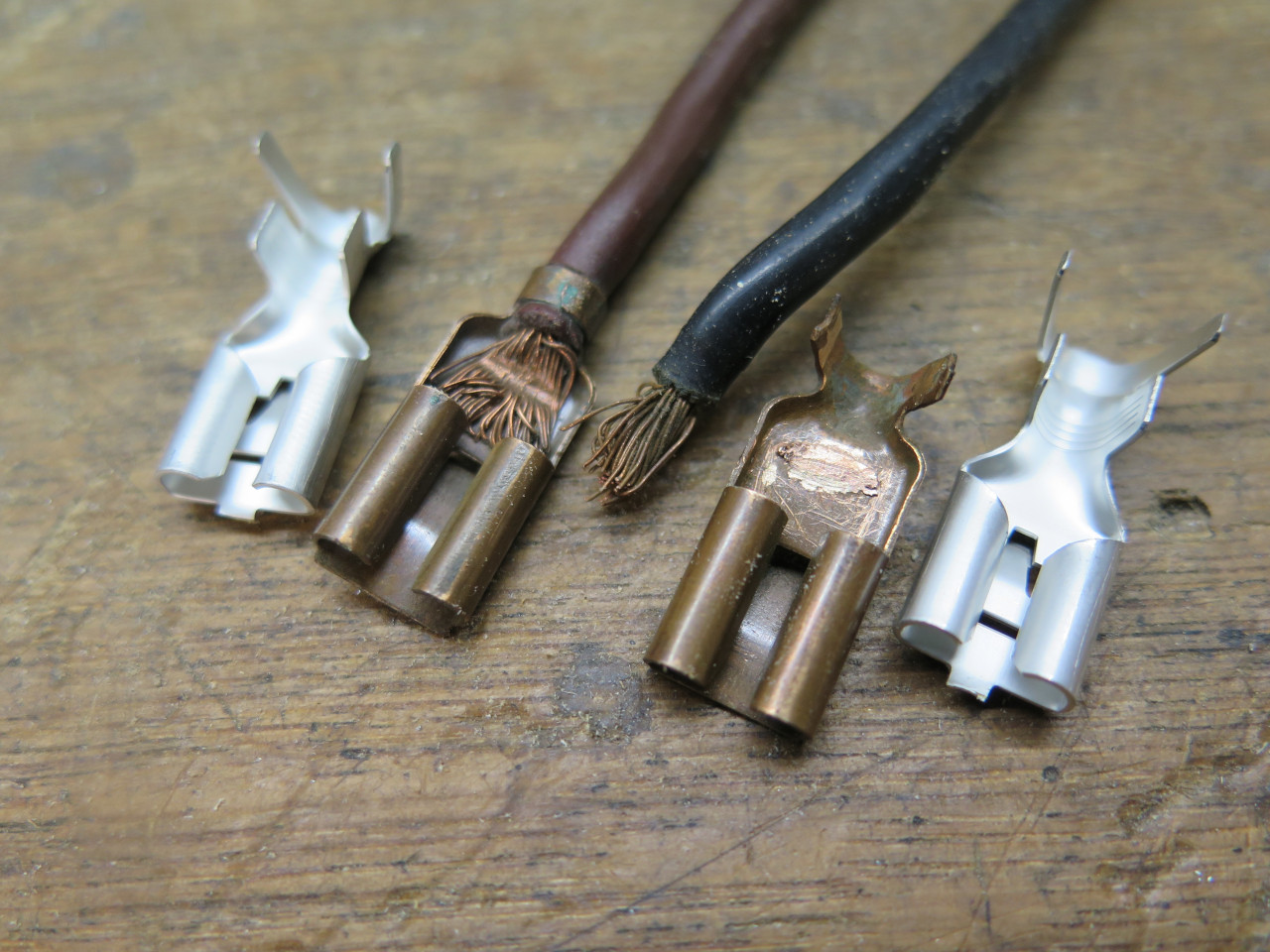
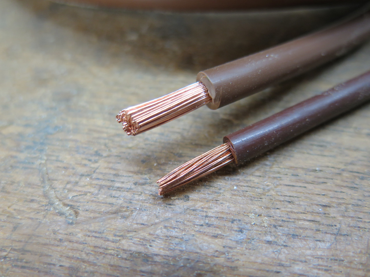
The original wire for the charge circuit was British "65 strand", which
is a little smaller than US AWG 10. This seemed a bit marginal to
me for a device that is rated at around 30 amps. So to rectify
this and to allow for a possible upgrade to a higher output alternator, I
opted to increase the wire size to AWG 8.
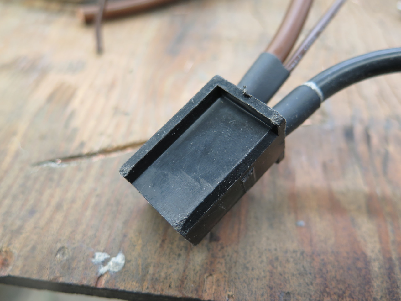
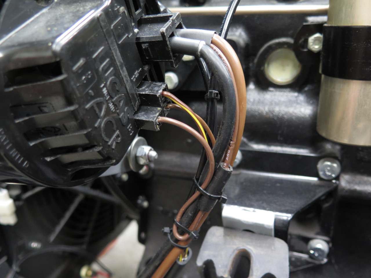
Slipped the new terminals and wires into the original housing. The
smaller brown wire provides a measurement point for the alternator's
output voltage. Alternators get feedback about system voltage
through a sense wire. It allows the alternator to adjust its
output so that the system voltage stays at the target value. There
are two main ways that the sense wire can be connected. In "battery
sense", the sense wire is connected directly to, or very close to, the
battery positive terminal. In "machine sense", the sense wire is
connected to the positive output terminal of the alternator (the
alternator is the "machine"). Now in practice, those two points
are connected directly together with a wire that carries the
alternator's output current, and will only differ by whatever voltage
drop occurs in that wire.

I opted to use machine sense, mainly because it is one less wire to run,
and one less connection to the battery. The increased size of the
alternator output wires should keep the voltage drop to a minimum.
The sense terminal is on the smaller connector, so it just connects to
the positive output terminal. The butt connector is so I can
separate the two alternator connectors if necessary.
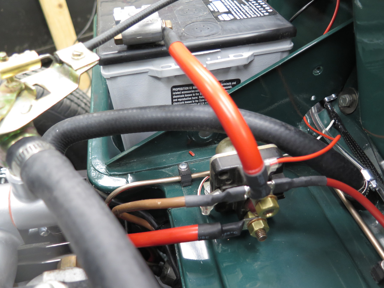
So eventually, all of these circuits have to come to the battery.
On the positive side, a logical place to bring the wires together is the
top post of the start solenoid. Four wires need to attach that
post: the large cable from the battery positive terminal, the 8
gauge wire from the alternator, an 8 gauge wire that feeds the power
module and the rest of the car, and the wire from the battery
tender. I really wanted to use quick connects for the three
smaller attachments to make troubleshooting and maintenance
easier.
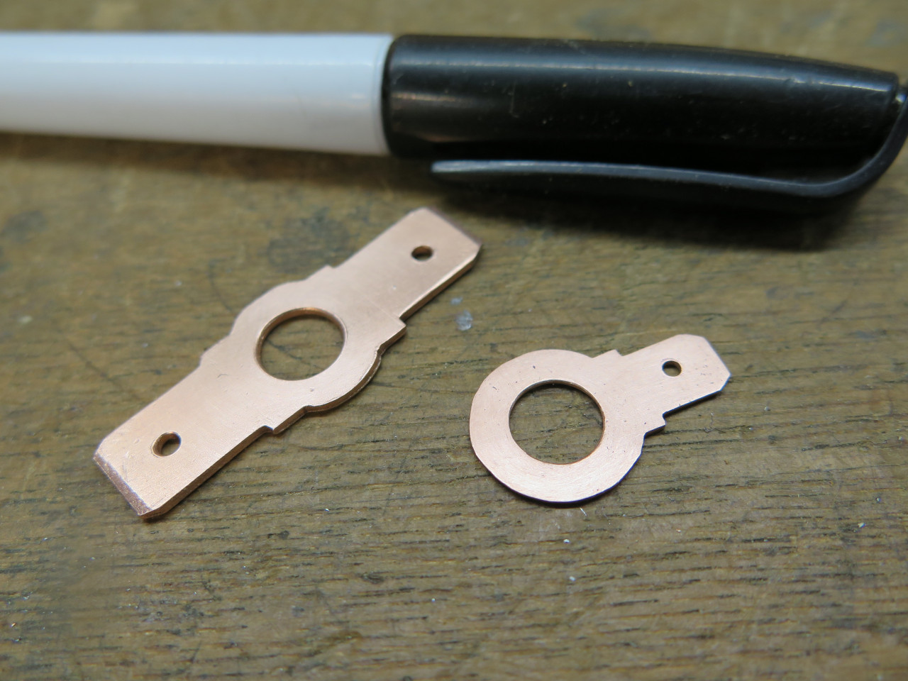
These little copper tabs go on the solenoid post and provide attachment
points. they were made separately and soldered together because
the 1/4" and the 3/8" tabs have to be different thicknesses.

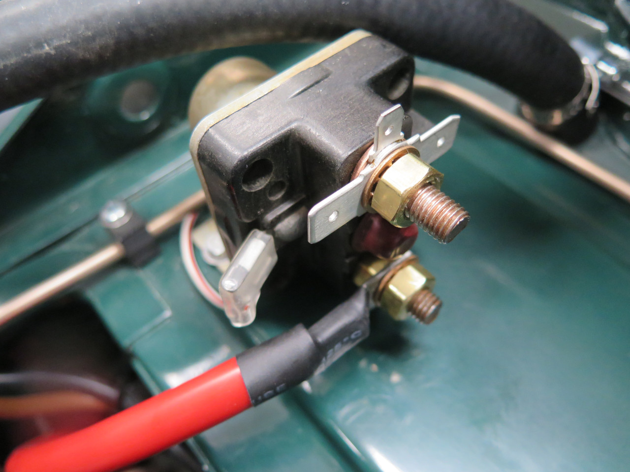
Everything connected. Brown wire goes to alternator. Big red
wires go to battery and to starter. Medium red wire goes to the
Power Module for all loads on the car (except starter). Small red
wire is from the battery tender.
All the circuits also have to come together on the negative side too, of
course, but it's a little more complicated there. First, there
isn't a convenient tie point other than the battery terminal
itself. Second, I wanted to install a battery shutoff. I
looked at a few battery shutoff devices, and at a few battery terminal
connectors that provided multiple attachment points for wires, but I
didn't really find much that would do both. I faced the same
challenge on my TR6, and the solution I found there seems to work well,
so I decided to copy it for the GT.
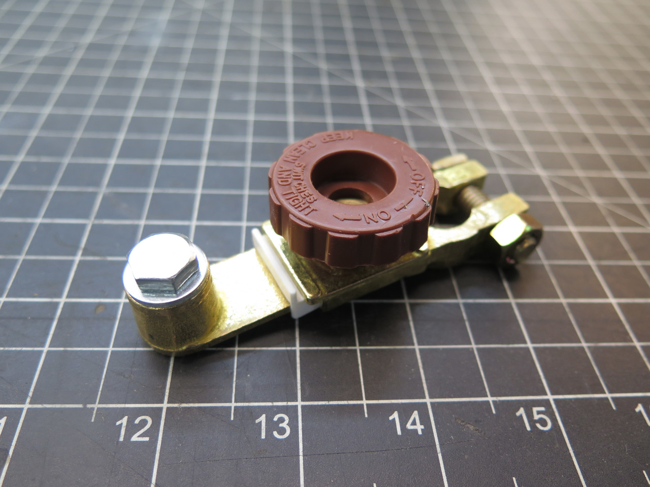
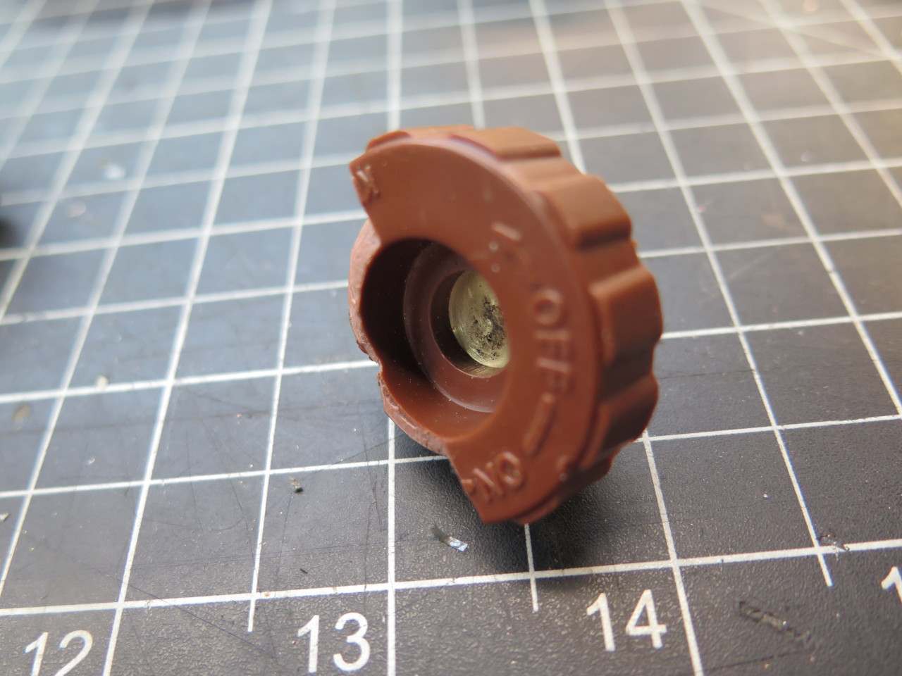
I took a lesson from some of the ubiquitous shutoff devices that connect
directly to the battery. I liked the concept, but didn't like a
few things: The color suggests that the body might be made of
brass. it's not. It's just pot metal. If the knob is
removed completely, the assembly can fall apart. It didn't have an
easy way to provide multiple wire attachment points. I actually
bought one of these gizmos, thinking I could use the knob in my own
design.

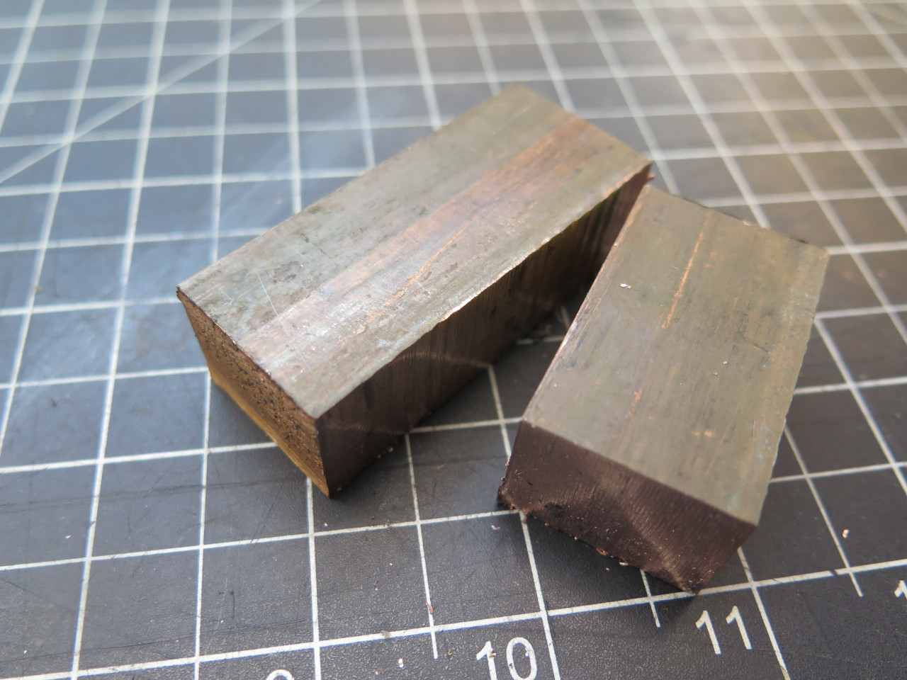
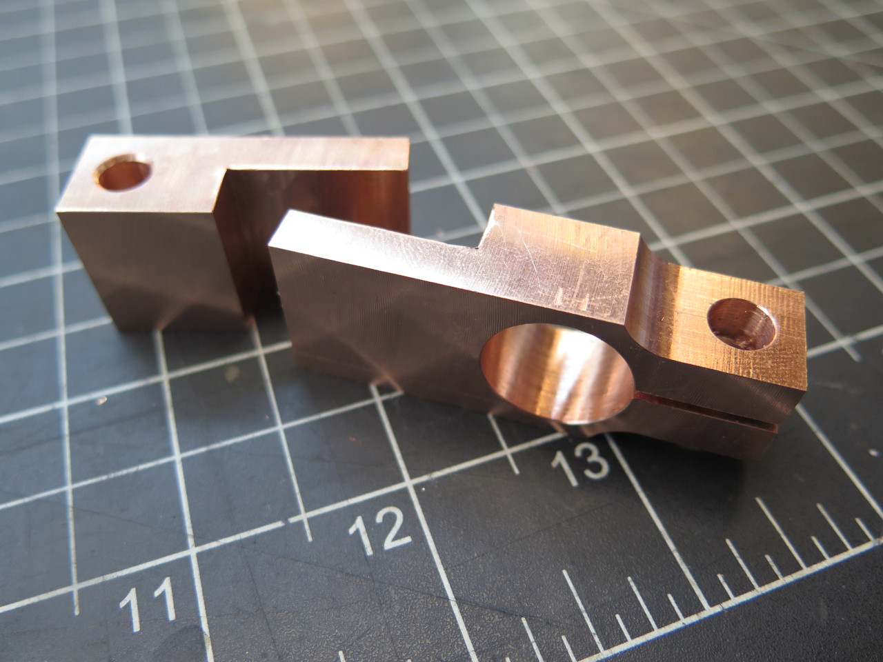
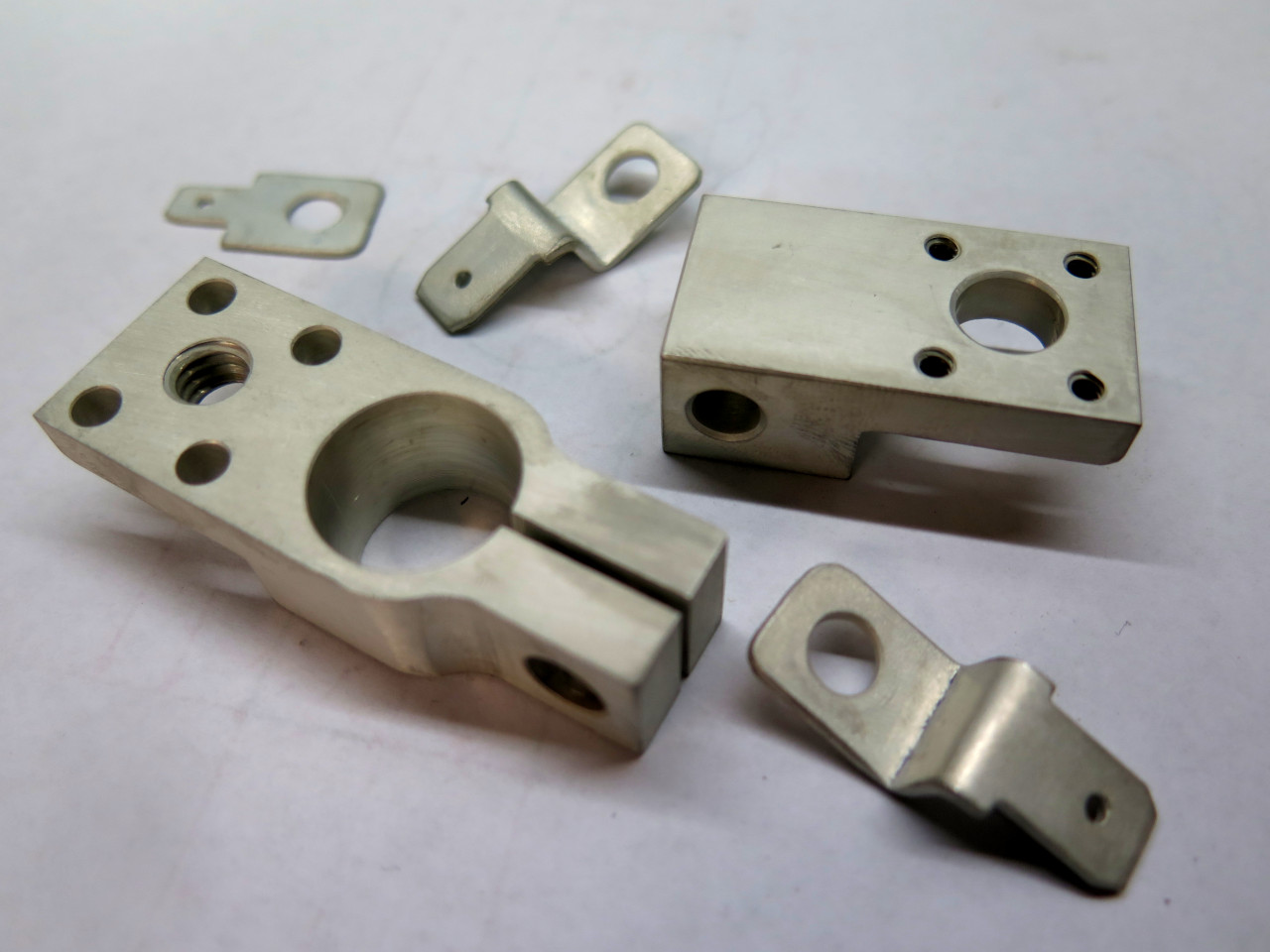
Starting point was a couple of small hunks of copper. Some pleasant hours later, they were shinier and more complex.
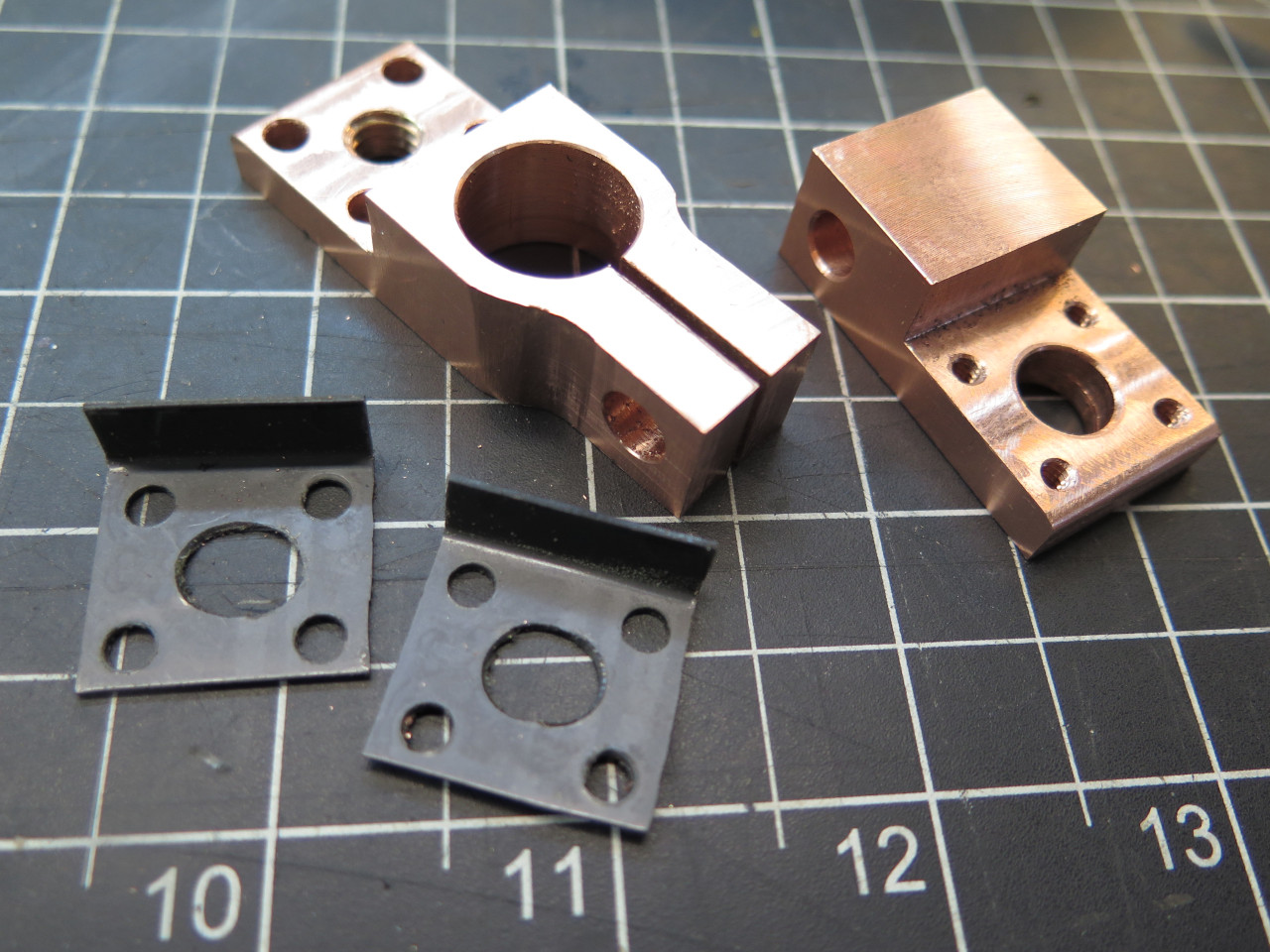
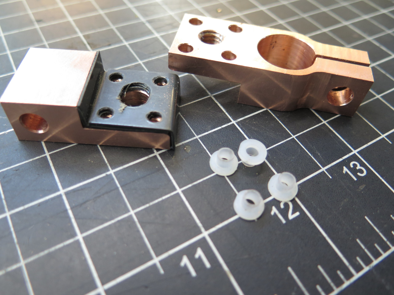
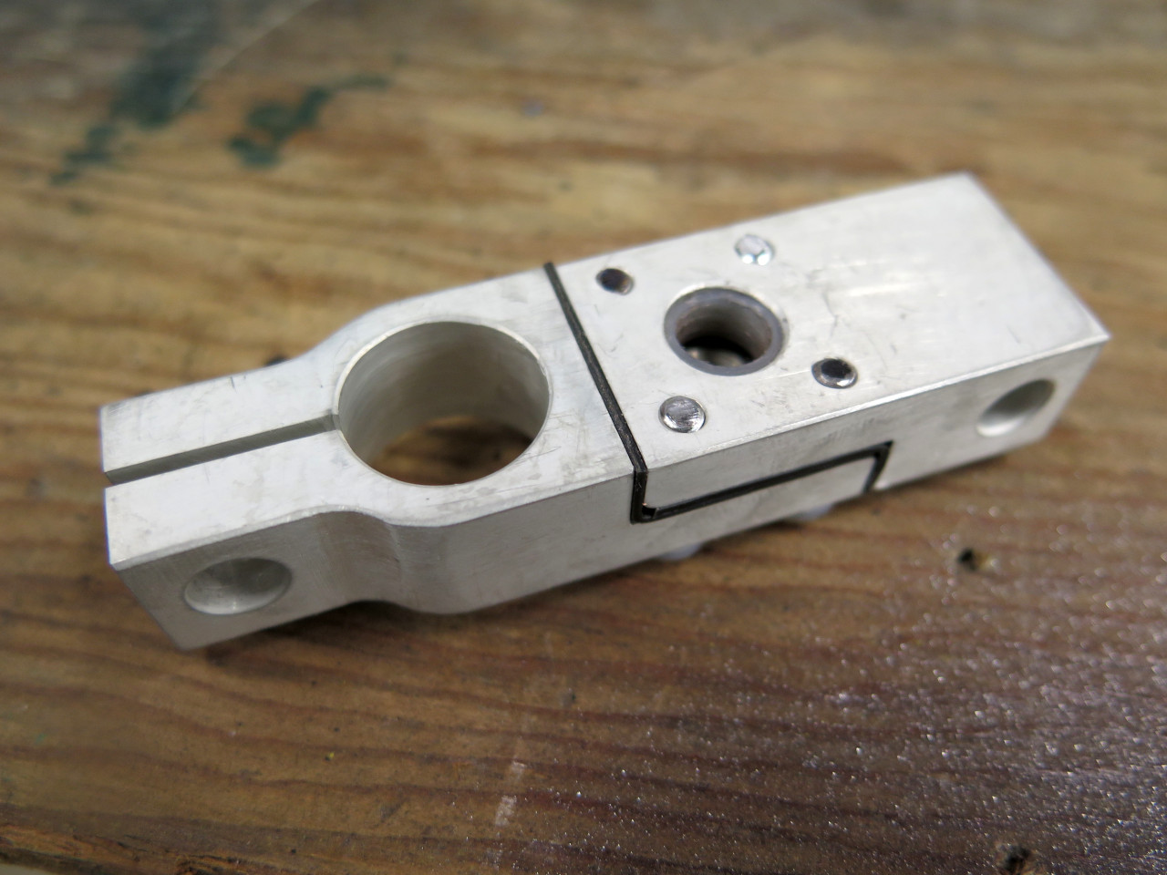
The two parts of the terminal are separated by some nylon spacers, and
fastened together with screws with insulating grommets under their
heads. This makes a solid block with the ends electrically
insulated from each other.
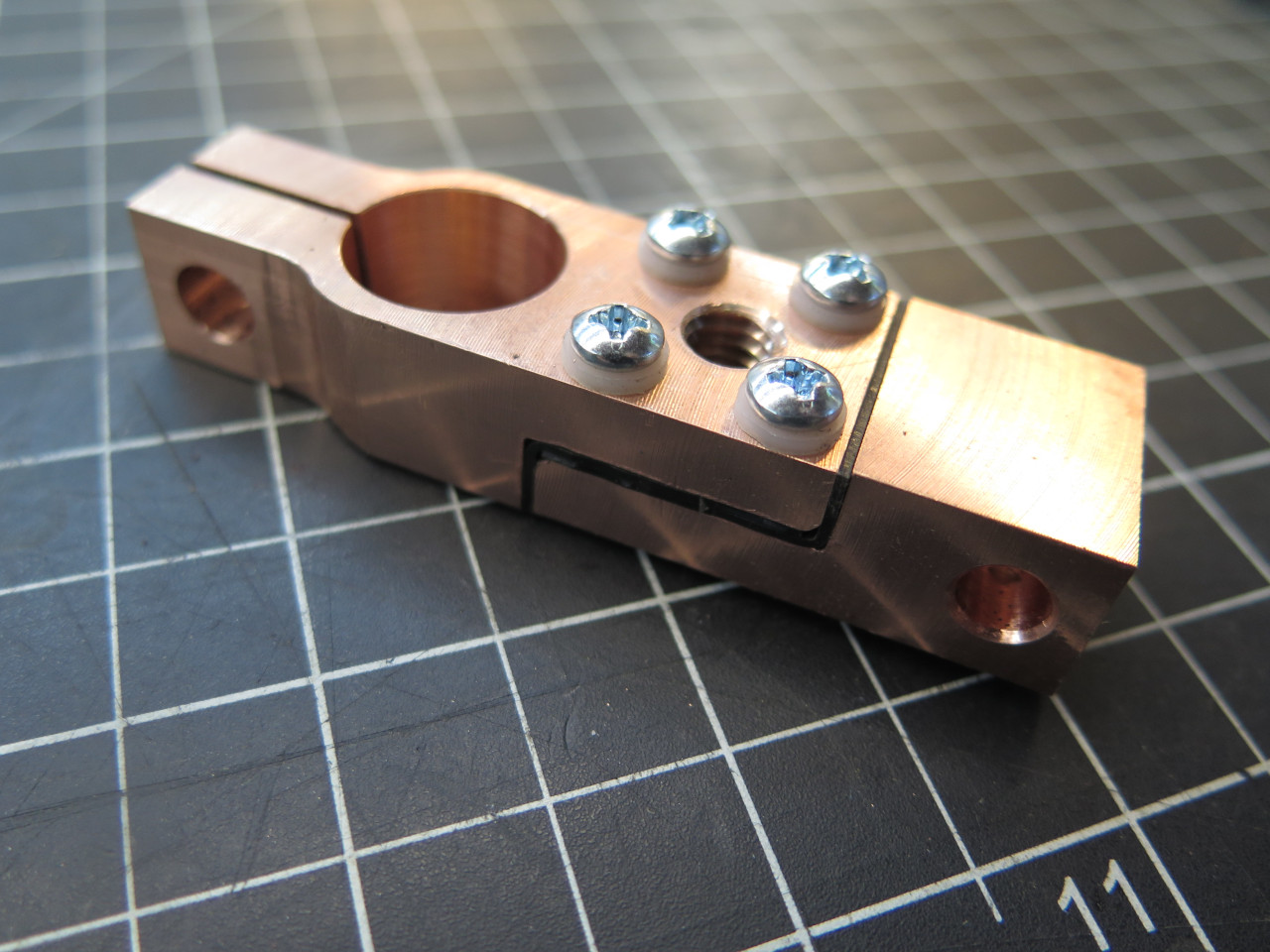
Though it shouldn't be necessary, an insulating sleeve is inserted in the top hole.

I thought I'd gotten away with a picture perfect build until I went to
screw the knob from the store bought device into the 5/16-18 threads in
my gadget. I was crushed to realize that the knob (which I thought
I'd measured) was a metric M8-1.5.
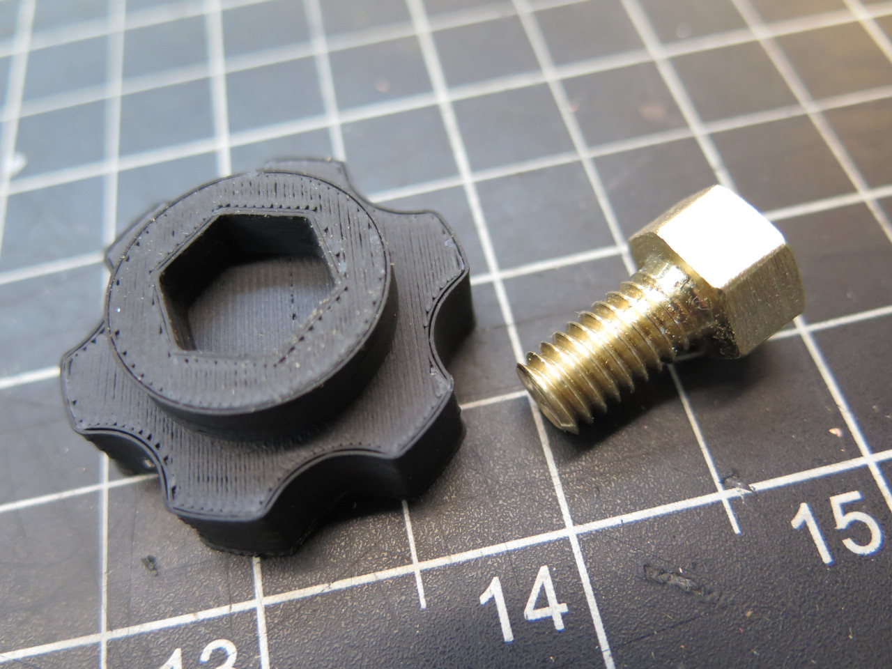
"OK," I said. "I can salvage this. I'll just knock out that metric brass stud and make a new imperial one."
Two minutes later:
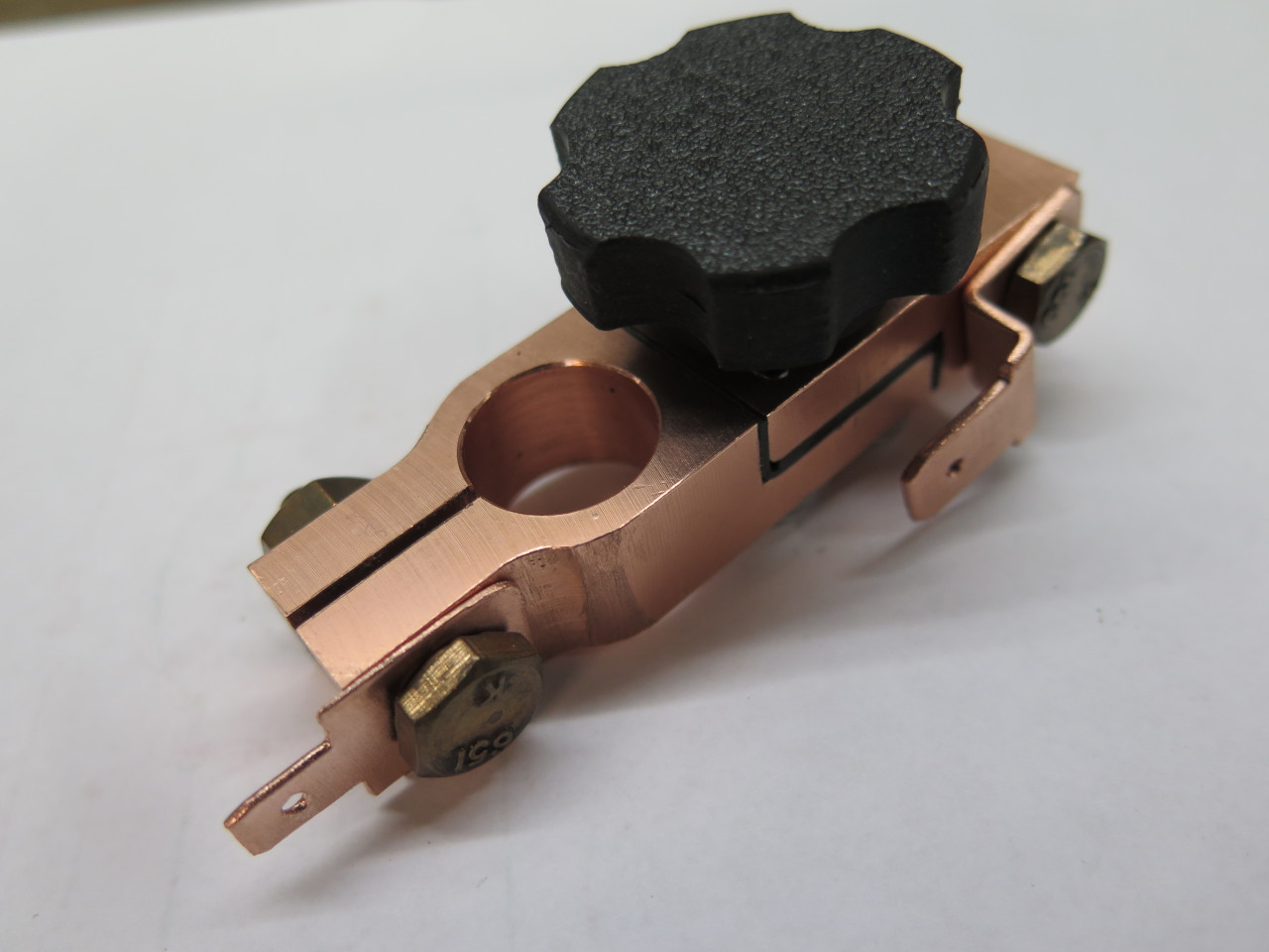
So I had to backtrack and make a brass stud and a 3D printed knob.

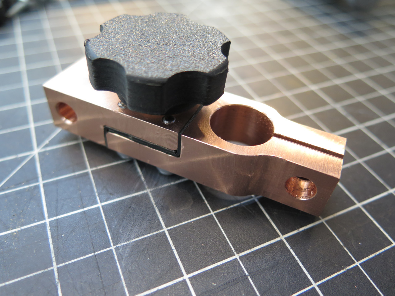
Then some copper tabs for the three smaller wire connections. I
wanted the battery tender to work even when the battery disconnect is
open, so that tab had to be on the battery side of the shut-off.

On the battery. The black wires sort of disappear in the pic, but
the bottom left wire goes to the Power Module and the top left wire goes
to the Battery tender. The large wire on the bottom right goes to
the starter mounting bolt, and the smaller bottom right wire goes to
the alternator.

The bottom ends of the starter cables.

Everything then came off and got disassembled for a nice tin plate to protect the copper from oxidation.
Battery work done. I can even keep it charged until I need it.
This was a fairly involved project. Even I consider making the
battery terminal a little over the top. It does exactly what I
want it to do, though.
Comments to Ed at elhollin1@yahoo.com
To my other GT6 pages.