March 9, 2013
Under Floor Dust Collection
[Click the pics for larger view]
My
wood shop is in the basement of our house, and with very few
exceptions, I consider this ideal. It is heated and air
conditioned 24 x 7 x 365 at no extra cost, I have hot and cold running
water in a shop sink, a full bathroom with a shower, telephone,
internet, and plenty of AC power. I can be in my shop in 15
seconds from anywhere in the house, in my underwear if I want.
From my wife's point of view, there are some
drawbacks--in a
nutshell, they boil down to noise, dust, and odors. While
we've
come to some understandings on these points, she does acknowledge that
it is handy to have me accessible for dire domestic emergencies like,
say, a spider in the sink.
One drawback I see is the
concrete floor. If I ever built a detached shop, and
this isn't likely, I'd have a
crawlspace, or at least a false floor to allow underfloor routing
of AC power and dust collection ducts. The concrete
floor
makes this harder--harder, but not impossible. When I got a
new
table saw ten or so years ago, I tried for a while to make overhead
dust collection ducts work. The ducts were unsightly, always
in
the way, and just generally a hassle. Likewise with the power
cord.
I finally took what many (including me at the time) would
consider an extreme measure: I broke up enough of the
basement
floor to install a dust collection duct and AC power to the table saw.
The job
took a few days, and while a little dirty at times, wasn't all that
hard or complicated. I ended up considering it time and
effort
well worth it.
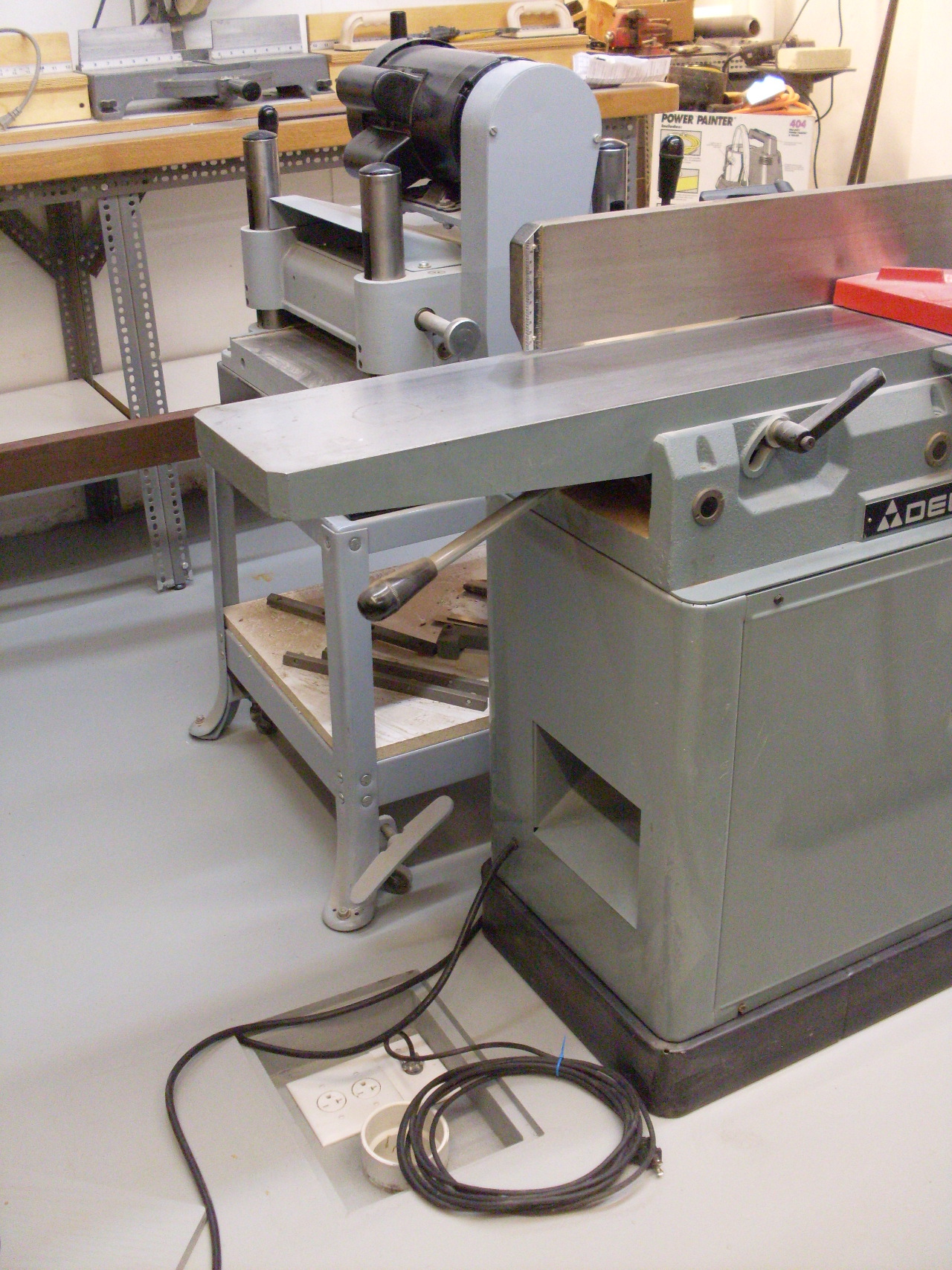
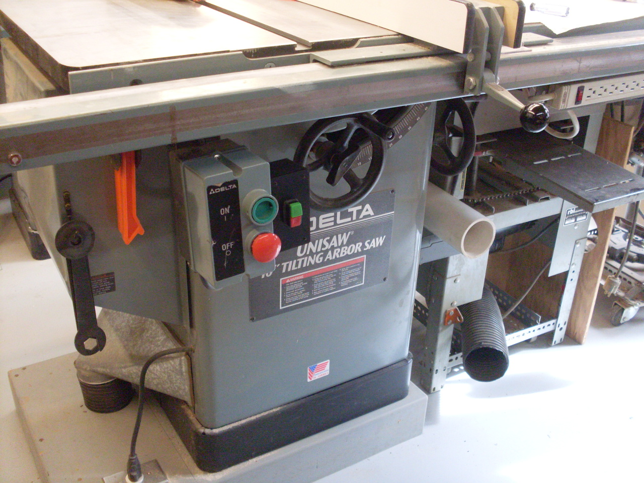
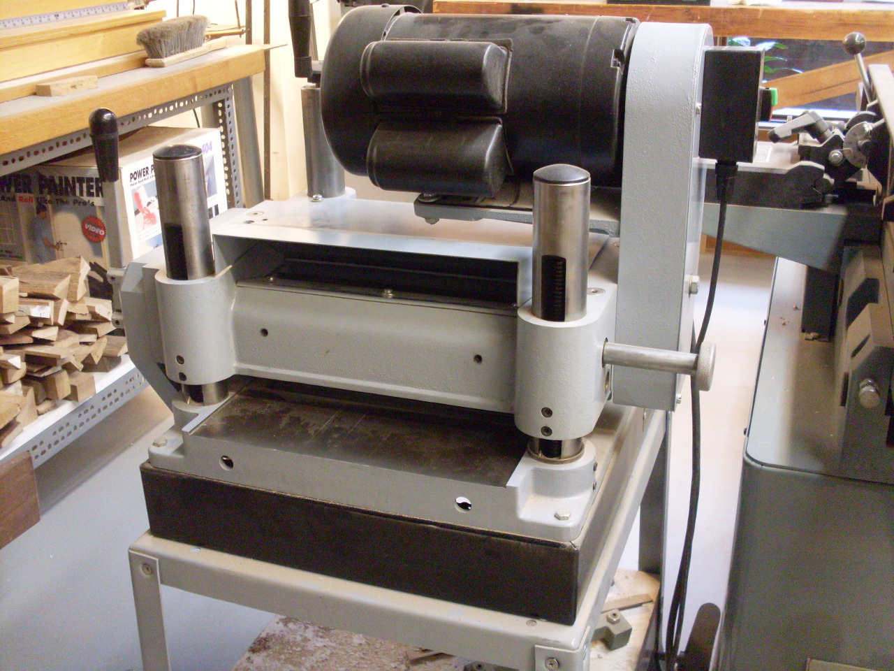
When I got a new Delta RC33 planer (new to me--it's 30 years old [here's a link
to the rebuild of the machine]),
I wanted to put it and my jointer in the middle of the floor.
Since these thing each can put out prodigious
amounts of
wood dust and shavings, they really need good dust collection, and I
decided without hesitation to extend the underfloor system.
The
following is a story about the experience.
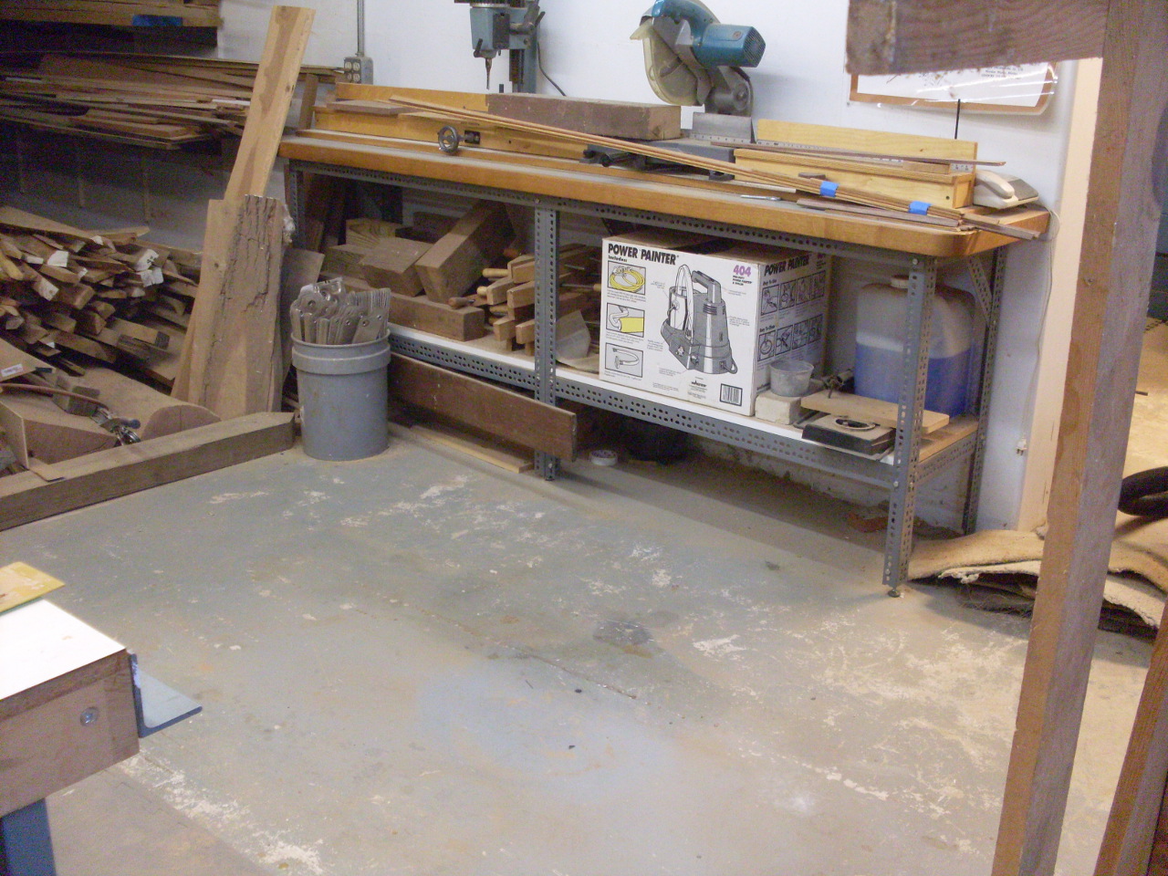
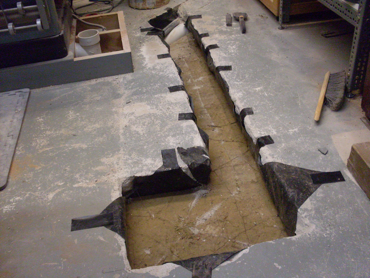
Here is the area
I cleared out to put the planer and jointer. It's about six
feet
from the table saw, which has an underfloor duct that I would tap into.
I marked out on the floor where the concrete would have to be
broken out.
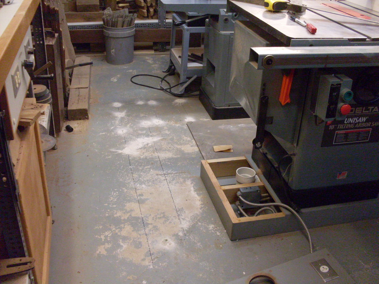
I
broke quite a bit of it out with just a small sledge, but since I
wanted to do the whole thing while my wife was gone for the
weekend, I rented a small jack hammer that finished the rest pretty
quickly.
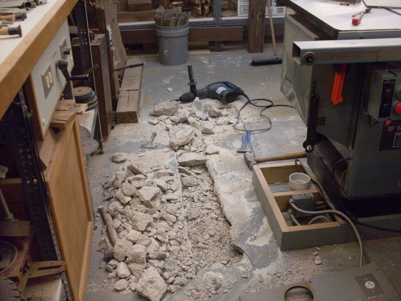
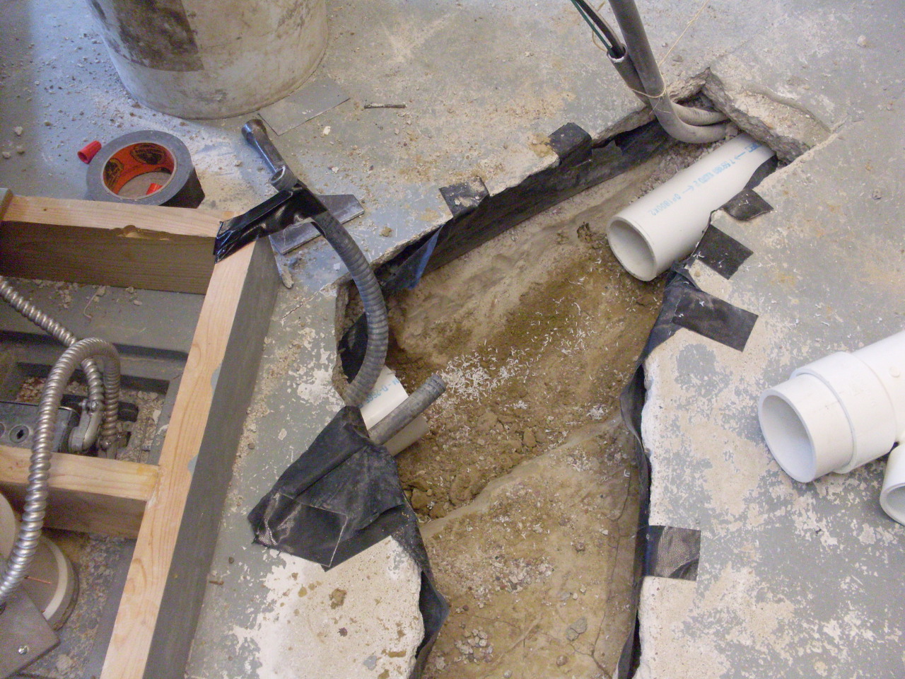
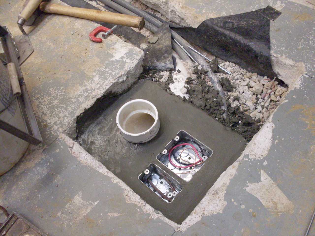
Here
is where I had to tap into the existing duct and conduits.
One
conduit is for AC power, and the other is for low voltage control wires
to remotely turn the vacuum system on.
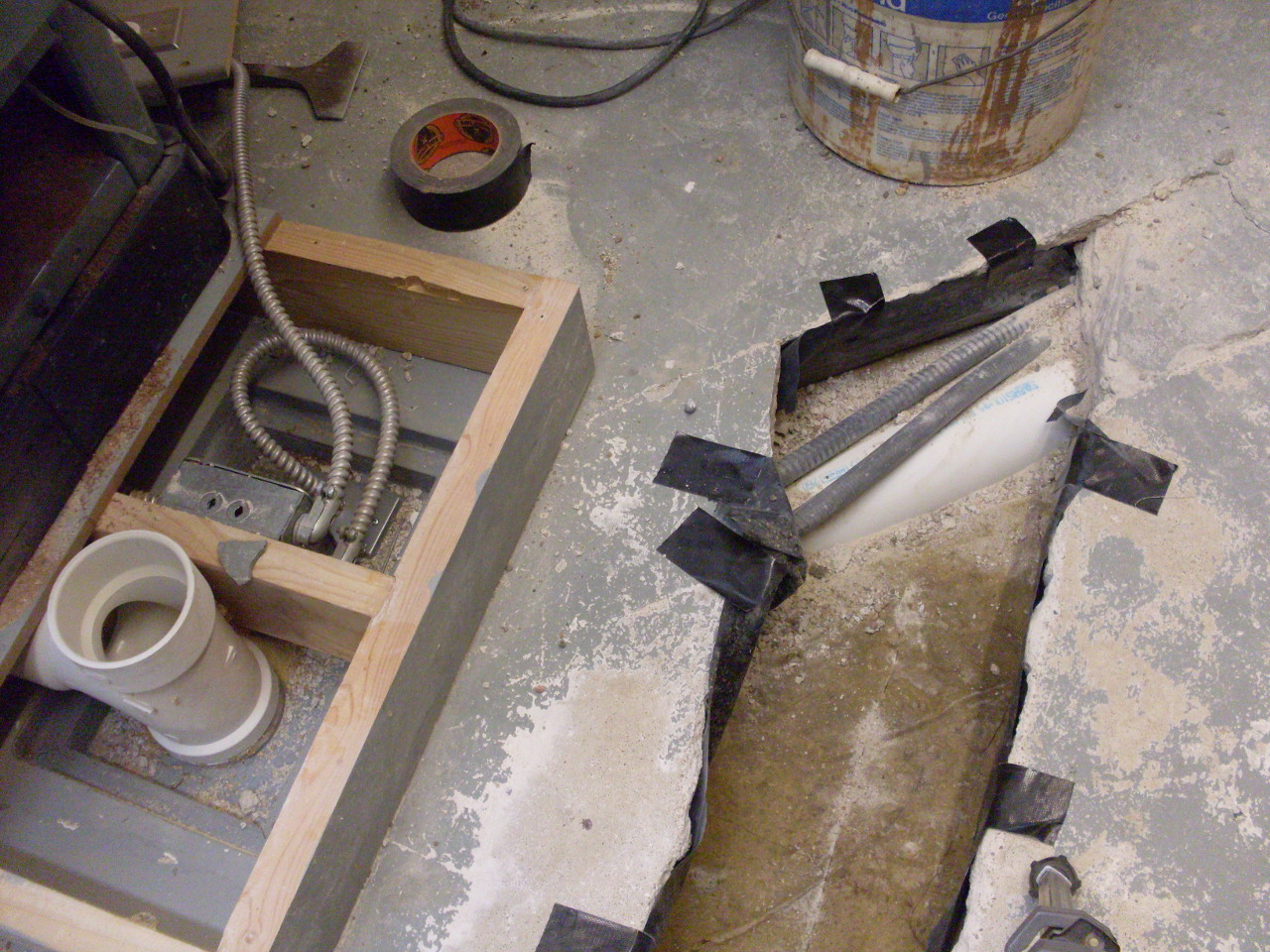
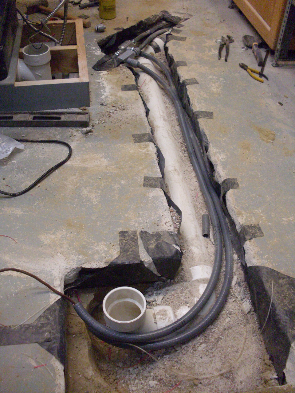
Cleaned
up the debris, and leveled the bottom of the trench at the right depth.
The near end of the trench is where the floor access box will
be.
There wasn't a good way to glue the joints of the "Y", so I assembled
them dry with slip couplings and taped them.


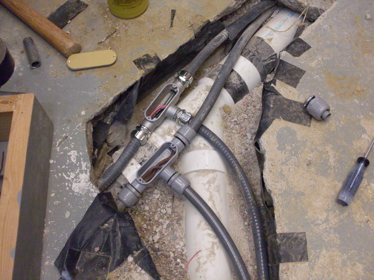
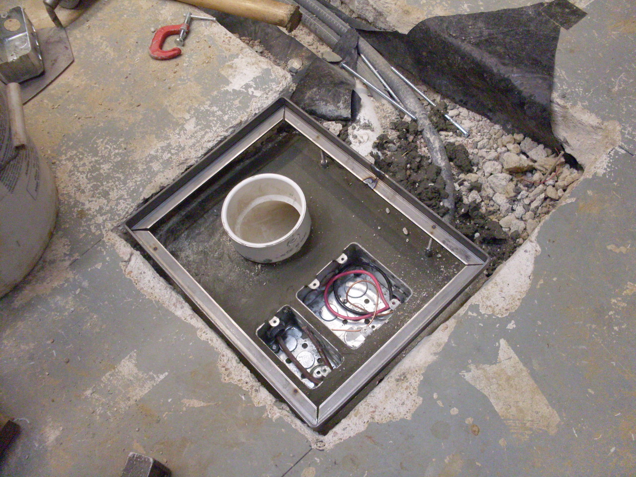
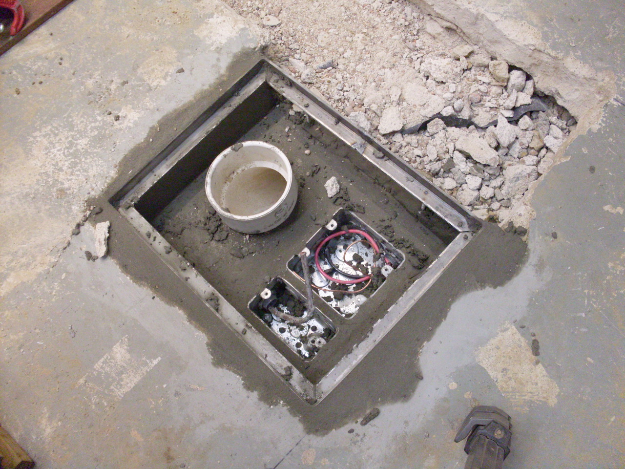
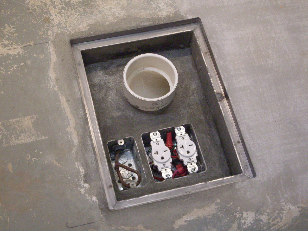
Then
ran the conduits. I used a double box for the AC so I could
plug
in both the jointer and the planer, and a single box for the control
circuit.

I
set the duct and boxes in concrete that would form the floor of the
access box, then set an angle iron frame to form a lip for a cover for
the access box. I backfilled the trench
part way with
gravel and some rubble from the demolition...
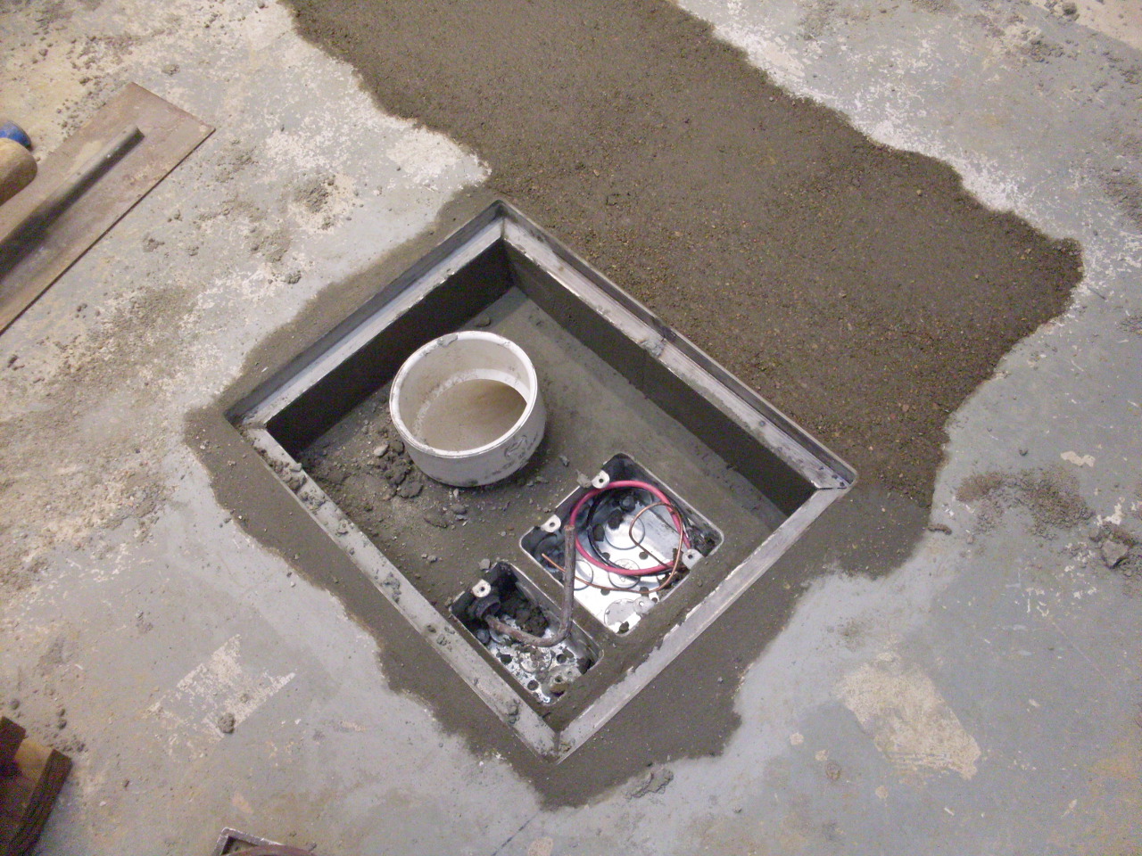
...and then poured concrete to the floor level. I got to this
point in a single two-day weekend.

Installed two 20 amp, 220 volt recepticles. They are wired in
parallel on the same circuit.
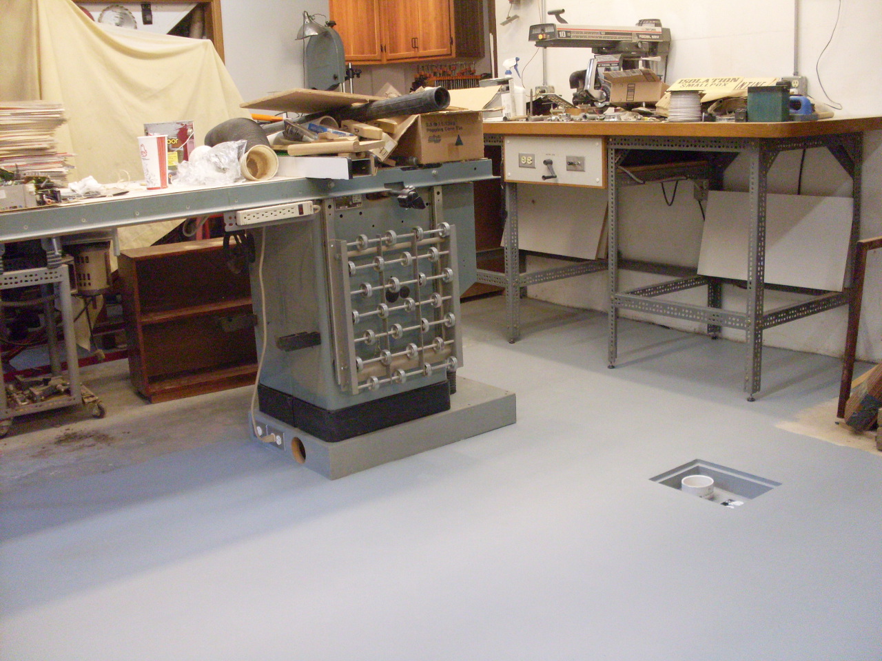
Decided to paint the entire floor while I was at it.
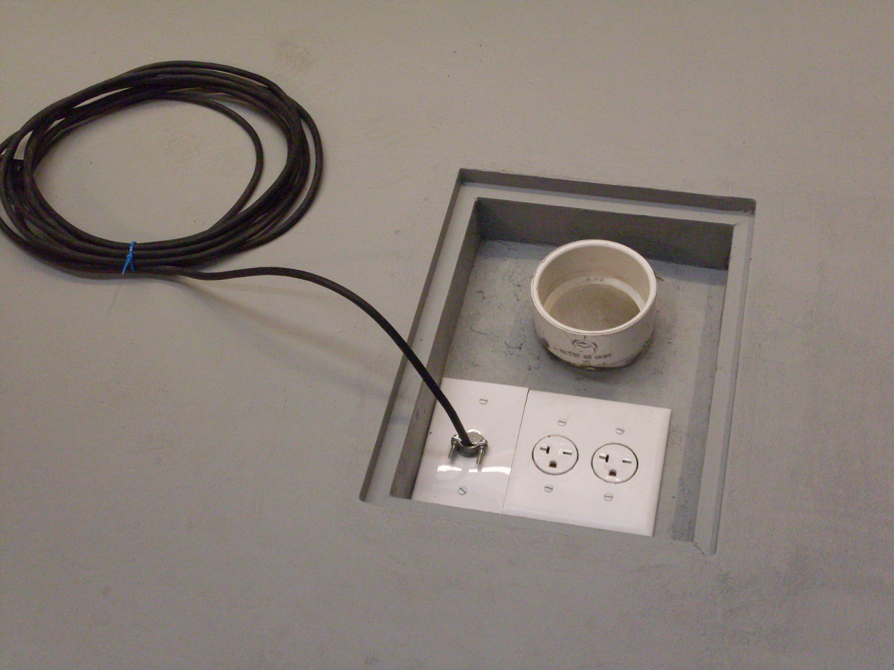
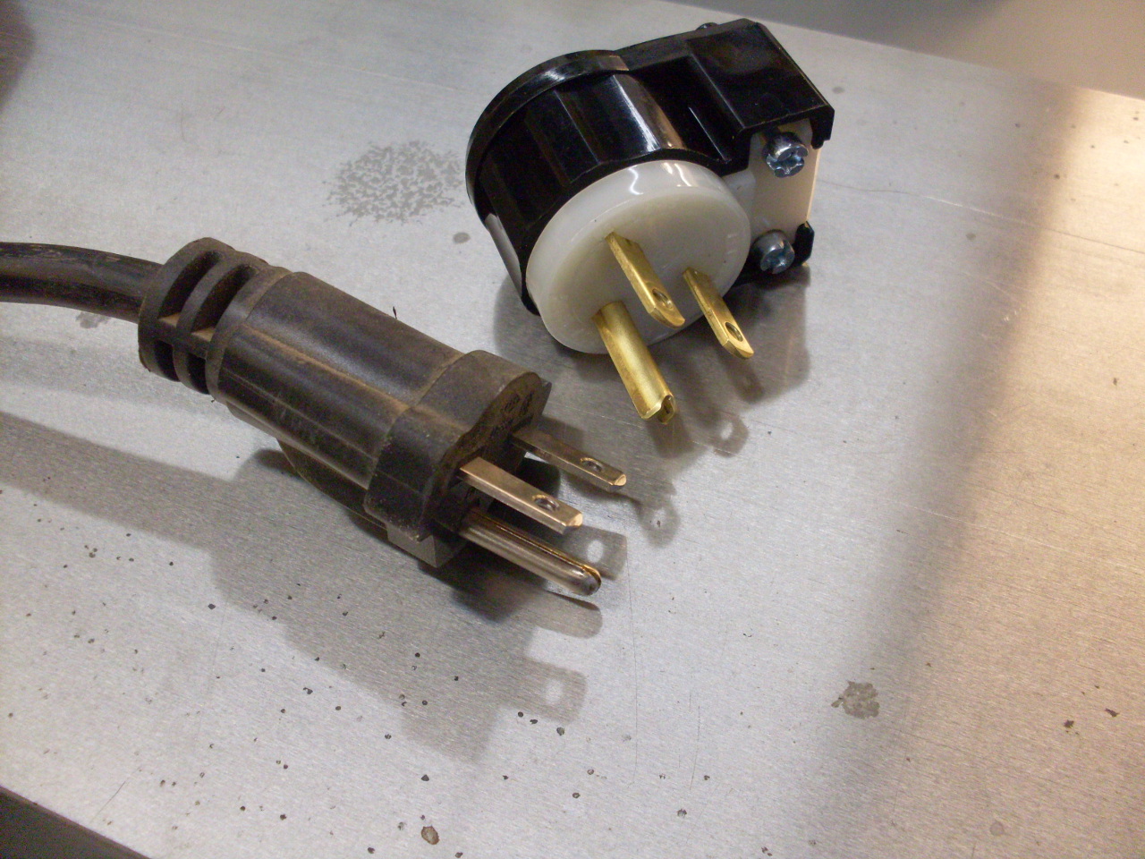
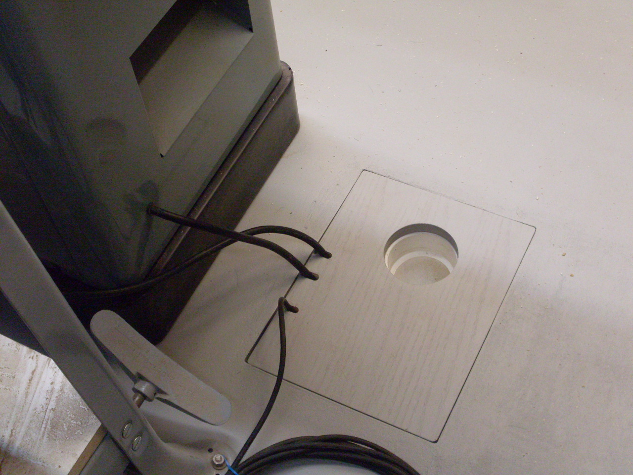
Added
cover plates and a floor cover for the access box. There
wasn't
clearance for the power plugs on the machines, so I swapped them out
for right angle ones.

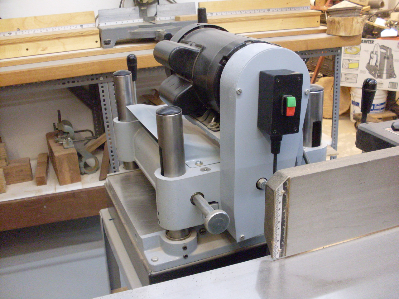
Moved
the machines into place. I had to move the power cord of the
jointer so it exited on the chute end of the machine.

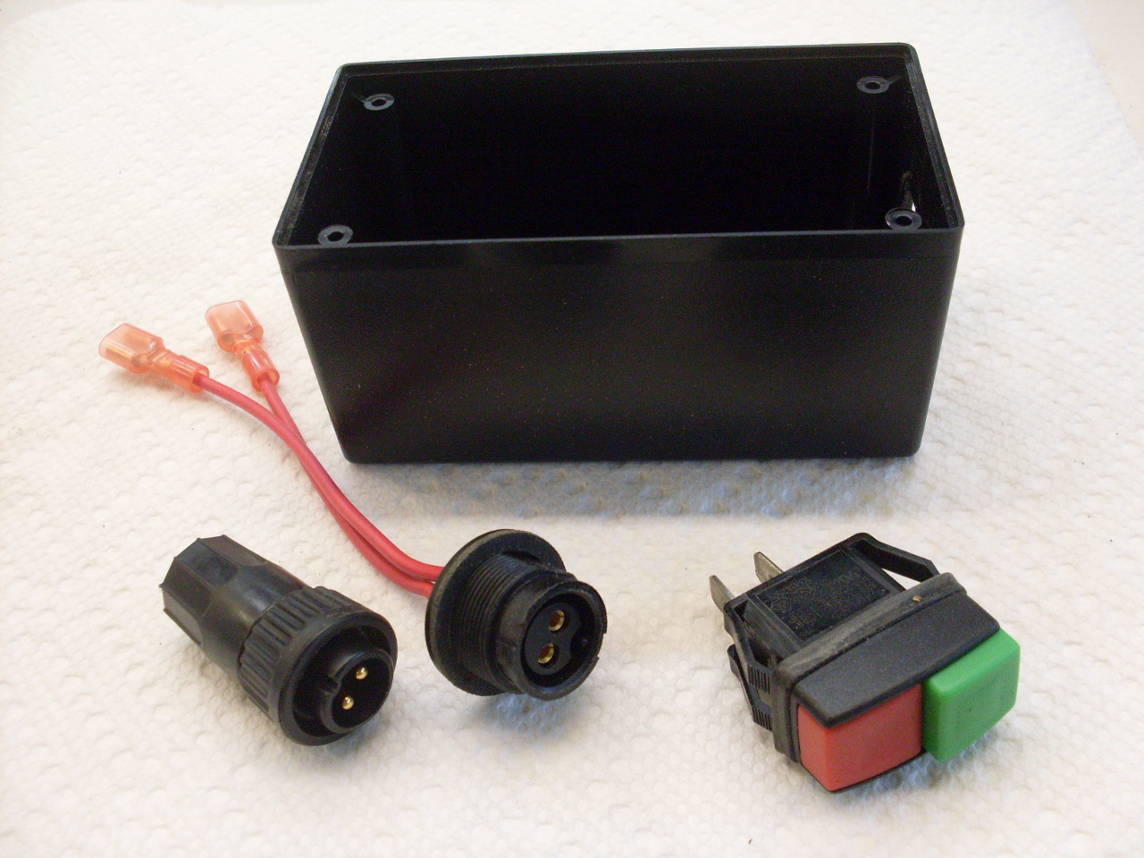
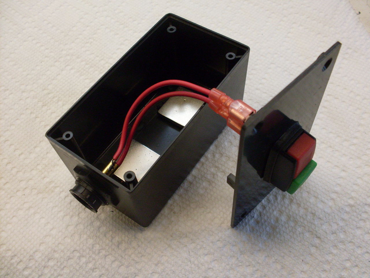
I
made some little control boxes to turn the collection system on and
off. I had a switch on a far wall before. This will
be
better. The box on the planer has magnets inside so it just
sticks to the belt guard. The one on the table saw is
attached to
the existing control box with nylon hardware.
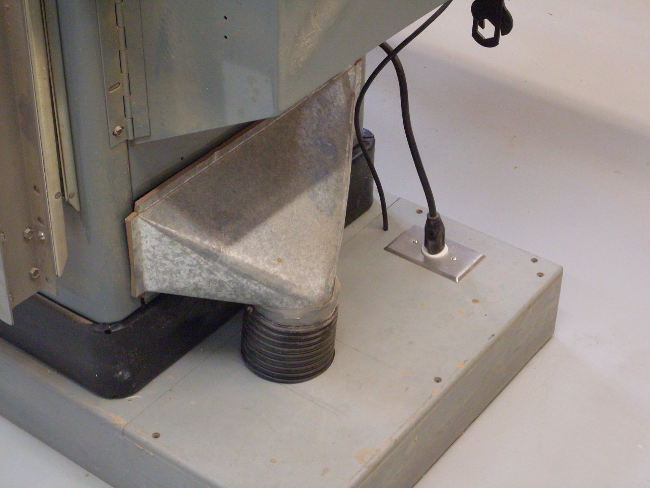
This
is the custom duct transition I made for the table saw years ago.
Normally there are little clips that hold it tighter against
the
cabinet. The transition for the jointer is obviously
different.
For
some reason, I still remember how to do sheet metal transition design
from drafting class in highschool. It's a skill that's come
in
handy a number of times.

Since
the table saw, jointer, and planer are all on the same duct, I have to
have a way to block individual machines. I had a few blast
gates
around from my previous overhead system. I modified one
slightly
to use here.
The jointer is hooked up. The planer goes on the other
branch.

The dust chute exit on the planer is very clodse to a standard 2-1/4 x
12 rectangular duct size, and it's pretty common to just use a standard
sheet metal register boot to transition to a round outlet to one side
or the other.
That was
my first plan, but all my usual sources only had transitions to 6"
round duct, and by the time I put a reducer on it to 4", it made the
angle for the flex hose kind of awkward, and the whole
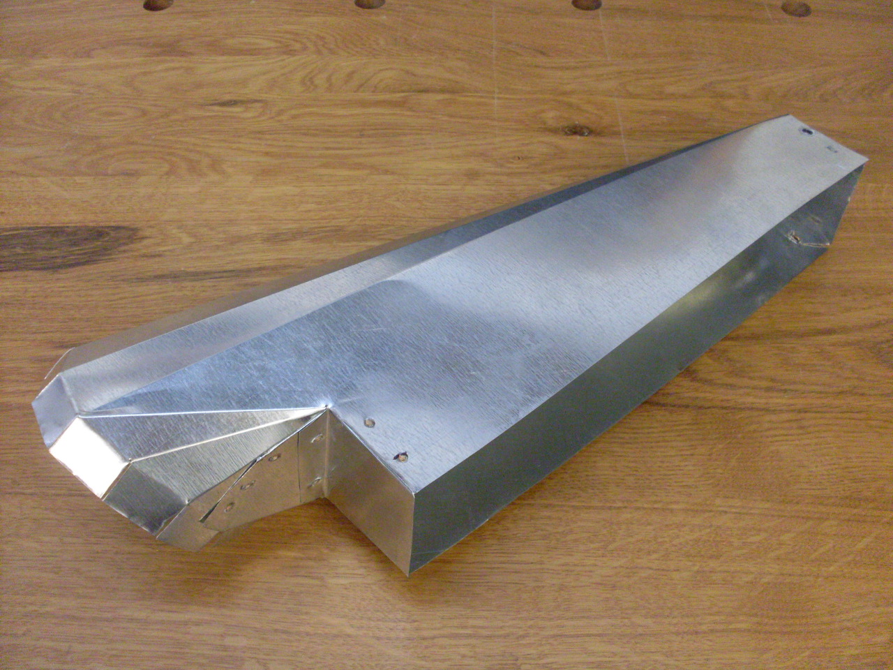
setup was looking pretty kludgy. I decided it wasn't
that much work to make the transition, so I sketched out something that
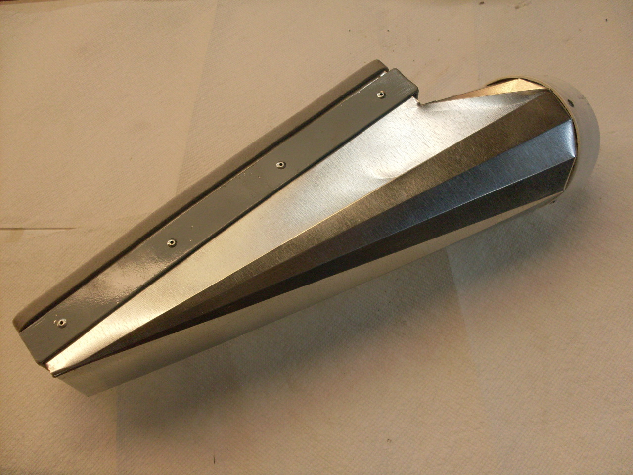
would work. It would be a transition from 2-1/4 x 12
rectangular to 4" round on the right side, but the round outlet would
be facing 45 degrees down to help the hose connection.
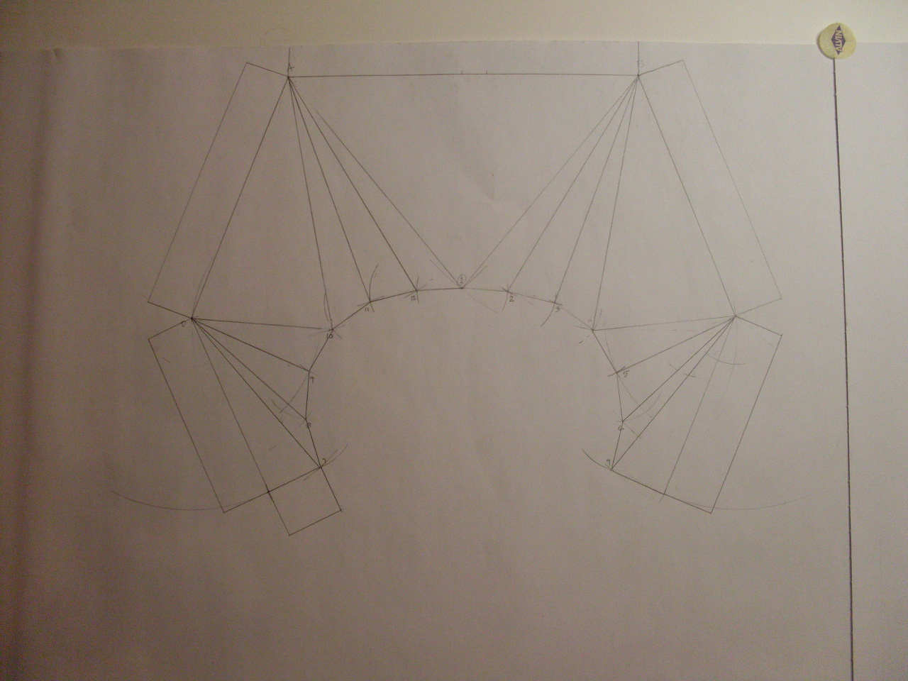
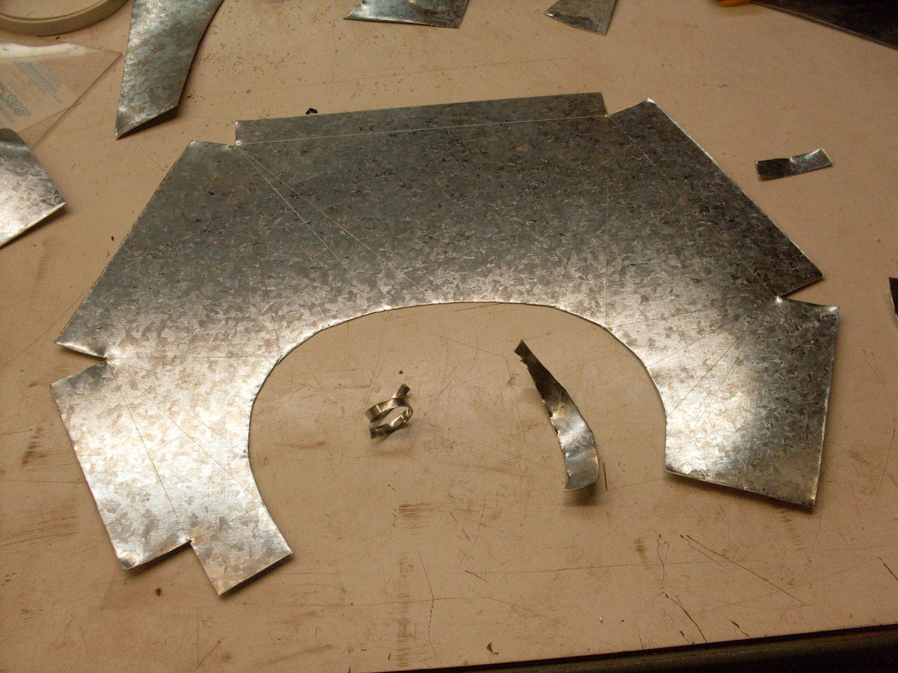
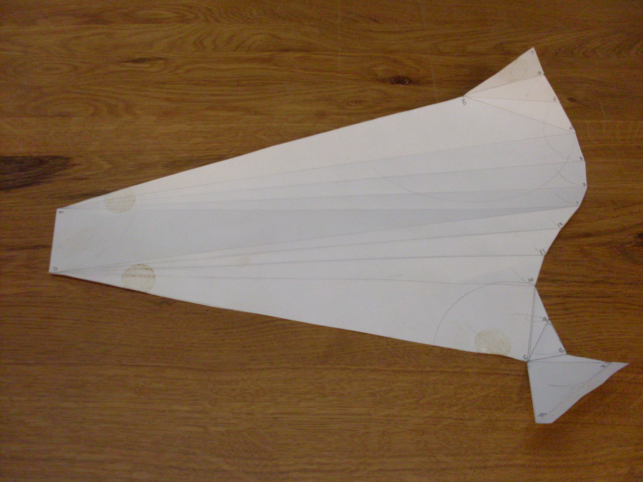
The layout of this
transition was a lot more complicated that the one for the jointer
because it is asymmetrical. A paper pattern ensures that the
drafting was correct.

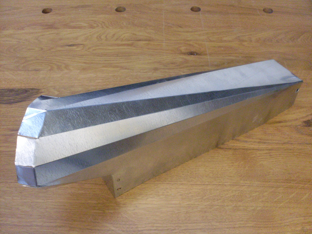
Then transfer to som
thin galvanized sheet, cut it out, and fold it like the paper pattern.
It is hard to visualize without a paper model that some of
the folds have to be reverse. I cut the end off a PVC fitting
and fitted it to the round outl;et to serve as the attachment point for
the flex hose.
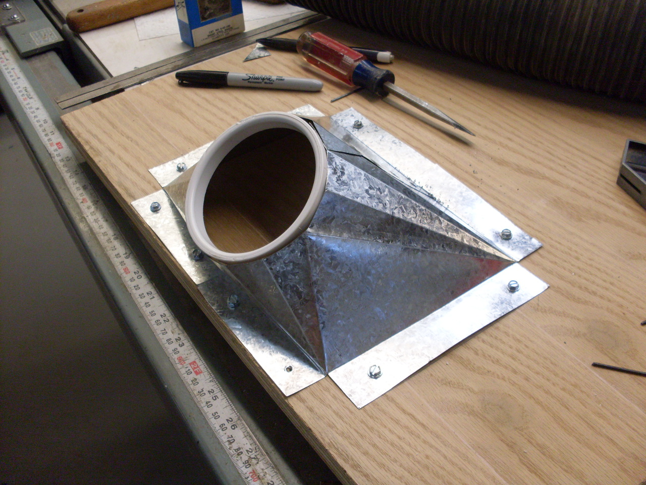
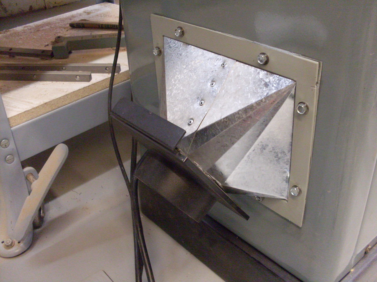
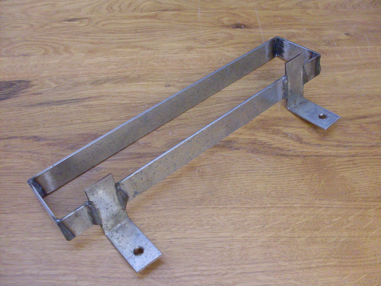
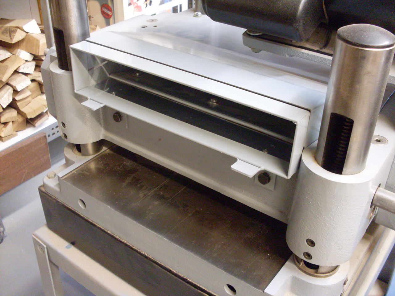
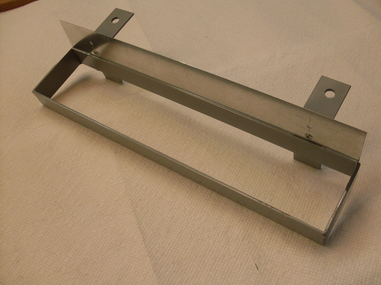
This is the metal frame
to attach the transition to the planer using the existing holes.
One sort of background rule I have for adding accessories to
machines, especially old ones, is to not make any
irreversible changes like drilling holes or welding if at all possible.
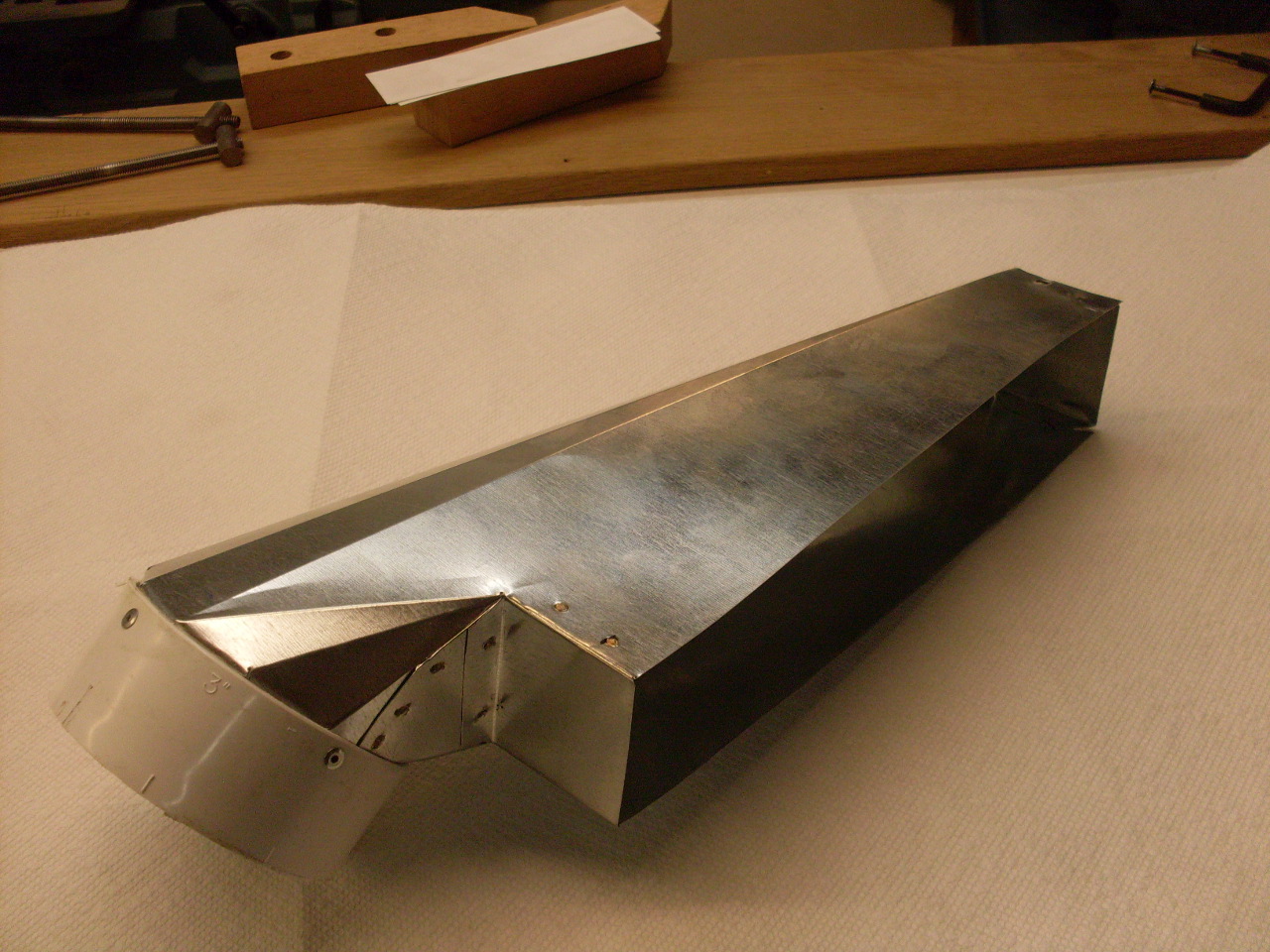
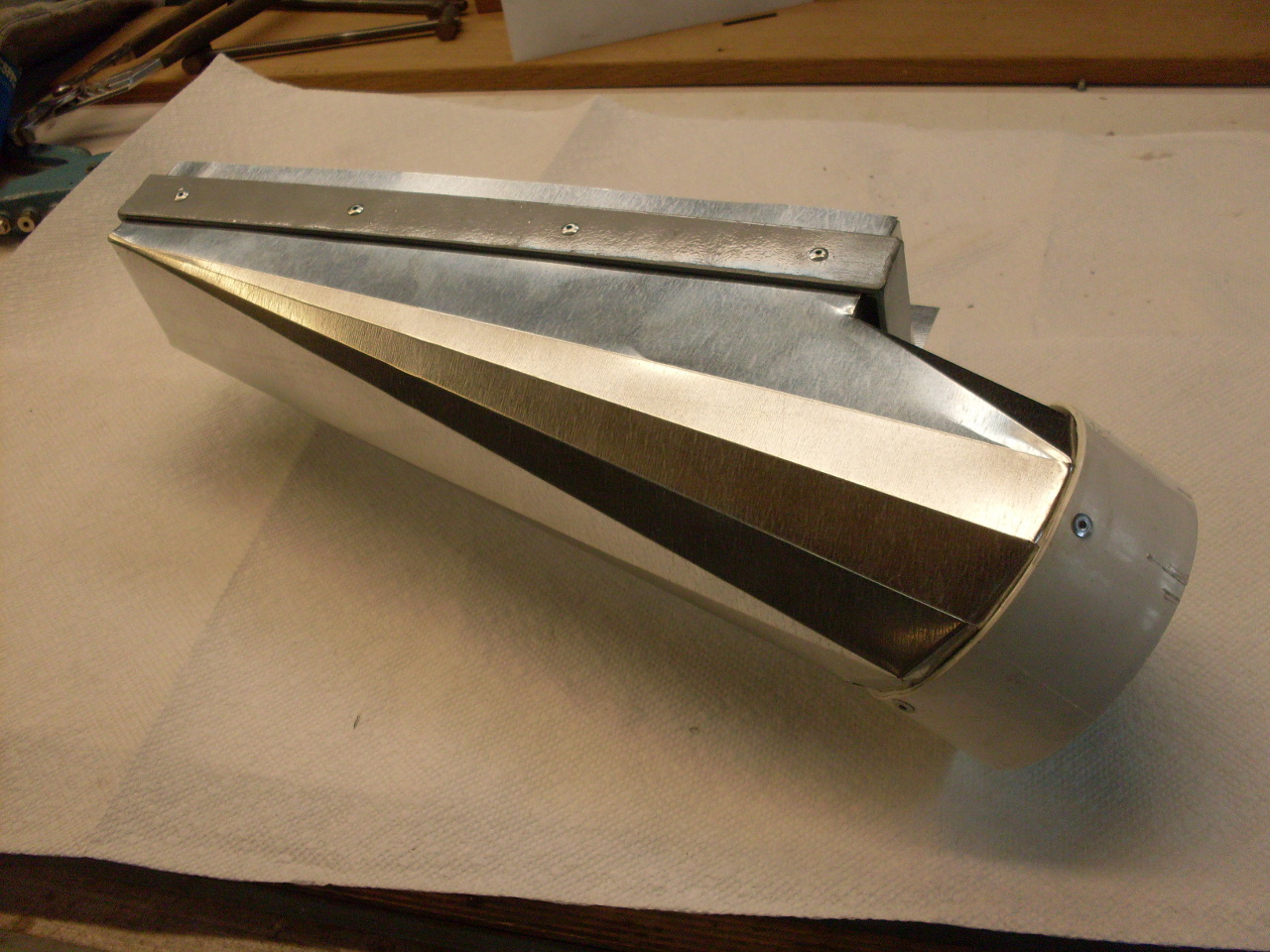
The last pic is a trial fitup of the components.
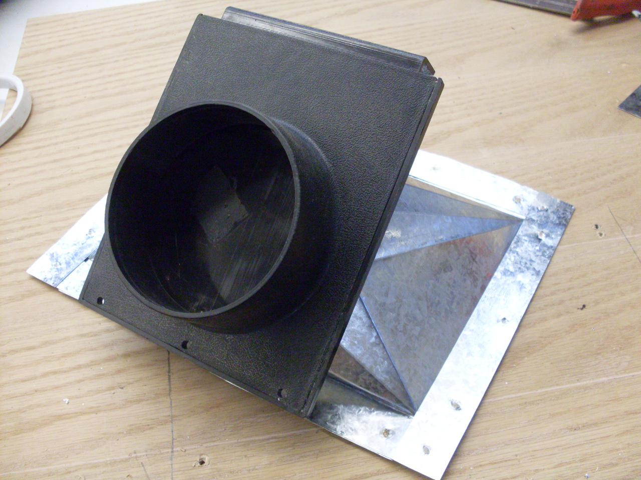
I had to rivet a little
piece of sheet metal to the frame to serve as the bottom of
the exit duct from the planer, then riveted the transition to the
frame. Some foam weatherstripping tape seals the joints.
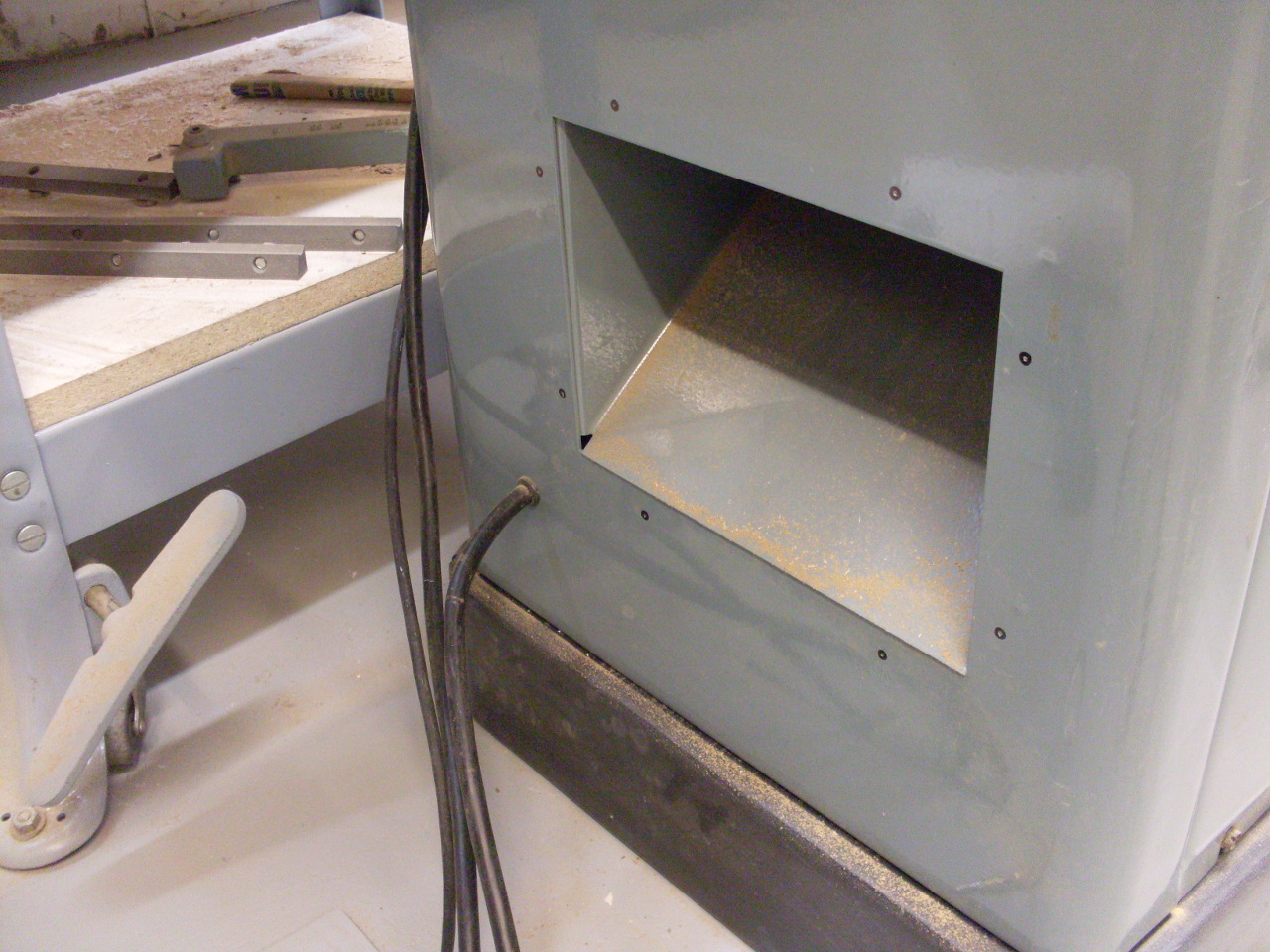
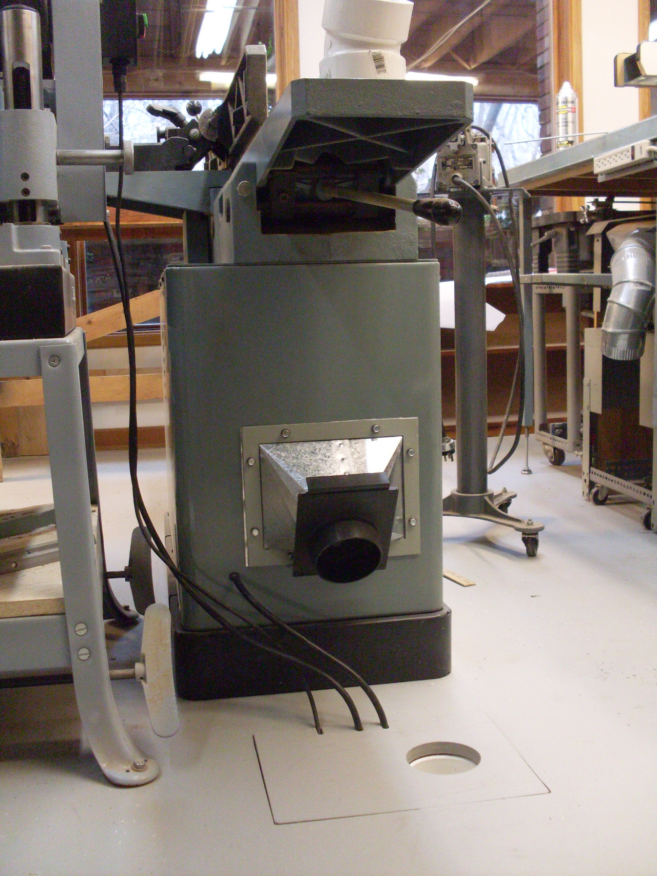
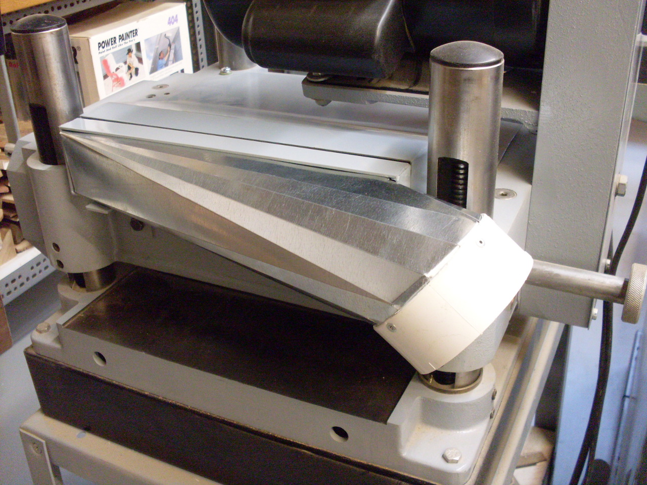
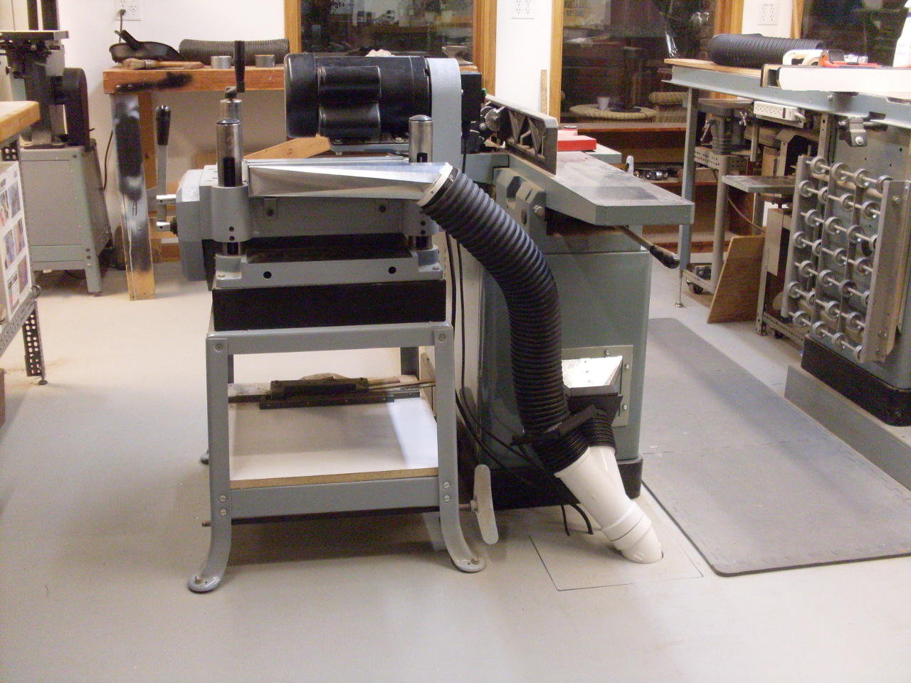
Here is the planer all
hooked up to the in-floor system through a blast gate.
Comments to: elhollin1@yahoo.com