To my other MGA pages
January 15, 2025
Steering Box
Most "sports" cars of this era featured rack and pinion type steering
gear. This arrangement offered quick, responsive steering with
good "road feel".
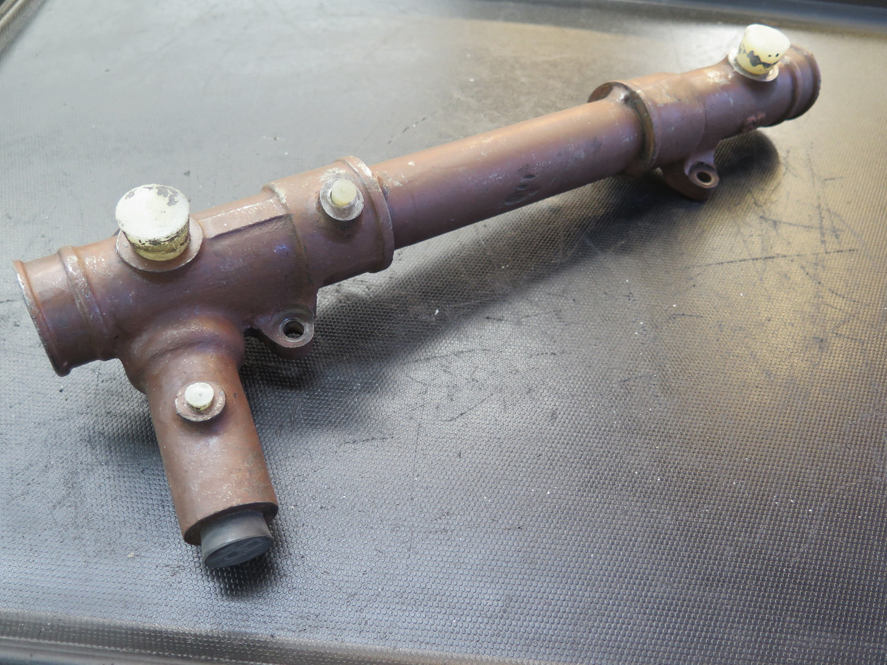
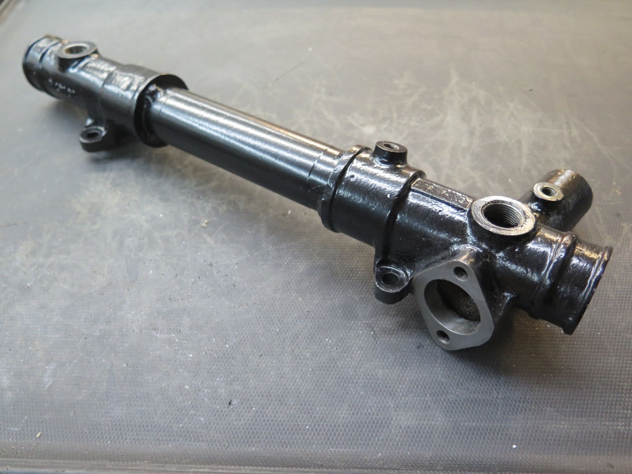
My steering box was pretty crusty, but appeared to be intact.
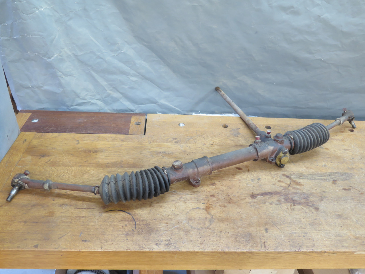
Removing the rubber gaiters revealed the ball joints of the tie
rods, The joints are just threaded to the rack. I didn't
realize at the time that there were lock washers that should have been
released first, so I pretty much destroyed them by unscrewing the tie
rods.
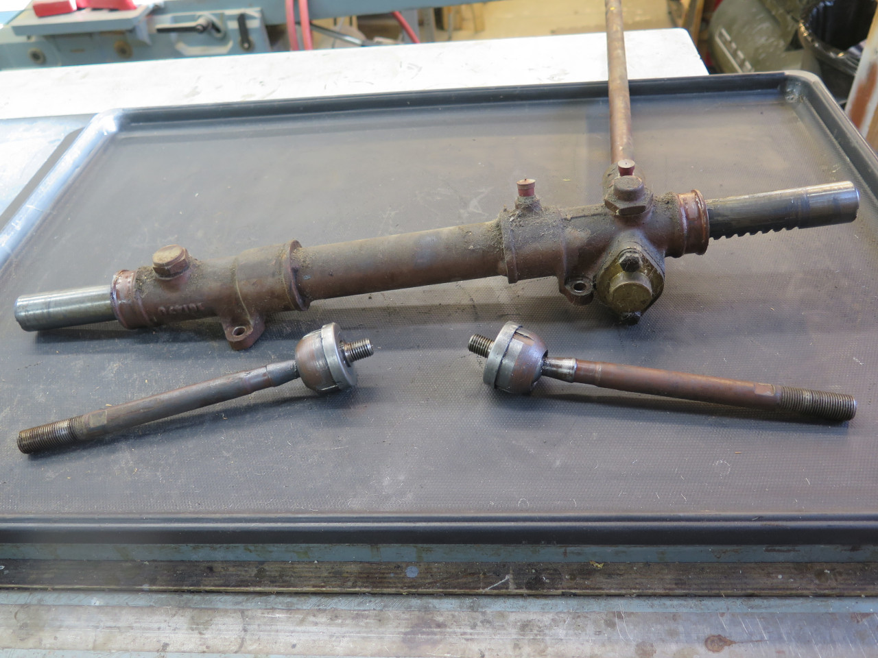

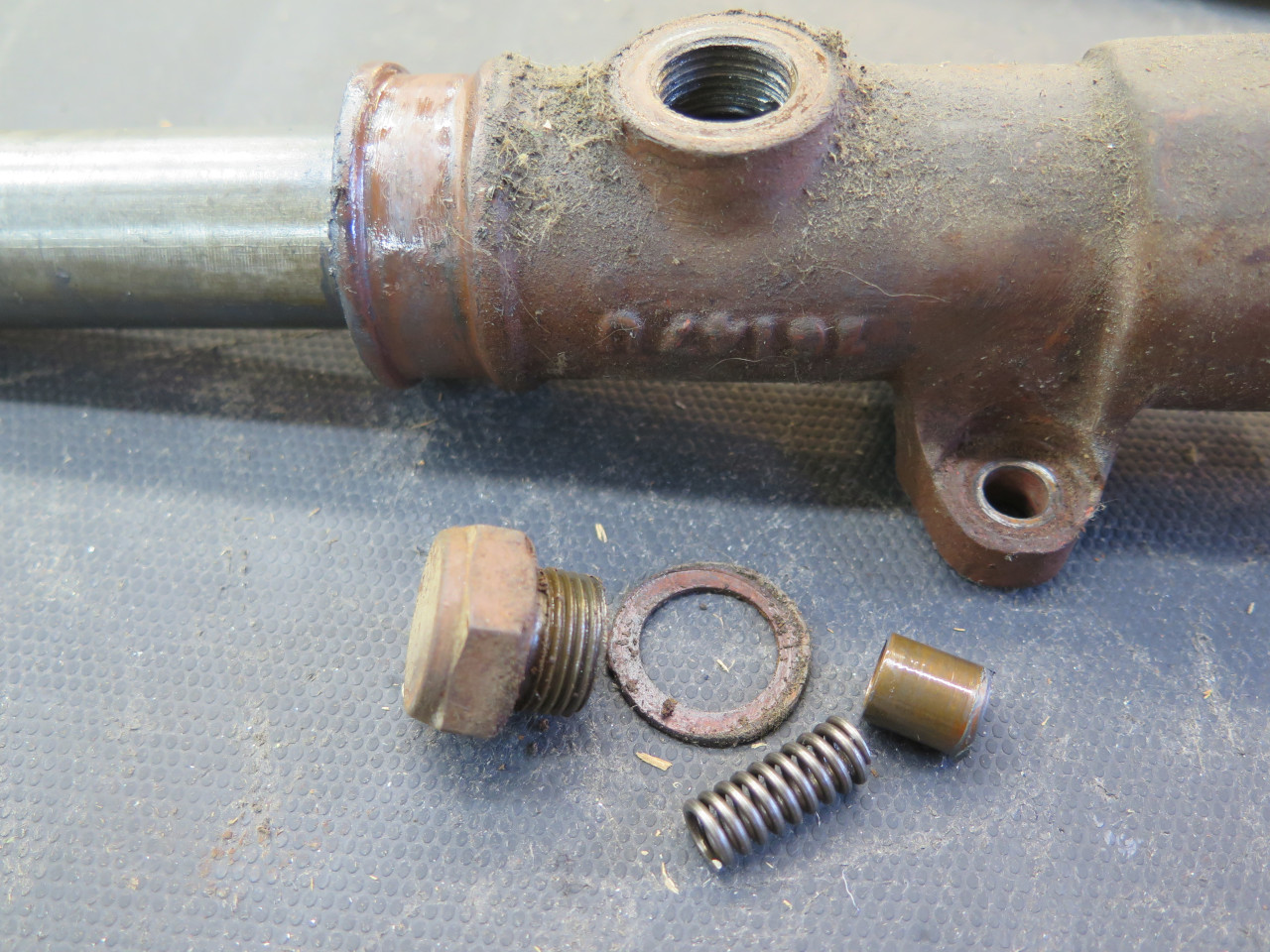
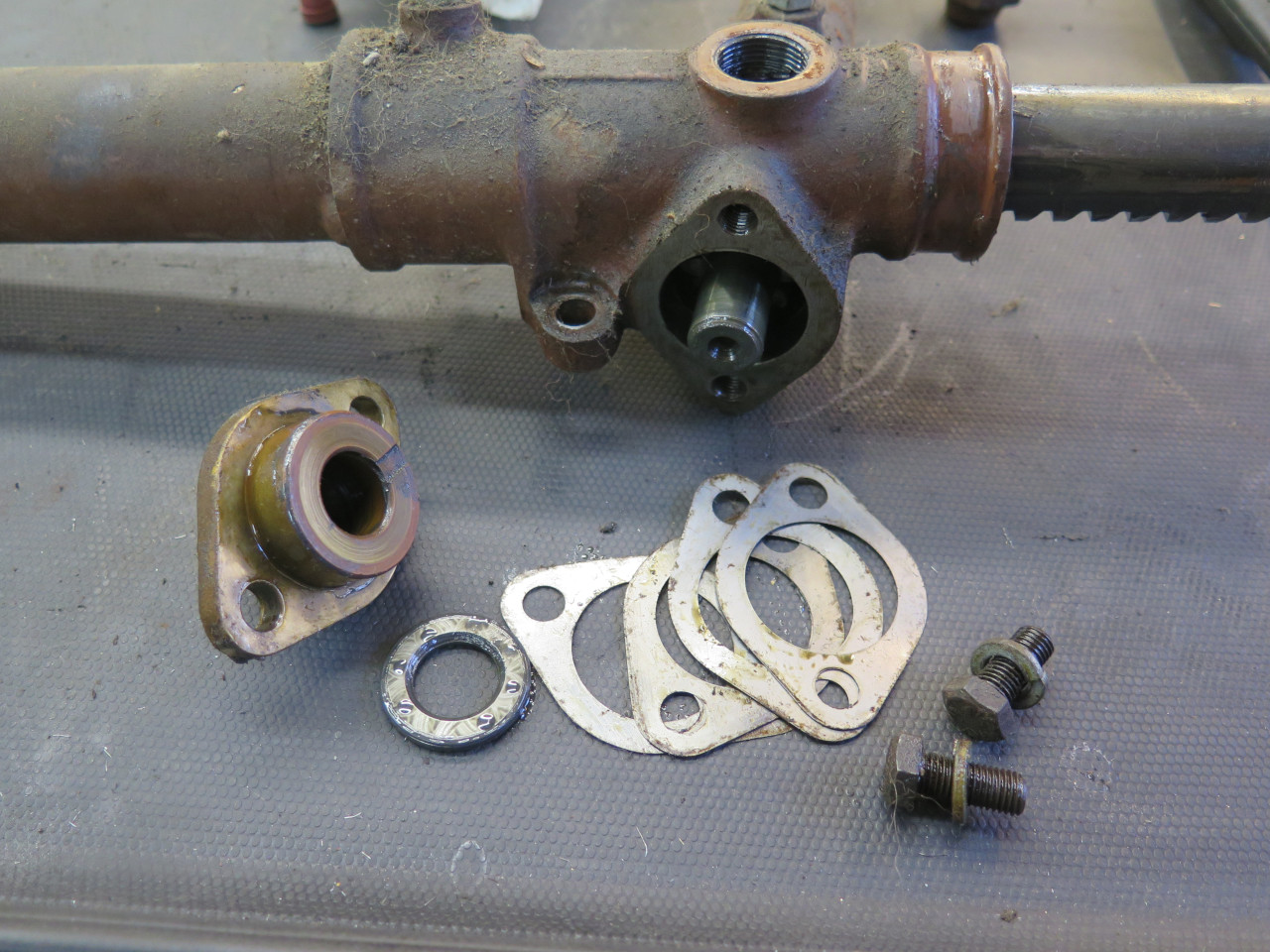
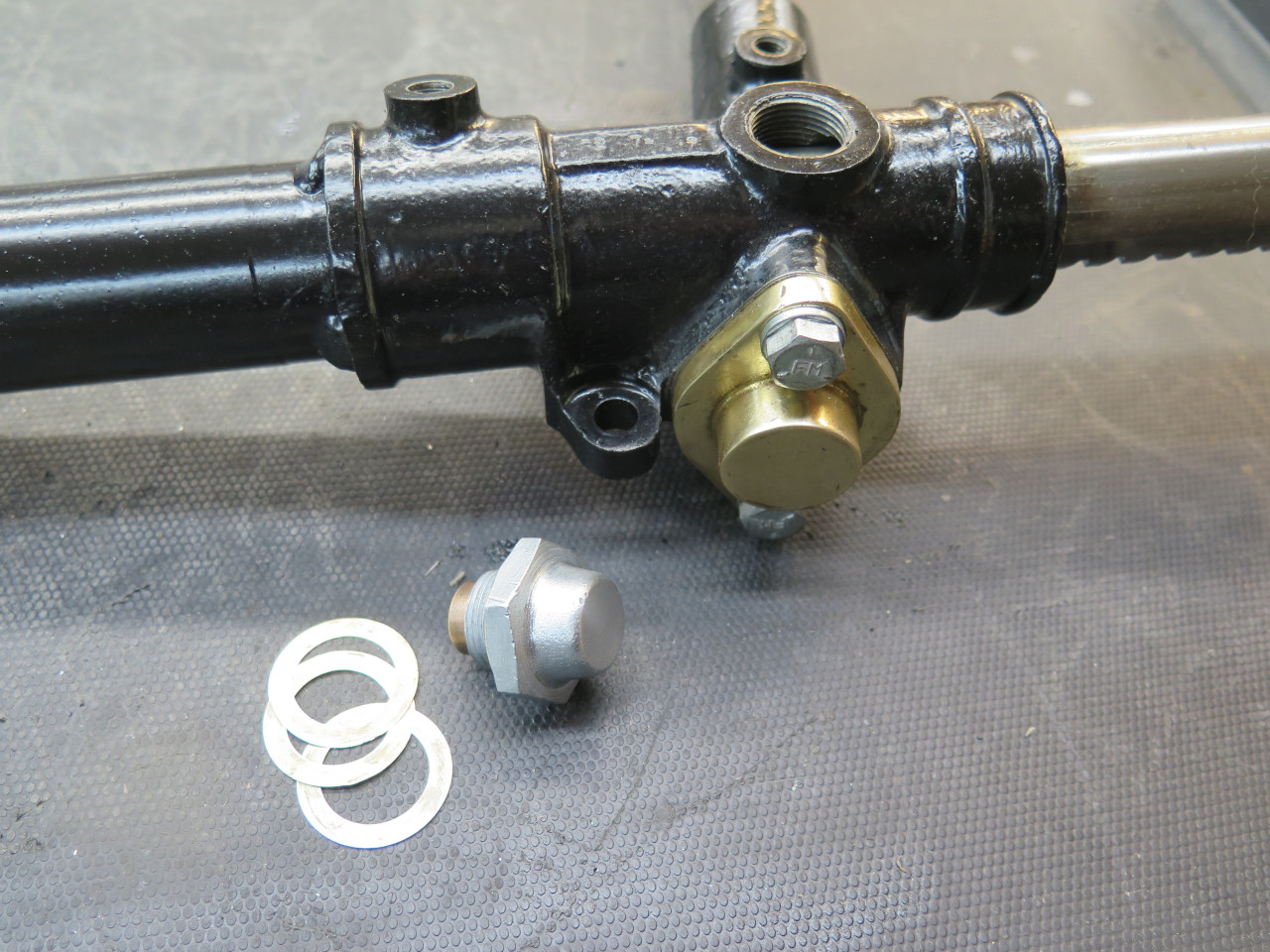
There wasn't really a lot to disassemble. There were a couple of spring loaded damper assemblies.
And a brass cap that retains the pinion.
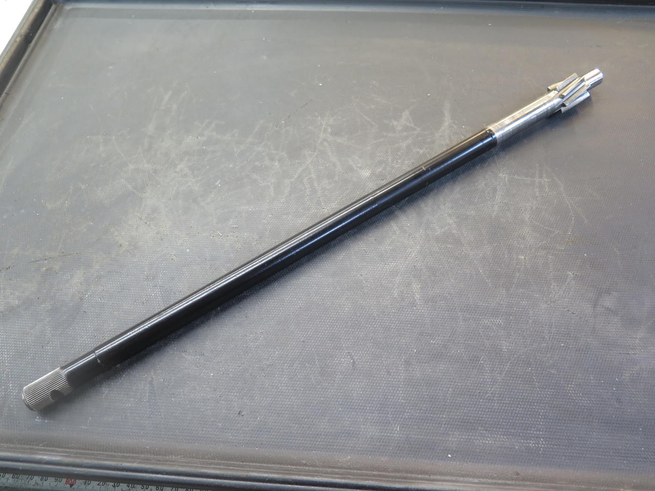
Then the pinion and the rack came out.
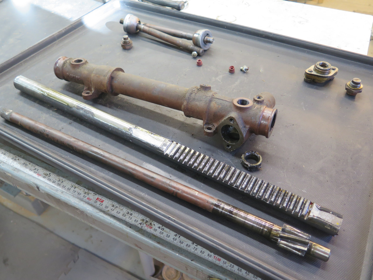
I prepped the housing for blasting, mainly by plugging openings to keep the grit out of the inside.
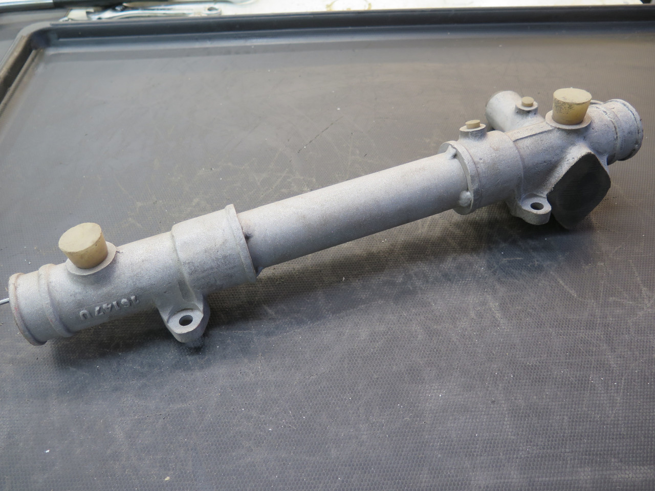
Then a nice powder coat.
Pinion shaft got the same treatment.
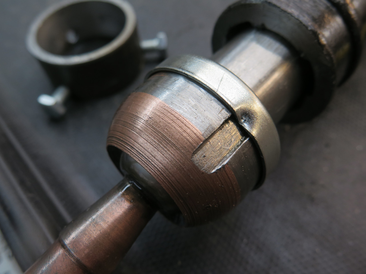
Then on to the tie rods. They have a ball and socket swivel joint
which allegedly can come apart. The joints on my tie rods were
both very smooth with no detectable free play, but as with most parts of
this overall project, I really wanted to get inside to see for myself
the condition of the guts anyway. Theoretically, they come apart
by using a pin spanner in the two holes on the back side to unscrew the
cap from the housing. The main challenge with this is how to hold
the housing stationary while doing that. There is apparently a
special factory tool for this, but I've never even seen a picture of one
let alone have one in my tool box.
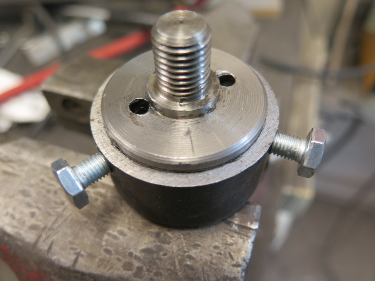
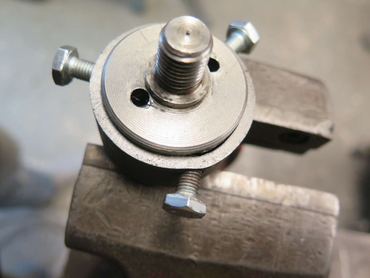
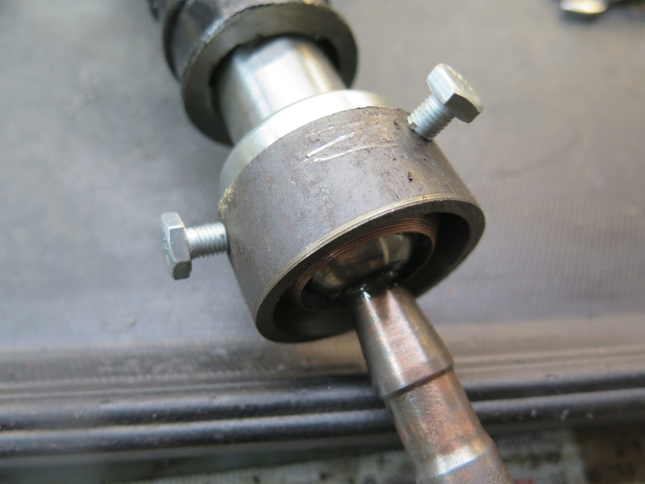
I did fashion a holder though, consisting of a steel ring with three
bolts threaded into it such that the ends of the bolts align with the
three slots in the joint housing. This would allow me to use all
manner of wrenches, vises, and other implements to hold the housing
fixed.
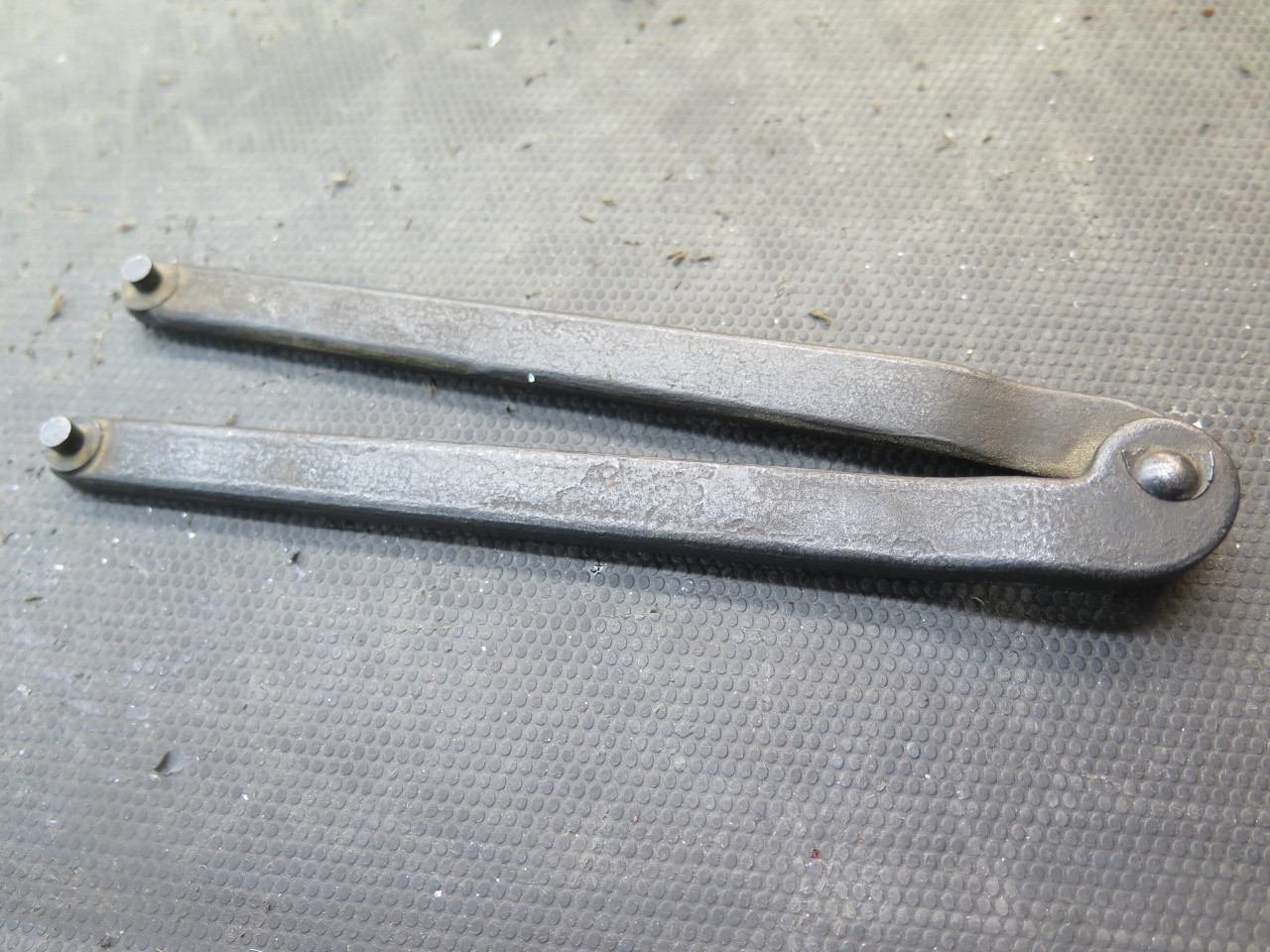
I did find in my tool box a suitable pin spanner, that with a little minor modification, fit the backside holes perfectly.
I approached the disassembly operation with great confidence. I
tugged. I pulled. I added a two foot cheater bar to the
spanner and tugged and pulled. The joint mocked me. I was
afraid I was close to breaking the spanner, but soldiered on, with some
applied heat. In the end, the spanner survived, but the ring was
just deforming.
Utterly demoralized, I paused to re-evaluate. I could make a
stronger ring and a longer cheater bar. But I knew the spanner
would probably fail.
In the end, I came to a reluctant peace with the defeat. After
all, there was no real reason the joint HAD to come apart, and I was in
danger ruining something.
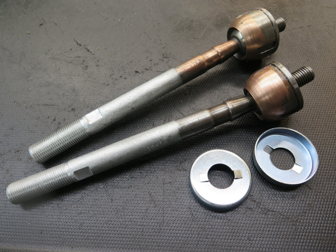
To take my mind off the resounding defeat, I cleaned the rods up, zinc
plated the parts that would be exposed to the elements, and flushed the
insides by pumping oil into the holes. And ordered new lock cups.

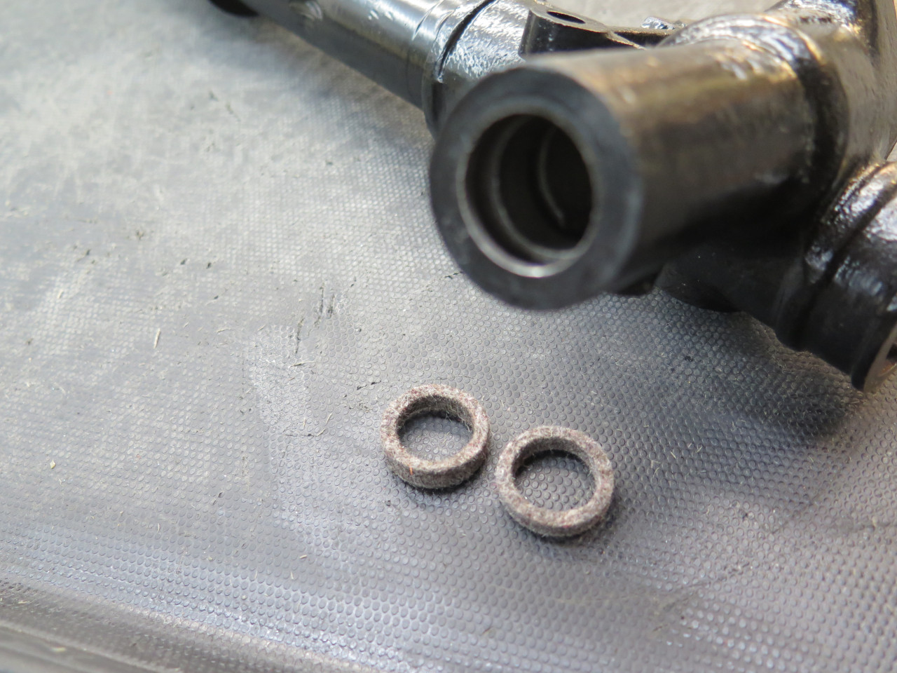
One last thing before reassembly was the seals for the pinion
shaft. These were a pair of felt seals from the factory, but in a
partial restoration I did to this car in the 70s, I'd replaced them with
O rings. That may not have been the best decision. For one
thing, the size of the gland (O ring speak for the groove) is
wrong. For another, the location probably doesn't get much ongoing
lubrication. The O rings I took out were clearly flattened on
their ID, due to wear. The felt seals would hold a reserve of oil.
So, I resolved to respect the designers' choice, and ordered the felt seals.
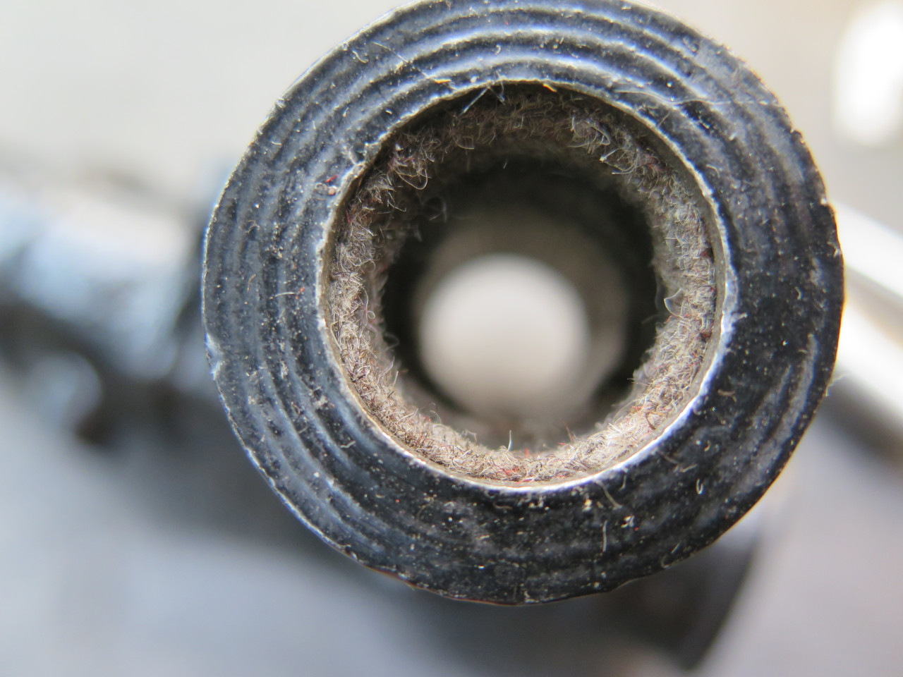
Saying that coaxing these seals into those grooves was a finicky chore
is an understatement. Especially the lower one. I installed
them dry, then saturated them with oil in place.
This allowed the rack and pinion shafts to go home. I feared that
the pinion shaft might dislodge the felt seals, but the generous chamfer
on the end of the shaft prevented that.
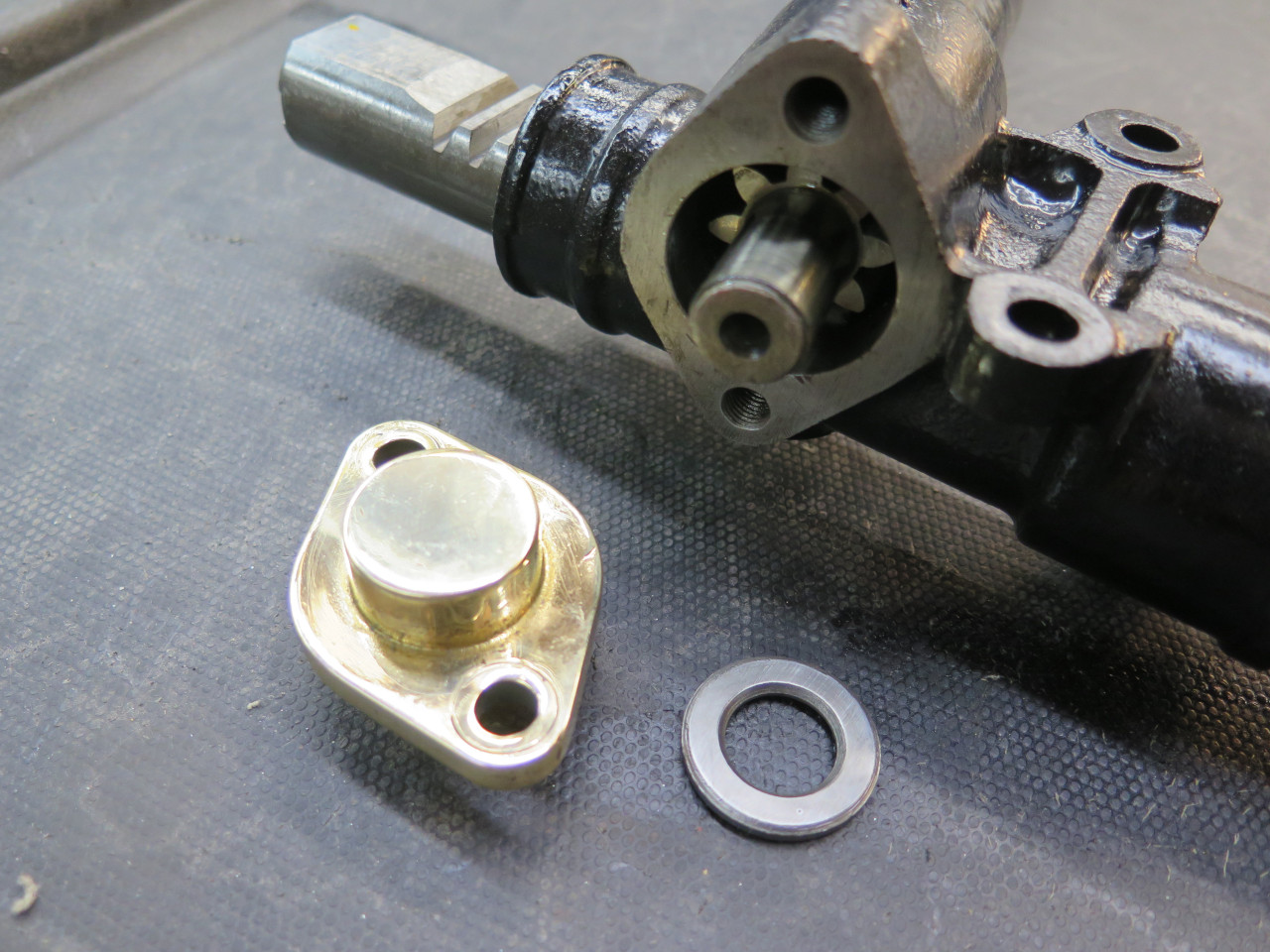
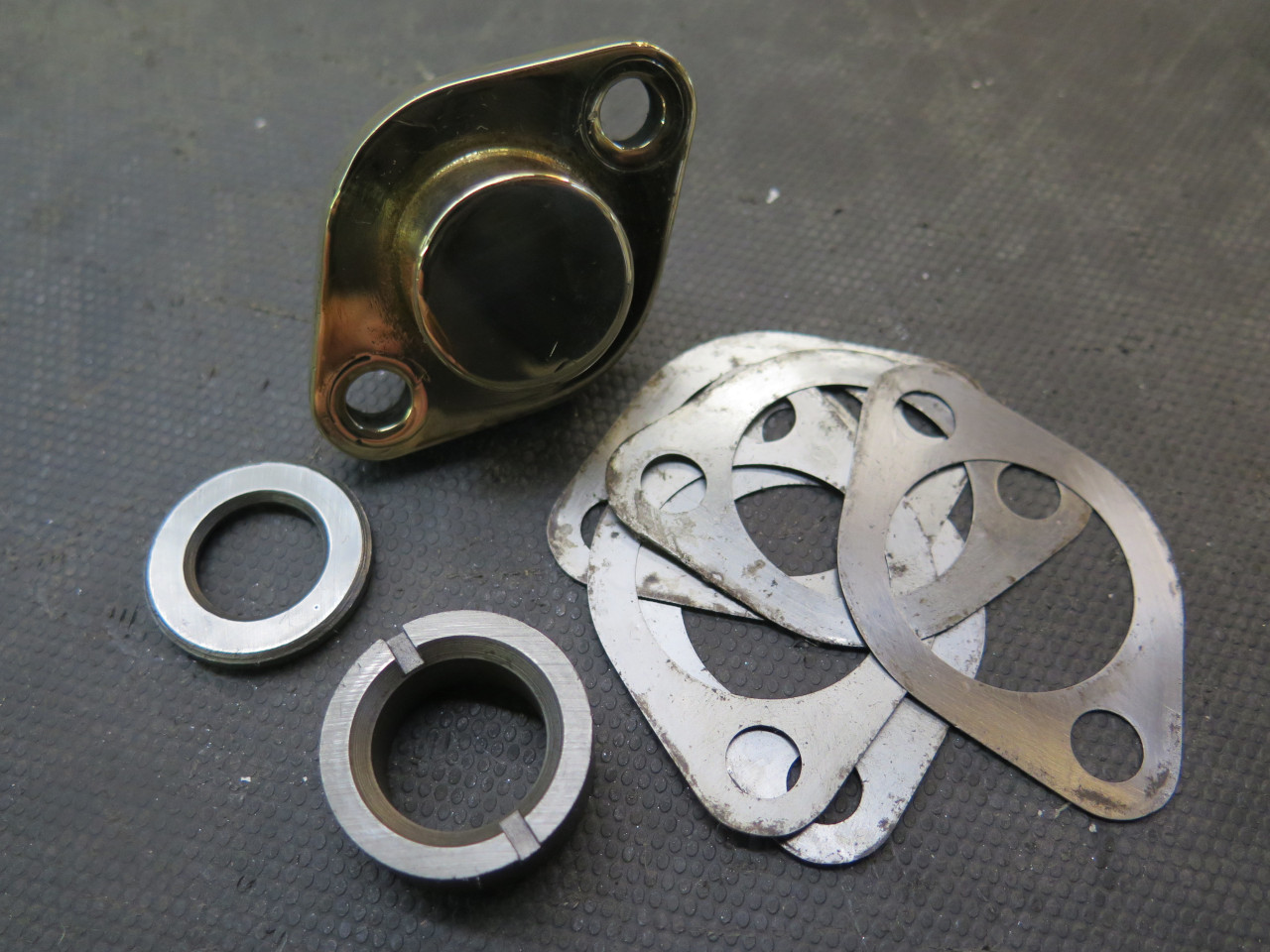
The chunky brass cap that supports the end of the pinion also sets its
end play. It does this by using shims under the cap mounting
flange. I snugged down the cap with no shims, and measured the gap
between the flange and the housing. Add around 0.003" for
clearance, and that's the total shim pack needed. I left out the
thinnest original shim (about 0.006") and buttoned everything up.
Pinion has a barely detectable end play.
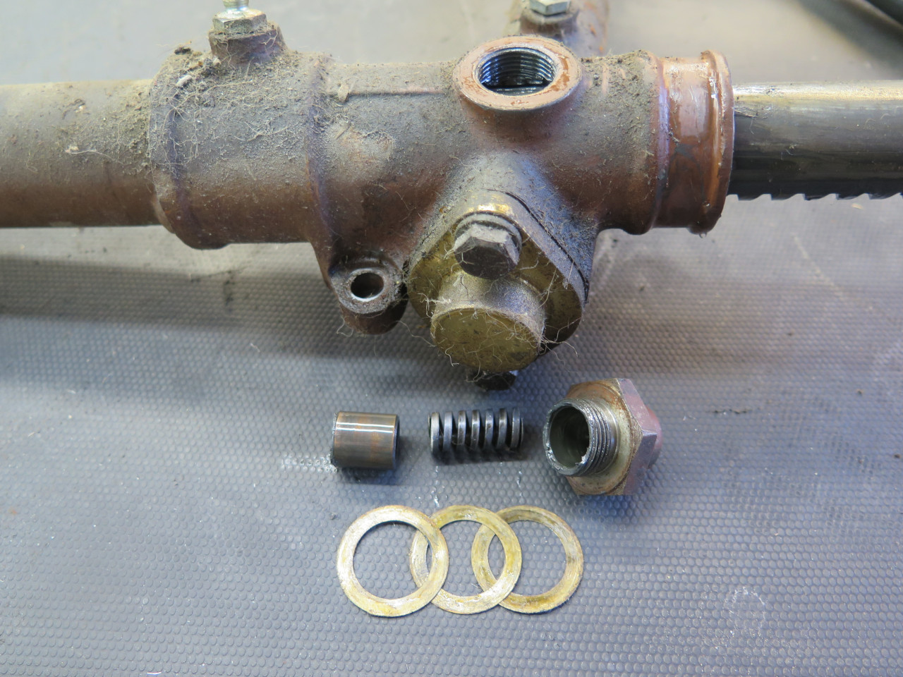
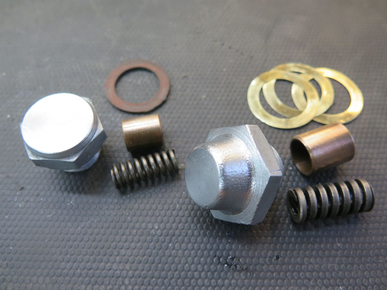
There are also a pair of damping devices in the main housing.
These are just spring loaded brass pistons that bear directly on the
rack. They intentionally increase friction that opposes rack
motion. This gives a more firm feel to the steering as well as reducing
the feedback from the road.
The caps weren't zinc plated, but I thought they should be.
The primary damper bears on the rack just opposite to where pinion teeth
engage with the rack teeth. Besides damping, this also biases the
rack toward the pinion, reducing play between rack and pinion
teeth. This damper is adjustable by shims, and should allow the
rack to just be drawn through the housing by hand.
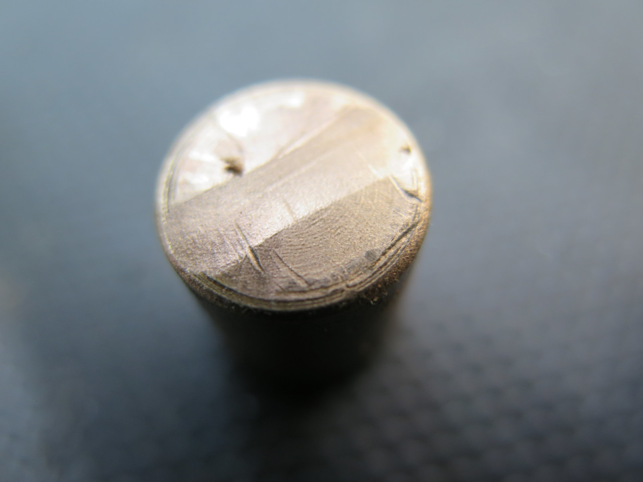
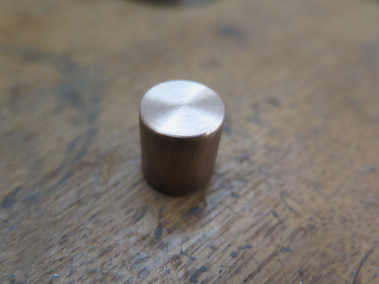
I noticed that the brass part that rubs on the rack had a furrow worn
into it. It seemed to me that this might affect the damping action
depending on its orientation with respect to the rack. A light
skim restored a nice flat surface.
I assembled the main damper and tightened the damper cap without shims
to the required resistance, then measured the gap between the cap and
housing boss. The required shim pack was essentially the same as
what I took out. The secondary damper is at the opposite end of
the housing, and doesn't require adjustment.
The tie rods were then re-attached to the rack using new lock
cups. My damaged ring tool still worked well enough to help seat
them tightly. The cup is then deformed into the grooves in the
ball housing to lock it in place.
Next up were the boots or gaiters that protect the ball joints. I
opted for the "premium" set, made from silicone rubber. I was a
little disappointed to find that they are actually a sort of "universal"
part, and that I could have bought them elsewhere for about half the
price.
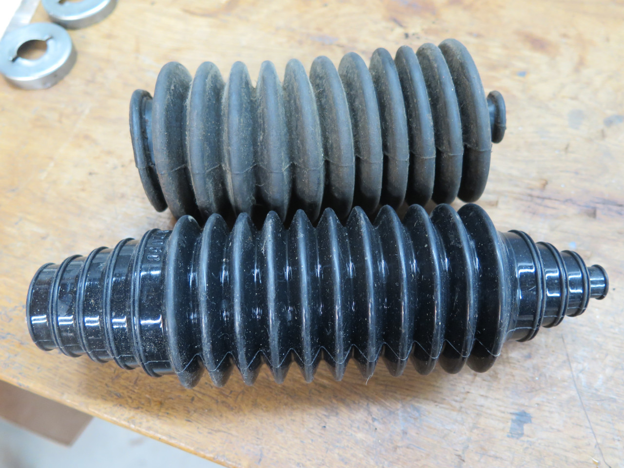
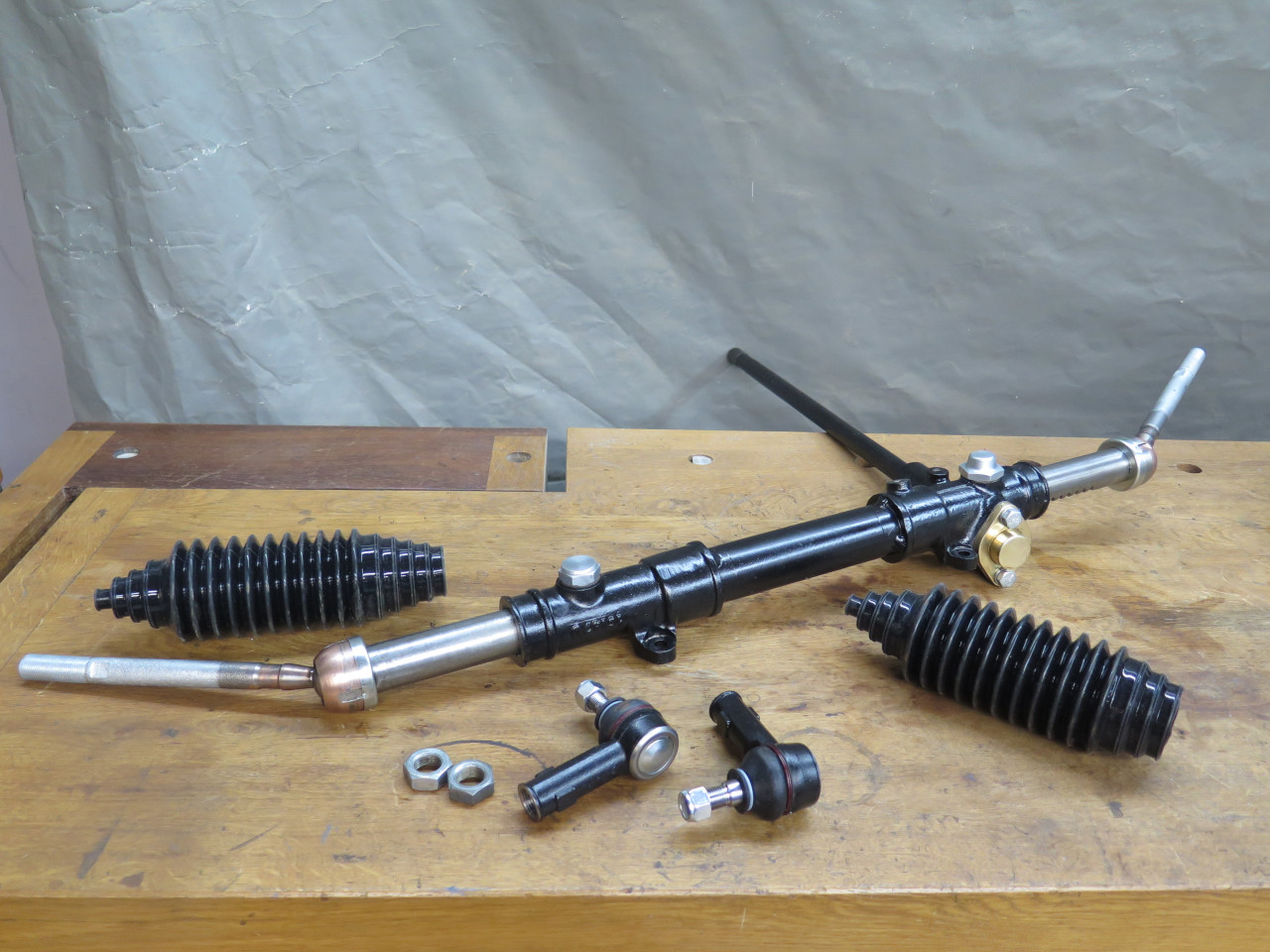
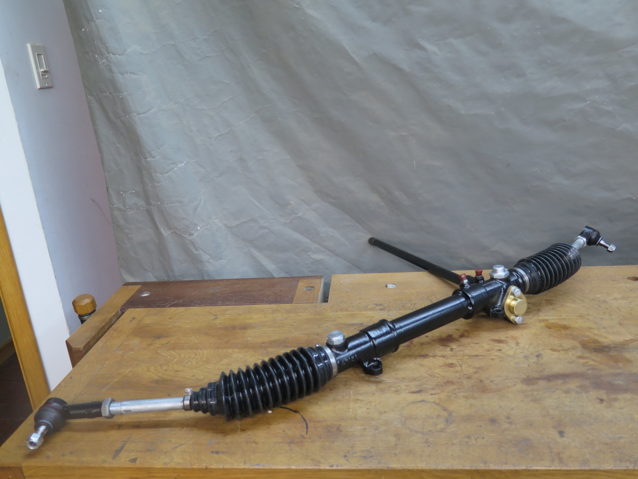
New tie rod ends, and we're about ready for final assembly.
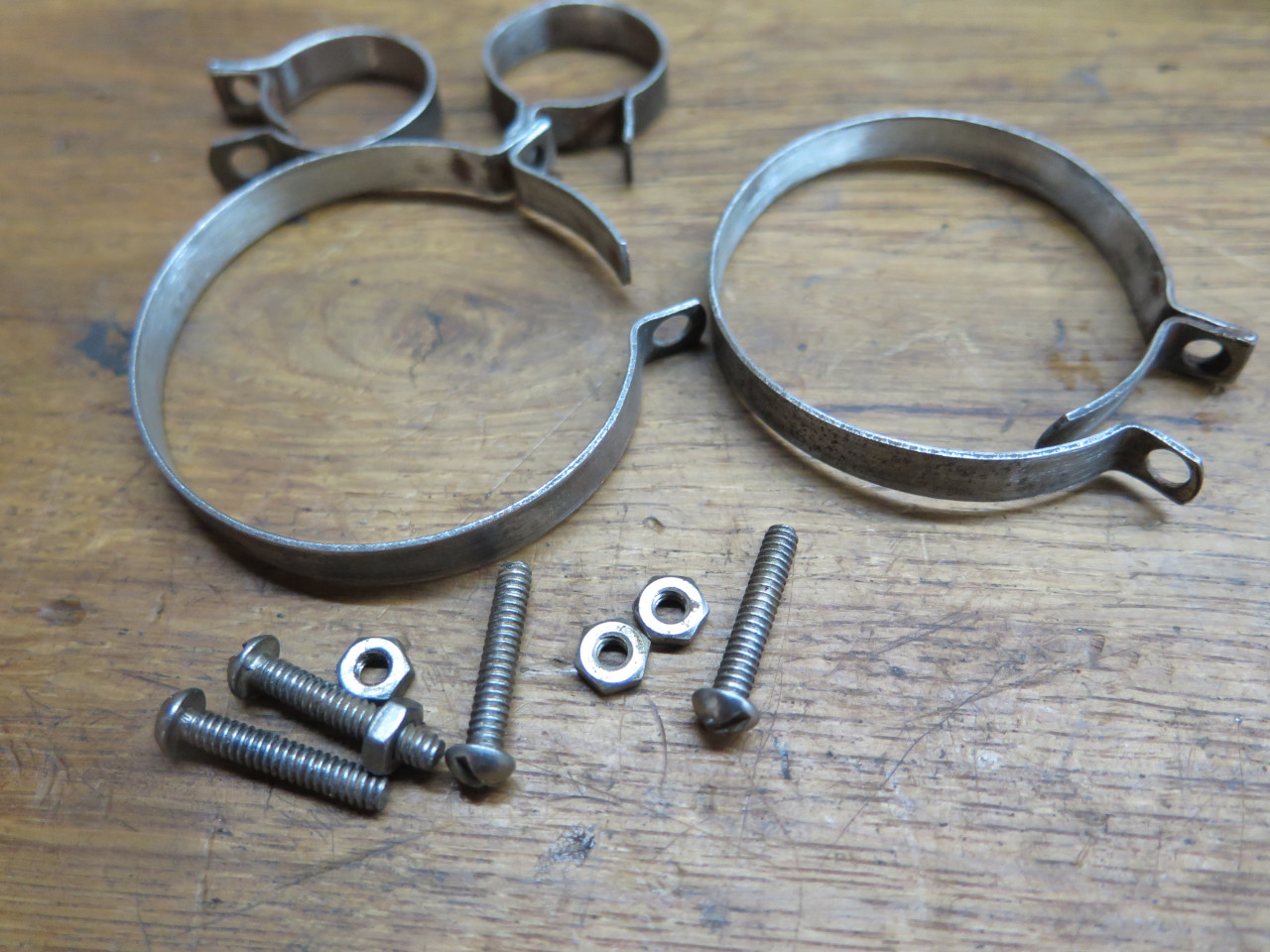
In another small disappointment, the new boots came with just zip ties
to fix them in place. I preferred to clean up and re-use the old
metal clamps.
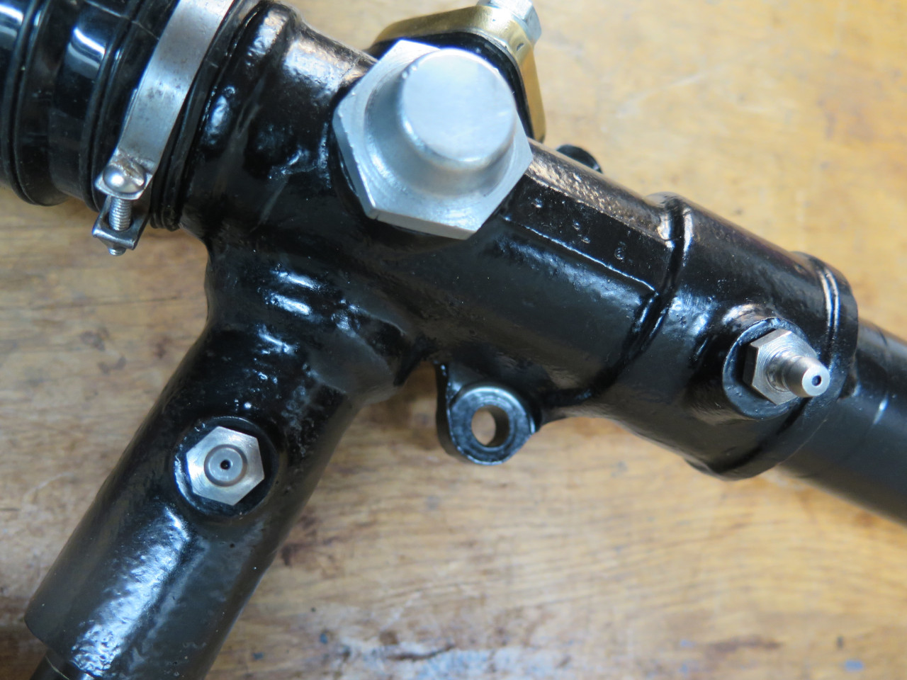
New Zerk fittings finish up the assembly.
Then just squirt in 8 ounces of 90 weight hypoid oil...
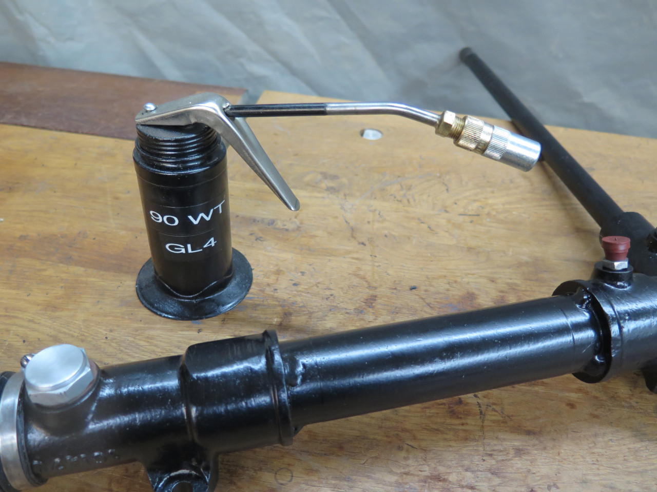
...and this puppy goes on the shelf until the frame is ready for it.
This was a nice project for the warm shop on cold winter days. Cost was probably less then $50.
Commnets to Ed at elhollin1@yahoo.com
To my other MGA pages