After getting used to it, though, I identified a couple of features I wish it had. First, I thought a way to feed the wire independent of the trigger would be nice. When loading a new spool, or just getting a little more stickout, it could be done without activating the gas or energizing the gun. Second, an independent gas feed would be handy for a couple of things: to purge the hose of air after a long period of non-use, and more interesting to me, as an easy source of dry inert gas for other uses, like displacing the air from paint or varnish containers when resealing them.
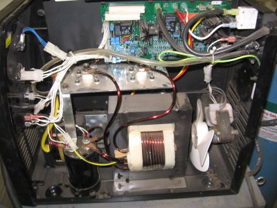
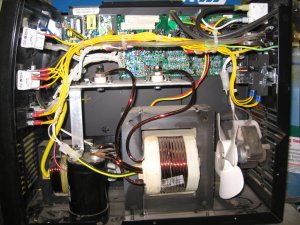
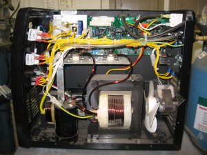
When modifying the welder, I didn't want to disrupt the wiring to the point of not being able to return it to stock condition, so I didn't cut or remove any existing wiring. Also, not having a schematic of the control board, I didn't want to change any voltages, currents, or loads that the board sees. To this end, I added a 220 VAC relay that the existing power switch controls. The relay in turn provides the contact closure to the control board in place of the power switch. This gave me switched 240 VAC to work with.
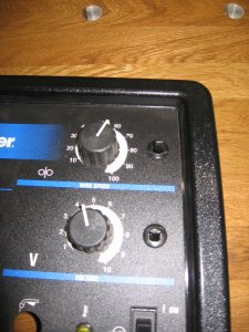
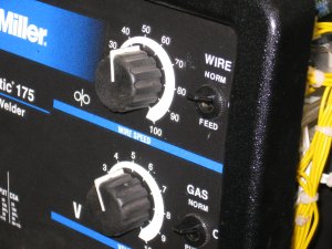
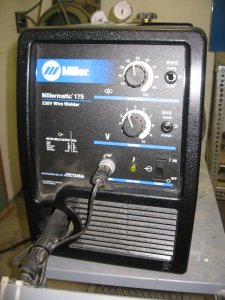
I added two switches to the front panel. Both are three-position DPDT switches with a center off and one side momentary. The momentary side was for wire or gas feed, with the other on position for normal operation.
Power for the momentary wire feed was fed through the switch from a small 240 VAC-12 VDC power supply I added. This relieved me of figuring out how to turn on the control board's motor supply. The gas valve is 240 VAC, so it was fed directly through the momentary side of the gas switch. I ended up wiring the power for the gas feed on the hot side of the power switch so the welder doesn't have to be on to get a shot of gas.
Here are some pictures, Click them to expand.
