October, 2012
Rocker Spindle Oil Grooves
[Click on pics for a better view]
It
seems pretty well established in Triumph lore that long about the
late 60s, there was a bit of a mixup in a redesign of valve trains.
Prior to the redesign, rocker arms were drilled to route oil to
the pushrod tips, but there wasn't any explicit provision for
lubricating the valve adjuster tips. The design change involved
eliminating the rocker arm drilling, and instead grinding a small slot
in each end of the rocker to direct oil to those two critical areas.
The new design also involved a change in the order of assembly
some of the washers on the rocker spindle to make sure the oil went
where it was needed. This is the source of the well documented
"Thackeray Unpleasantness", wherein some shop manuals took a while to
catch up with the new direction, and some bikes even reportedly got
assembled incorrectly at the factory.
What
is a little less clear about the whole sordid affair is whether oil
grooves on the rocker shafts were another another element that got lost
in the confusion. Some models apparently did get oil grooves with
the other changes, but others didn't, at least until later model years.
My '71 Daytona didn't have them, and it is reported that the the
T100s never got them.
Here is one of my 42-year old spindles:
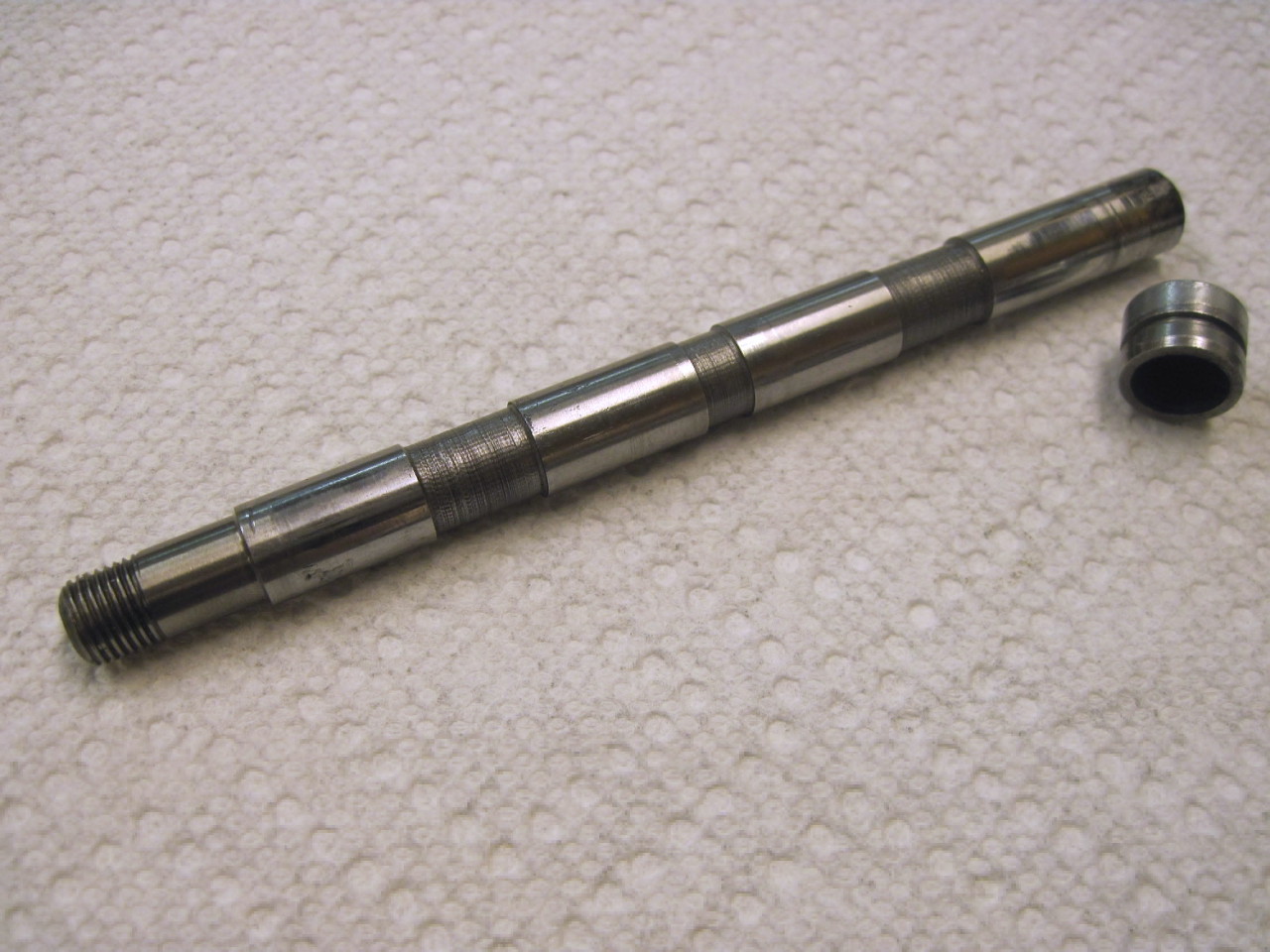
The
worrisome thing is that the newly supplied lubrication slots in the
ends of the rocker arms were fed by whatever oil migrates through the
annular space between the rocker and the spindle, which could be as
skinny as 0.00075 inch in a new bike. Couple this with the
relatively low oil pressure reaching the rocker boxes, and it makes a
guy wonder if grooves were intended for the new design, but fell
through the cracks along with the washer placement. Some very
knowledgeable people on some Triumph forums have wondered the same
thing.
At
any rate, it was keeping me from sleeping at night, so I finally
decided to fix it. I looked at spindles from other models that
did have the grooves, and got some dimensions to go by. I have a
little manual milling machine, and after some pretty intense fixturing,
I had a setup that I thought would do the job.
One
of the reasons this took so long to do is that I already had the engine
buttoned up and in the frame, and didn't relish the idea of trearing
into it again, even if it was just the rocker boxes. Even though
I was advised that it probably wouldn't work, I decided to try to
remove and replace the spindles without taking the boxes off. It
ended up working out fine, using the two simple little tools shown.
The bottom one is the same diameter as the threaded part of the
spindle, and has a little protrusion on the end that fits in the hole
in the end of the spindle. I used this as a drift to push the
spindle out, and left it in place so that everything would stay in
place and nothing could fall out.
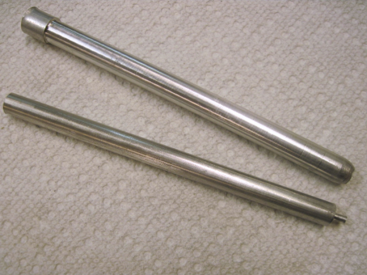
When
a spindle was ready to go back in, I used the second tool to push the
first one out. The second tool is just slightly smaller than the
spindle itself, and has a tapered end. This aligns anything that
might have shifted. Then the smaller shaft again carefully pushes
the big one out, and then guides the spindle back into place.
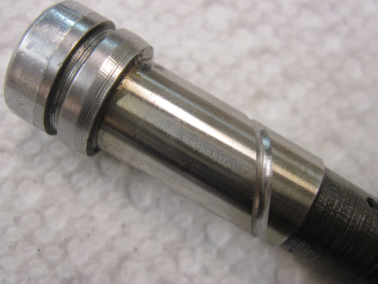
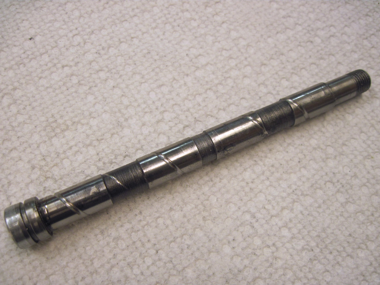
Here are the grooved spindles.

It was a challenging and interesting project, but was it necessary? Who knows, but I am sleeping better.
Comments? elhollin1@yahoo.com
To other pages.