U Joint Math 101
Automotive
drive shafts typically consist of a driving flange that couples to the
gearbox output shaft, an intermediate shaft, often with a sliding
coupling, and a driven flange that connects to the differential
pinion shaft. At the intersections of the driving flange and the
intermediate shaft, and also the intermediate shaft and the driven
flange is usually found a cardan joint, more commonly called a
"universal joint" or U-joint. It is the universal joint's job to
deliver rotation across the joint even when the two sides are at an
angle to each other.
The U joint consists of a yoke on both
sides connected with a cross-shaped piece. Two opposing ends of
the cross have bearings that fit into the yoke arms of one shaft, while
the other two cross ends connect similarly to the other shaft yoke.
The cross allows rotation across an angle by rocking back and
forth inside the joint.
Though the basic function of a U joint
is fairly simple to grasp just by playing with one, there are some
nuances that aren't apparent. The primary one is that the rotary
motion is not transmitted across the U-joint uniformly. This is
not a secret, and is certainly old news among car people, but it's not
often that the math behind the concept is shown. While not that
easy to visualize, the derivation of the relationship between input and
output motion just uses highschool trig and algebra.
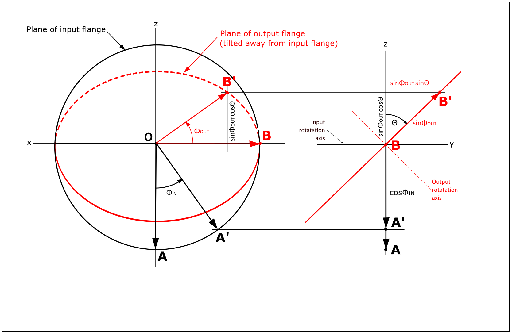
The
diagram shows a schematic rendering of a U-joint. The black
circle represents the path of points on the rim of the driving, or
input flange of the joint. It is viewed directly inline with its
axis.
The red ellipse is similar for the driven, or output
flange. Since it is at an angle Θ to the input (driving) flange,
it is tilted back and appears as an ellipse from this viewpoint.
To the right of the circles is a side view of the schematic
joint, showing the flanges edge-on. and clearly showing the angle Θ
between them.
Also on the drawing are vectors OA and OB.
Point A represents one of the yoke arms on the input flange while
point B is one of the yoke arms on the output flange. They are 90
degrees apart. As the joint turns, the black vector OA traces the black
circle, and the red vector OB traces the red circle (which looks like
an ellipse in thie view), but the two vectors are always constrained to
be at right angles to each other. Note that in the position shown
for vectors OA and OB, they are both in the "black" plane, since point
B is on the line where the two planes intersect.
Now, if we rotate the input flange through angle ΦIN,
we arive at the situation shown by the vectors OA' and OB'. Point
A' is on the black circle, but point B' is now "behind" the black plane
on the red circle. OA' and OB' are still at right angles to each
other, though it may not look so because one of the vectors is out of
the plane of the picture. The rotation of the red vector on
its red circle is ΦOUT.
At
this arbitrary position of the vectors, we can start to characterize
their positions. To simplify the notation, we assume both vectors
are unit vectors (length=1).
The projected length of the red vector in the side view is sinΦOUT, and this can be used to get the y and z coordinates of the point B' as shown.
Gathering the remaining coordinates of the ends of the two vectors, we have:
A' = (sinΦIN , 0 , -cosΦIN), and
B' = (cosΦOUT , sinΦOUTsinΘ , cosΦOUTcosΘ)
Next,
we invoke the requirement that the angle between vectors A' and B' be
right. We do this by deriving an expression for the 3D distance
between A' and B', and setting it equal to √2 (since the hypotenuse of
two unit vectors at right angles is √2).
The result is a fairly gnarly trig expression that reduces to:
tanΦ
OUT = tanΦIN/cosΘ.
As
a sanity check, we look at how the input and output angles are related
for a couple of special values of Θ. At Θ=0 (no angle between the
input and output), cosΘ = 1 and tanΦOUT = tanΦIN, or ΦOUT = ΦIN, just what we'd expect. With Θ = 90°, cosΘ = 0, and we get no rotation (no rotation around the output flange's axis, that is).
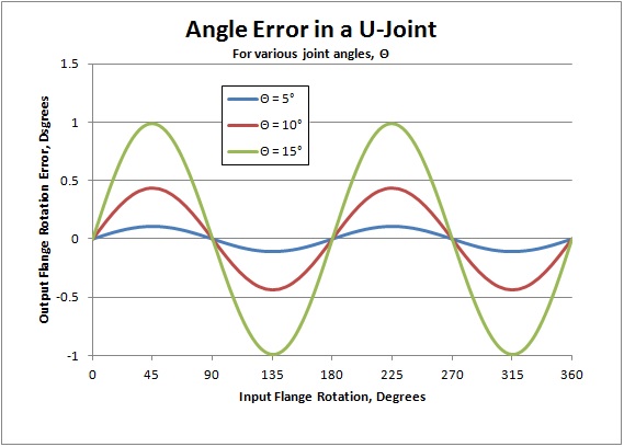
So
what does this mean? It means that for every revolution of the
input flange the output flange alternates between leading and lagging
the rotation of the input at a frequency of double the rotation speed.
Graphing the relation shows that for a 15 degree joint angle, the
rotation error will be +/- about 1 degree.
While
this illustrates the problem with single U joints, it is even more
instructive to look at the rotational speed. (or RPM for car folk).
It should be apparent that when the output flange is
transitioning from a lagging angle condition to a leading one, it will
have to be turning faster than the input flange, and slower for the
lead to lag situation.
If we take the time derivative of the angle expression, we get an expression for angular velocity (or RPM for car folk).
In this analysis, we will assume that Θ doesn't vary with time, so cosΘ is a constant.
dtanΦOUT/dt = dtanΦIN / cosΘ dt
sec2ΦOUT dΦOUT/dt = sec2ΦIN / cosΘ dΦIN/dt
But dΦOUT/dt and dΦIN/dt are just angular velocities, so we'll rename them ωIN and ωOUT.
ωOUT/ωIN = sec2ΦIN / (sec2ΦOUT cosΘ) .
Through some trig manipulation and eliminating ΦOUT, we get
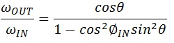 .
.
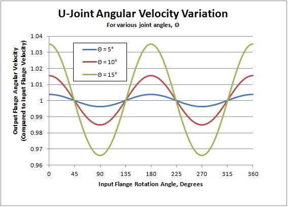
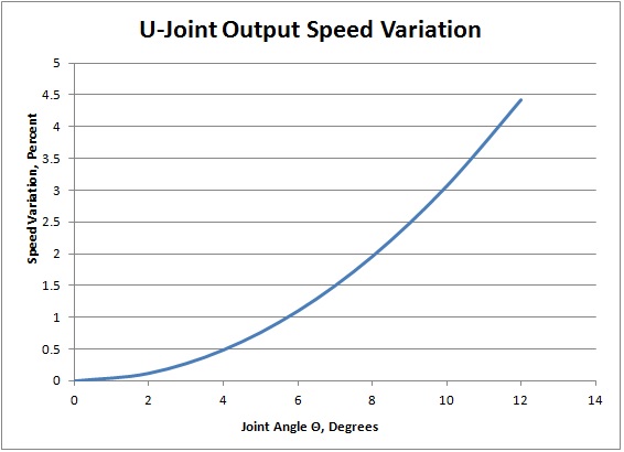
Graphing
this relation shows how the output flange speed (e.g. RPM) varies
during a revolution of the input flange for various joint angles.
When the angle error is moving from lagging (negative) to leading
(positive), the velocity is necessarily higher. The range of this speed variation from minimum to maximum is given by
ωIN (1/cosΘ - cosΘ).
Graphing this relationship shows that the variation grows at a faster rate for larger angles.
This
is of course why single U-joints are never used where speed or angle
distortion can't be tolerated. In practice, U-joints are always
used in pairs for automotive applications, arranged such that the
second joint exactly cancels the distortion introduced by the first one.
If
the joint schematic illustration above is duplicated, but with all
vectors rotated 90° counterclockwise, the angle equation then becomes
tanΦOUT = tanΦIN * cosΘ.
It
should be obvious that applying one equation after the other, with the
output of the first joint becoming the input of the second one, the
cosine terms cancel, leaving tanΦOUT = tanΦIN, and ΦOUT = ΦIN. In turn, this also makes the speed variation disappear.
There are two major caveats in this perfect error cancelation, though.
First, the "phasing" of the joints must be correct. The driving (input) yoke of the second joint must be rotated 90° from
the driving yoke of the first joint. If it is not in this
orientation, the cosΘ terms don't cancel--they multiply, giving an
overall function
tanΦOUT = tanΦIN/cos2Θ.
This
effectively doubles the angle and speed distortion rather than
canceling them. In a typical drive shaft, it is often pretty easy
to assemble the parts with incorrect joint phase, leading to driveline
vibration due to the speed variation.The
second caveat has to do with an assumption we made when we added the
second U joint. We assumed that the joint angle Θ was the same
for both joints, and this is true only under certain
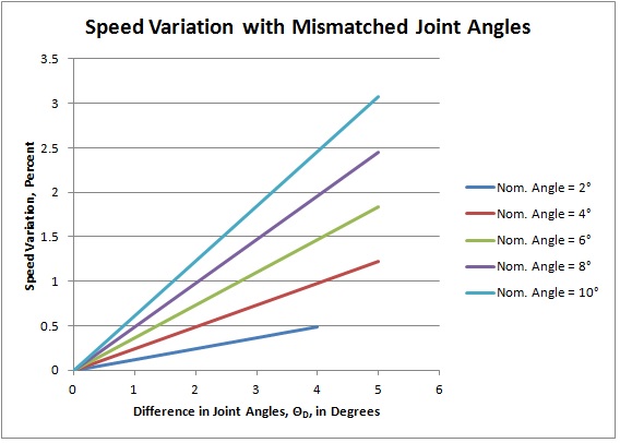
conditions. If the two joint angles are different,
cancellation will be imperfect, and some speed distortion will
remain. The effective relation is
tanΦOUT = tanΦIN * (cosΘ1 / cosΘ2),
where Θ1 and Θ2 are the joint angles of the two joints.
If we identify ΘN, the "nominal" angle of the center shaft as the average of the two joint angles, and ΘD as the difference between them, the graph below shows how speed variance is affected by angle mismatch.
This
should be convincing evidence that the two joint angles must be equal
to get perfect cancellation of angle and speed distortion, but what does that mean on a practical level?
It
basically invokes the basic axiom of geometry that a straight line
crossing two parallel lines will cross them at equal angles. This
means that if the axis of the input flange of a drive shaft is parallel
with the axis of the output flange, the angles of the two U joints will
be equal. This in turn implies that the axis of the gearbox
output shaft must be parallel to the axis of the pinion shaft of the differential.
The two axes can certainly be offset (it's sort of a drive
shaft's job to accommodate this), but they have to be parallel for perfect cancellation.
Any deviation from parallel will introduce some speed distortion
at the rear end, which could be felt as driveline vibration.
.