December 12, 2012
Pneumatic Power Drawbar for a Knee Mill
Earlier
this year, I got a new (to me) vertical milling machine. I love
the machine, and learn something every time I use it. One of the
things I learned early on was that I'm not tall enough. The
machine is almost 7-1/2 feet tall, and the drawbar hex is at just short
of seven feet. I can reach the drawbar, but I can't see it at the
same time. Though I've gotten pretty good at getting a wrench on
it by feel, I still have to feel around up there to free and draw up
the collets. I'd seen some examples of power draw bars on the
web, both commercial and home-brew. A DIY power draw bar seemed
like a good project to use the mill for, so I started formulating a
plan.
Most if not all of the DIY and power drawbars I saw were
based on pneumatic impact drivers. Most also used
pneumatic cylinders to lower the driver onto the drawbar hex and to
actuate the driver. I thought the air driver was a great way to
go, but I eventually favored a manual mechanism for lowering and
controlling the impact driver. I wasn't afraid of designing the
pneumatic control, but felt that I'd get a better feel for engagement
with a mechanical linkage. In some ways, the linkage for the manual
approach was more challenging.
I'll show the finished device in place first so some ofthe later pics will make more sense:
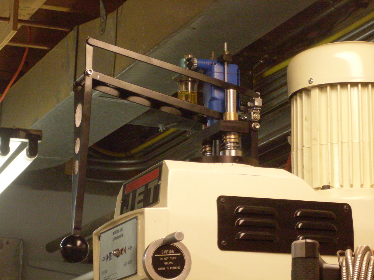
The
power drawbar is actuated using the ball handle that hangs down to a
comfortable height. There is a sort of dual-action parallelogram
linkage that lowers the driver when the ball is pulled straight down,
and actuates it forward or reverse when the ball handle is pushed
forward or pulled back. It is easy to feel the engagement of the
driver with the drawbar hex, and the actuating action is tight and
immediate.
Here's an outline on how it was done.
I
roughed out and then finished most of the parts from 1/2" and 3/4" 6061
aluminum. I've been playing around with anodizing lately, so I
also anodized them black.
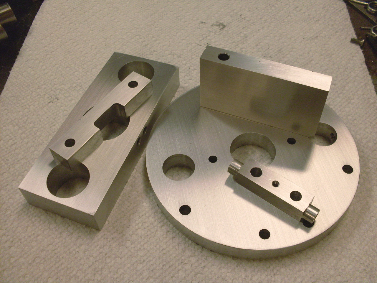
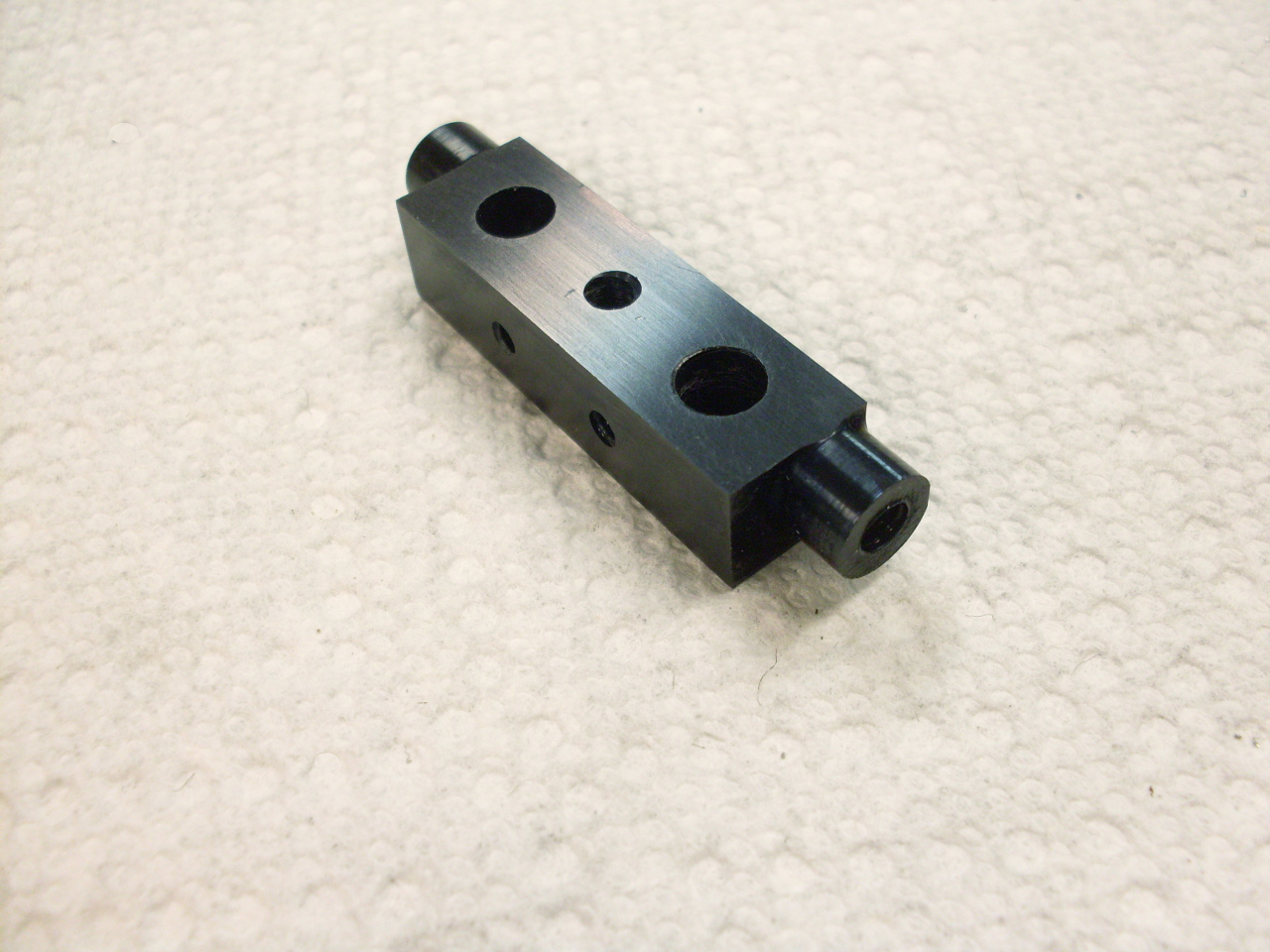
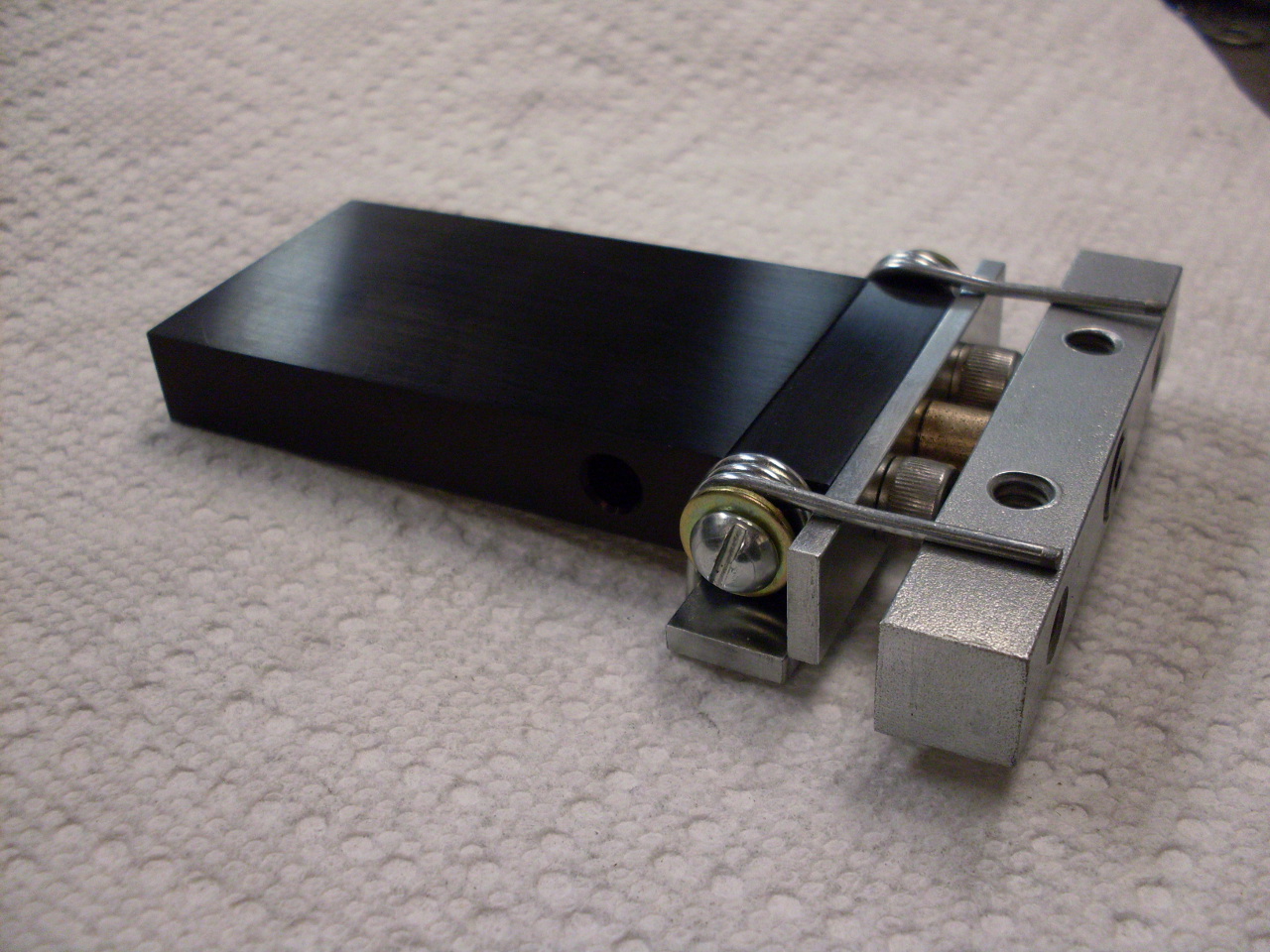
This
is a post at the back of the unit that carries the actuator arm
mechanism. The piece of 1/2" key stock is the actuator arm for
the impact driver and can pivot on a shoulder bolt fixed to the post
assembly. The springs allow it to pivot either way, but return it
to the central position. The two 1/2 x 1/8 steel pieces act as
stops for the springs.


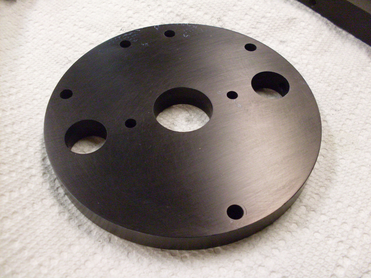
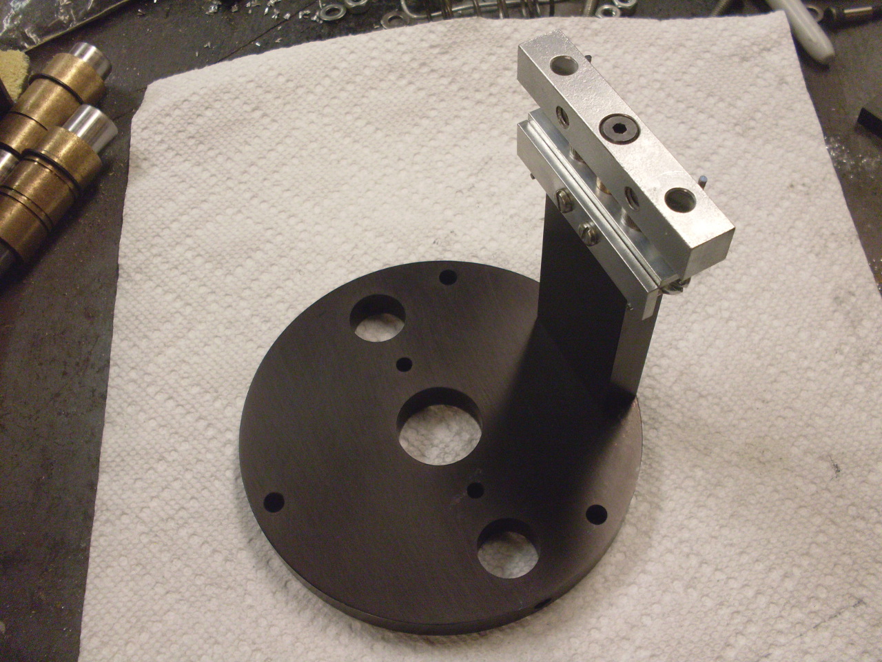
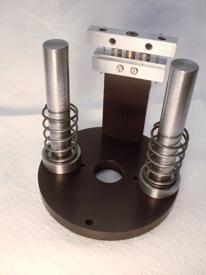
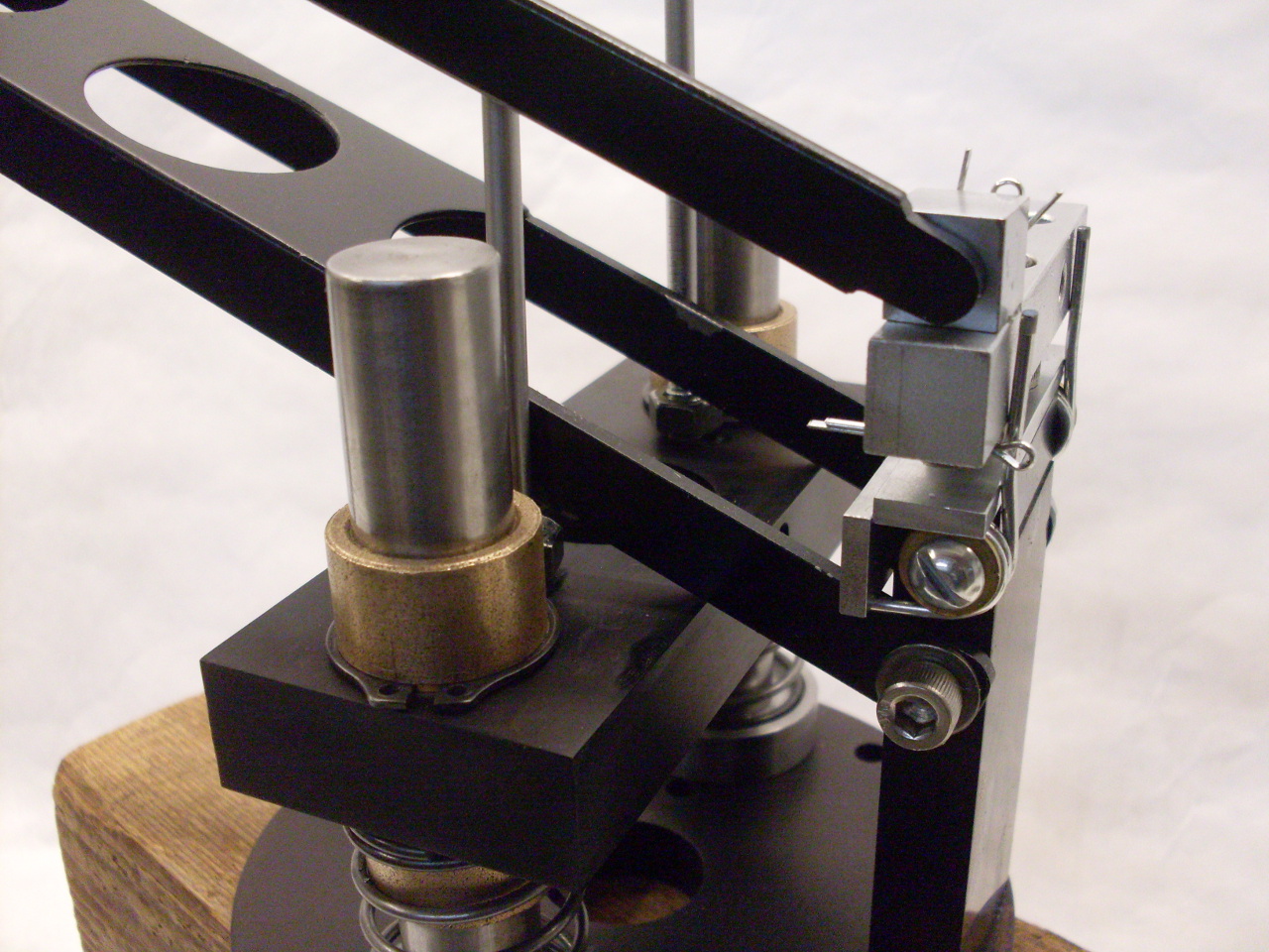
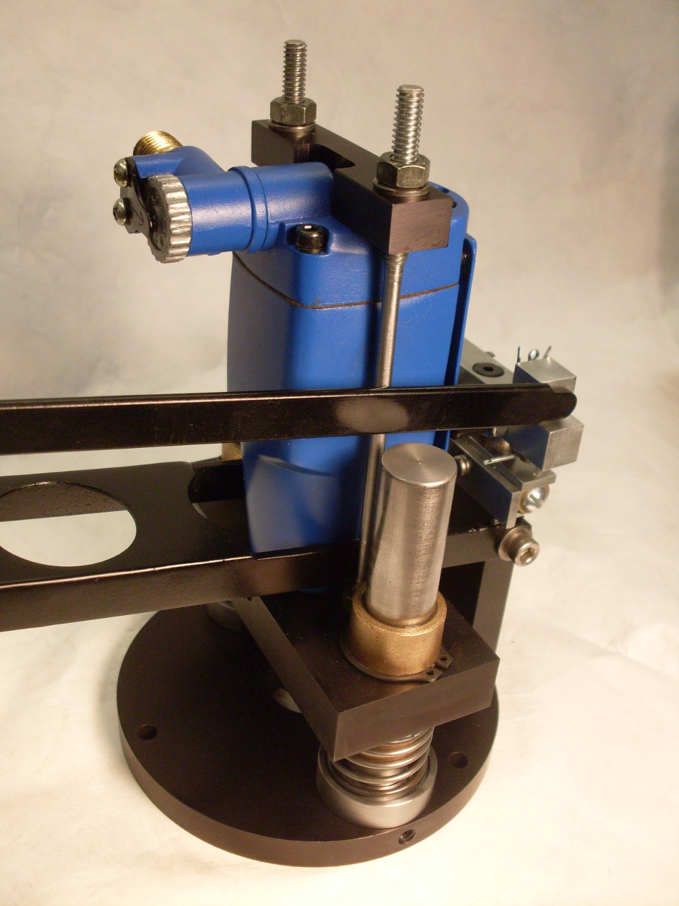
Here is the back post mounted to the base. Two chunks of 3/4" drill rod serve as slides for the impact driver carrier.
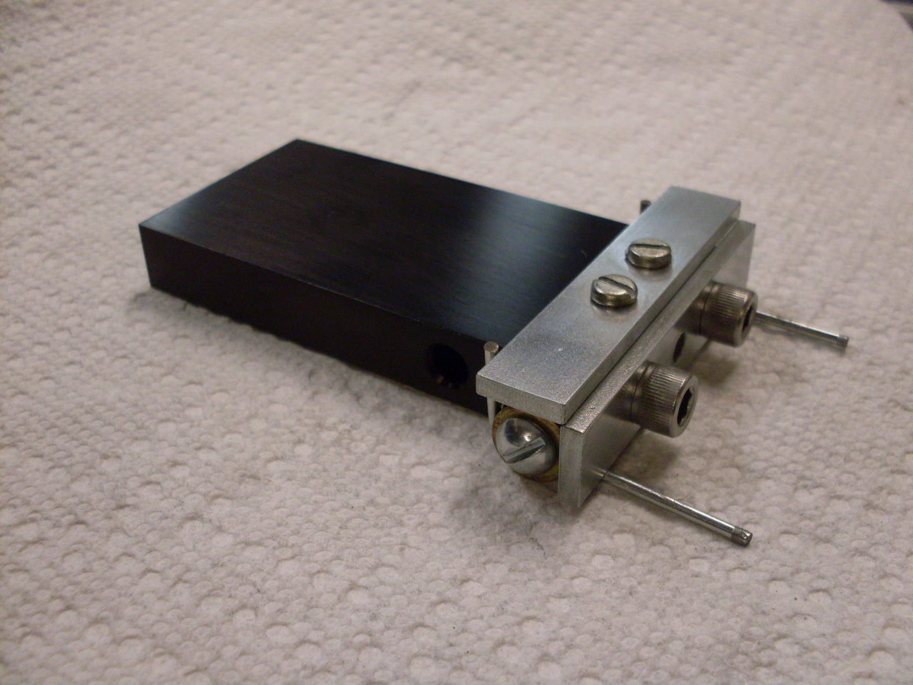
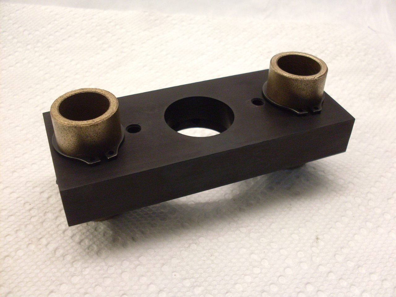
The
driver carrier is a piece of 3/4" aluminum bored to accept two oilite
bushings to ride on the slides. The thin rods are to hold the
driver in the carrier.


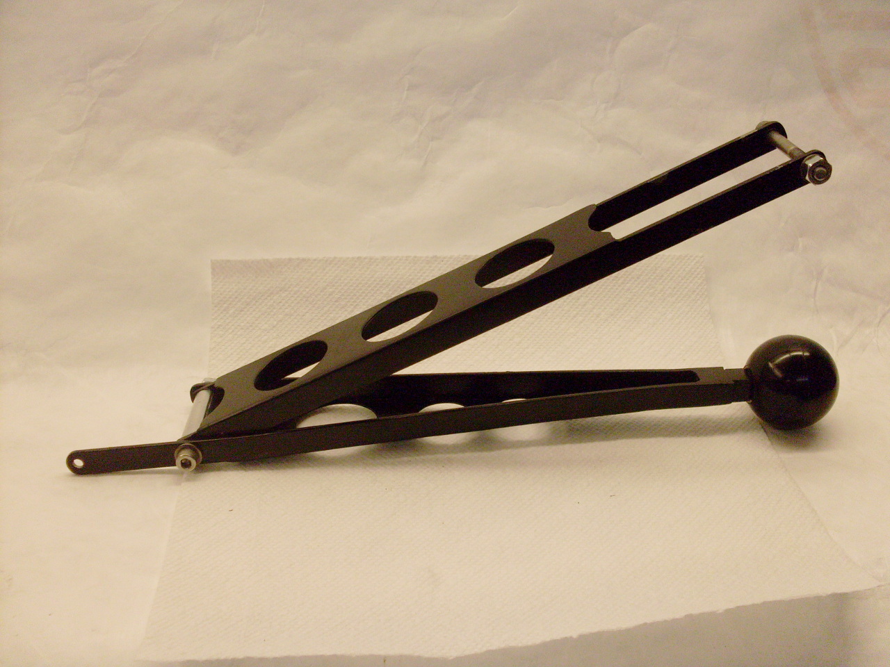
This is part of the control handle and linkage. It is just welded up steel painted black.
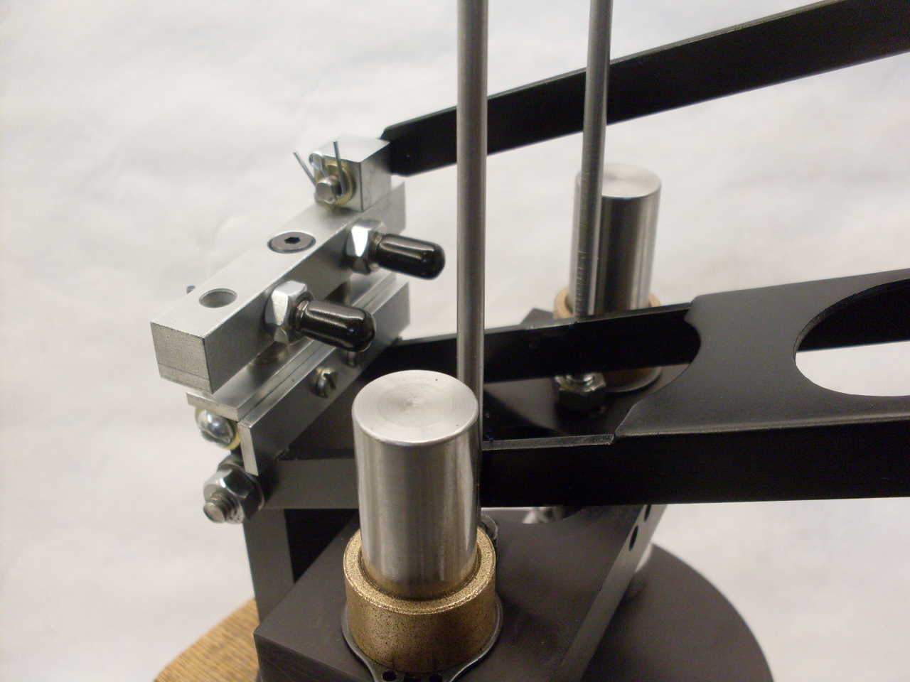
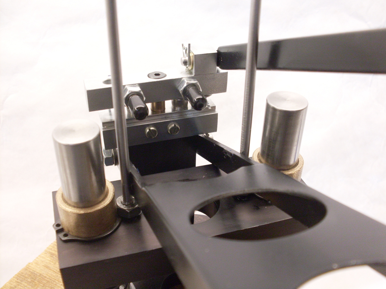
The
linkage connects to the actuator arm with that little universal joint.
It's a little hard to see, but the lower arm of the
parallelogram linkage bears on those two hex nuts to push the carrier
down. The little rubber caps are on some adjustable studs, and
push against the actuator paddle on the impact driver.

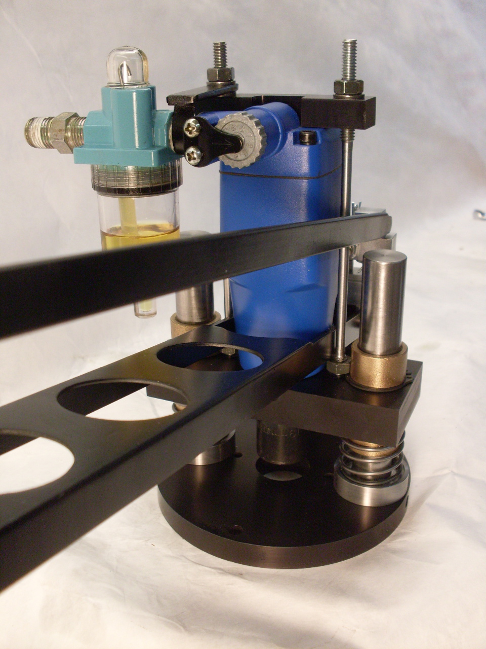
This is a keeper machined to fit the top of the impact driver.

I added a miniature inline oiler since doing it by hand would be a royal pain.

I
set the built-in "torque adjuster" on the driver to be wide open, and
control torque with a dedicated pressure regulator on the wall behind
the mill. Seems to work great. The only problem now is that
it is now even trickier to do the drawbar by hand, and I've got at
least one leak somewhere on my compressor, so I can't leave it
pressurized all the time, and have to charge it up every time I
want to use the mill.
Comments to: elhollin1@yahoo.com