August, 2010
I've
done some electroplating--mainly zinc and copper and a little bit of
nickel. I've made do with a little 1-amp variable power supply I
built probably 30 years ago. It works fine for small parts, but
for larger parts, it just doesn't have the juice to do the job.
Also, I wanted to try aluminum anodizing, and this process can
take higher voltages than my supply could manage. Considering all
this, I decided to build a larger variable supply.
Now
for serious plating or anodizing, many people recommend a variable
constant current supply. (Sounds like an oxymoron, doesn't it?
It just means that when you adjust it, you are setting the
current, and once set, the supply maintains that current over a range
of loads.) An adjustable constant current supply of the size
I needed is not a trivial design exercize, and while I probably have
the skills to do it, I was really looking for something I could get
into service quicker.
Even
an adjustable voltage supply of this size (0-30 volts @ 15 Amps) is not
a snap to design from scratch, so I headed down a simpler path. I
decided to build a simple fixed voltage linear supply, and then feed it
with a variable AC voltage. This is not a new idea, and seemed to
be the simplest and quickest approach.
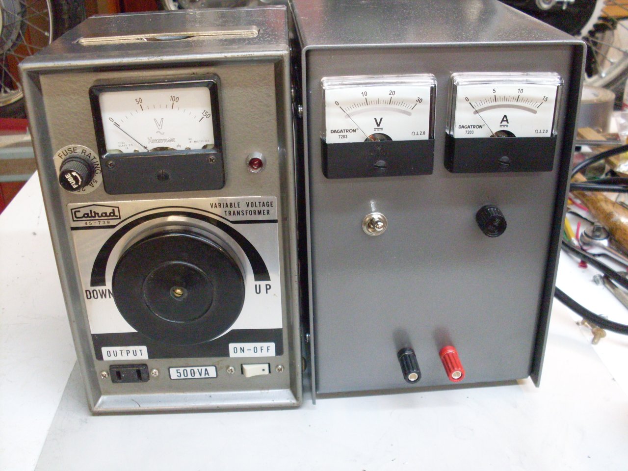
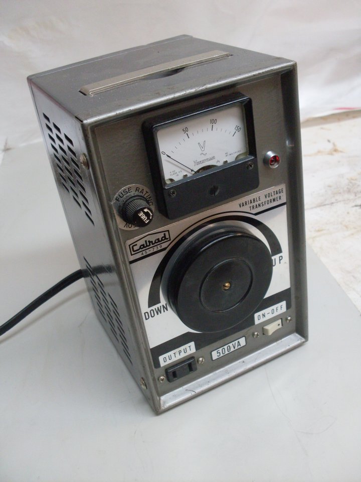
A
variable AC voltage is easily accomplished by using a variable
autotransformer, often generically called a Variac. I didn't have
one, but Ebay had many, and soon I had one of theirs for around $30.
It was an old used Calrad unit, reportedly in good working order,
rated at 500 VA--just about right for my needs.
The
unit was weighty, like a lot of older stuff, but the dial seemed to
bind on part of its rotation. Fearing the worst, I opened it up.
I found that the heavy transformer unit had shifted forcefully
enough, probably in shipping, to break one of its locating tabs, and
bend another. This put the core off center, bending the power
switch, and making the shaft bind.
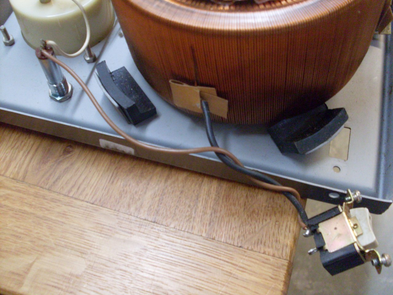
I fixed this pretty easily, and got the mechanism working smoothly.
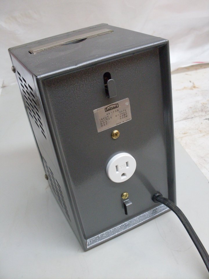
My
only other gripe with the unit is that, being of a certain age, it did
not have a 3-prong grounded power cord or recepticle. I fixed
that while I had it open.
I buttoned it back up, and it worked fine.
So mucdh for the variable AC source. Now to the linear AC-DC conversion.
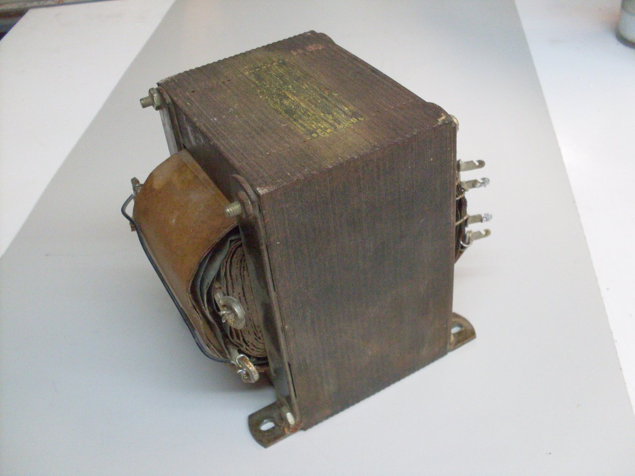
This
20+ pound bad boy is a Stancor 2012 power transformer, probably made in
the 1960s. It was in an old rack mnount power supply that I found
in the closet of an apartment I rented a long time ago. I've been
moving it for decades. The transformer is a universal type, with
a lot of winding taps to give a wide range of secondary voltages.
I was able to find a data sheet for it on the web.
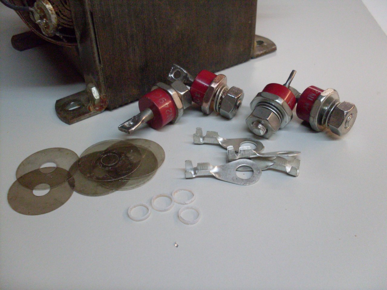
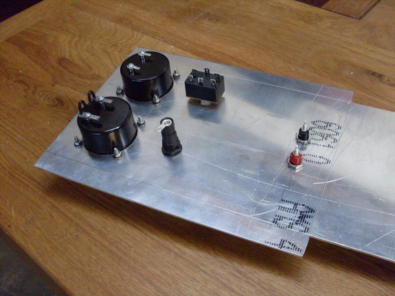
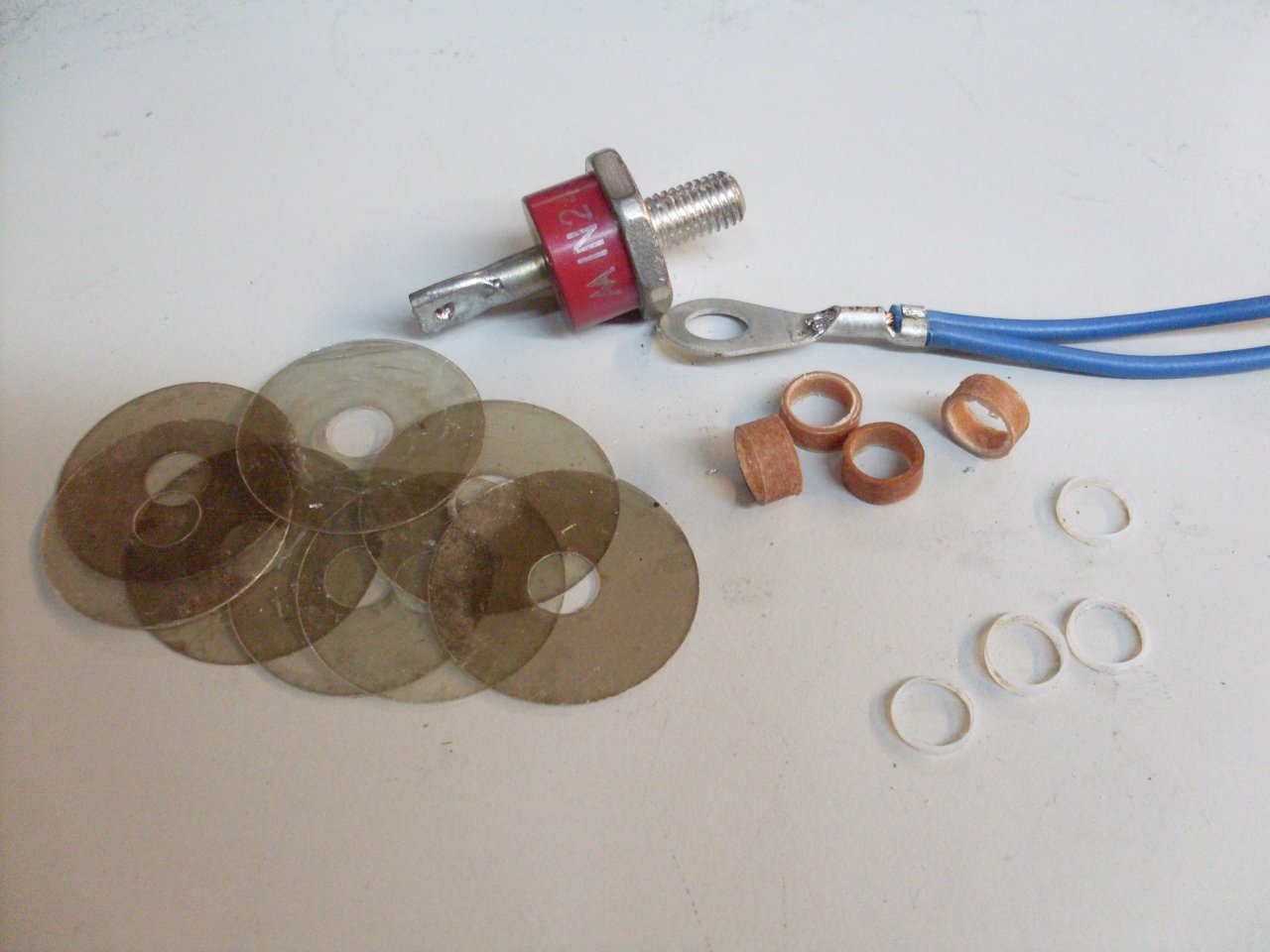
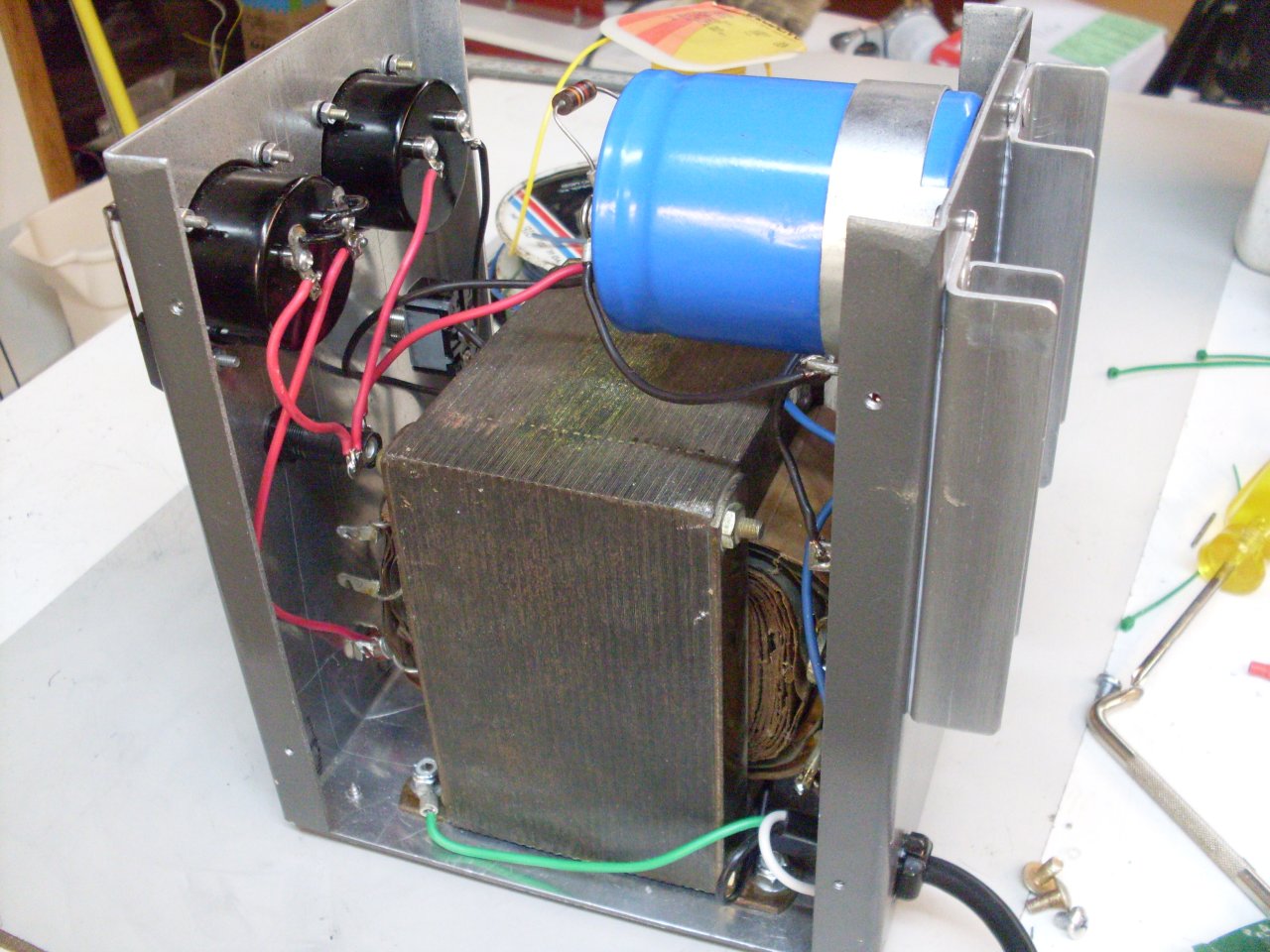
On
the left are 1N249 40 amp diodes from the same found power supply the
transformer came from. I'll re-use the mica insulating washers.
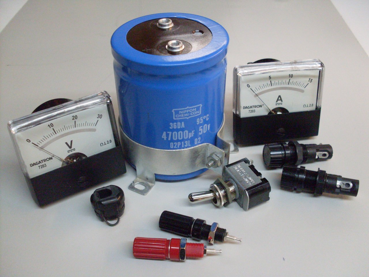
The other picture is the parts I bought new. The old power
supply had some large electrolytics, but I worried about their age.
The new one is more compact, anyway.
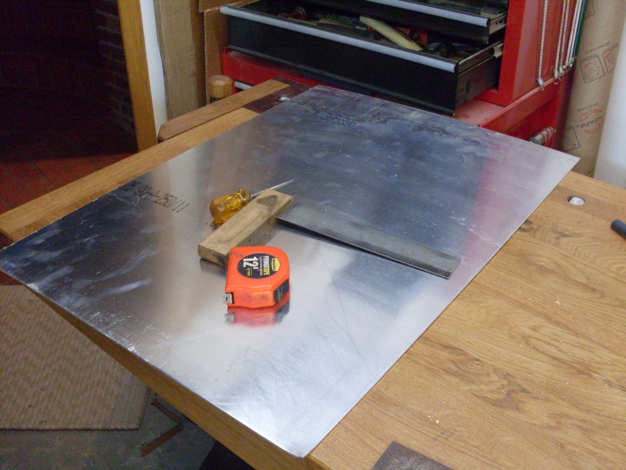
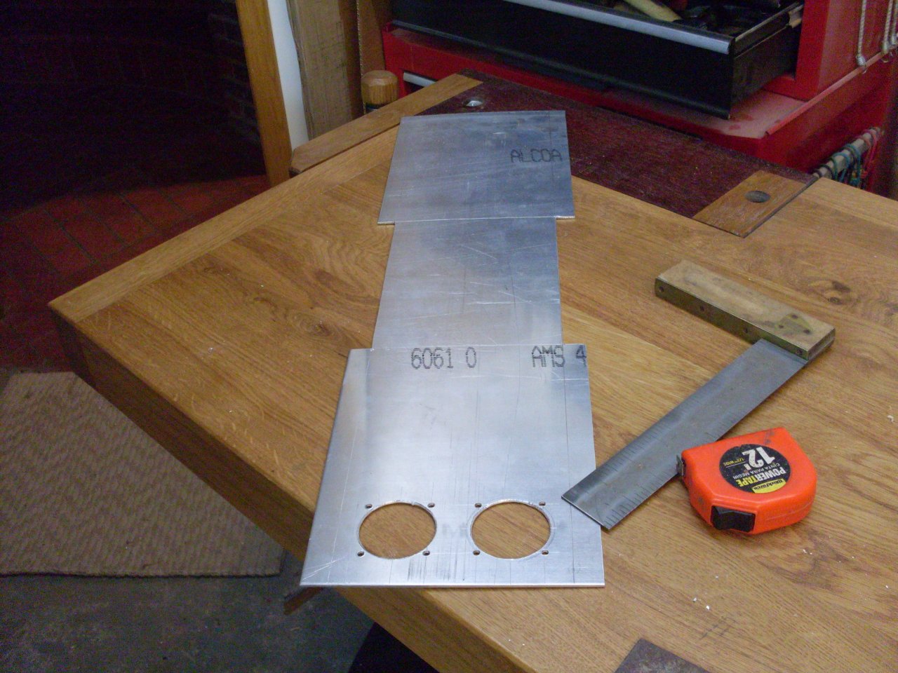
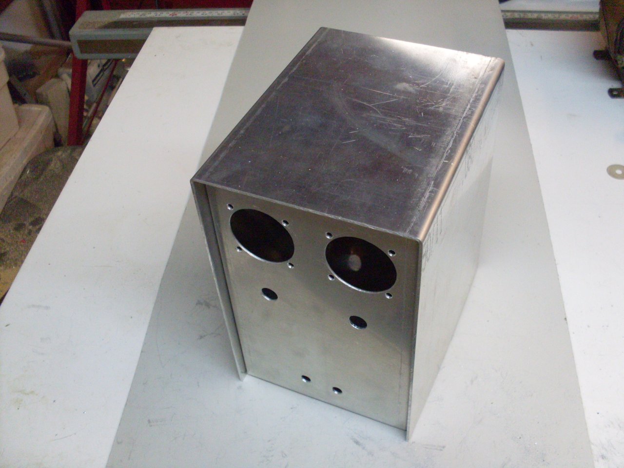
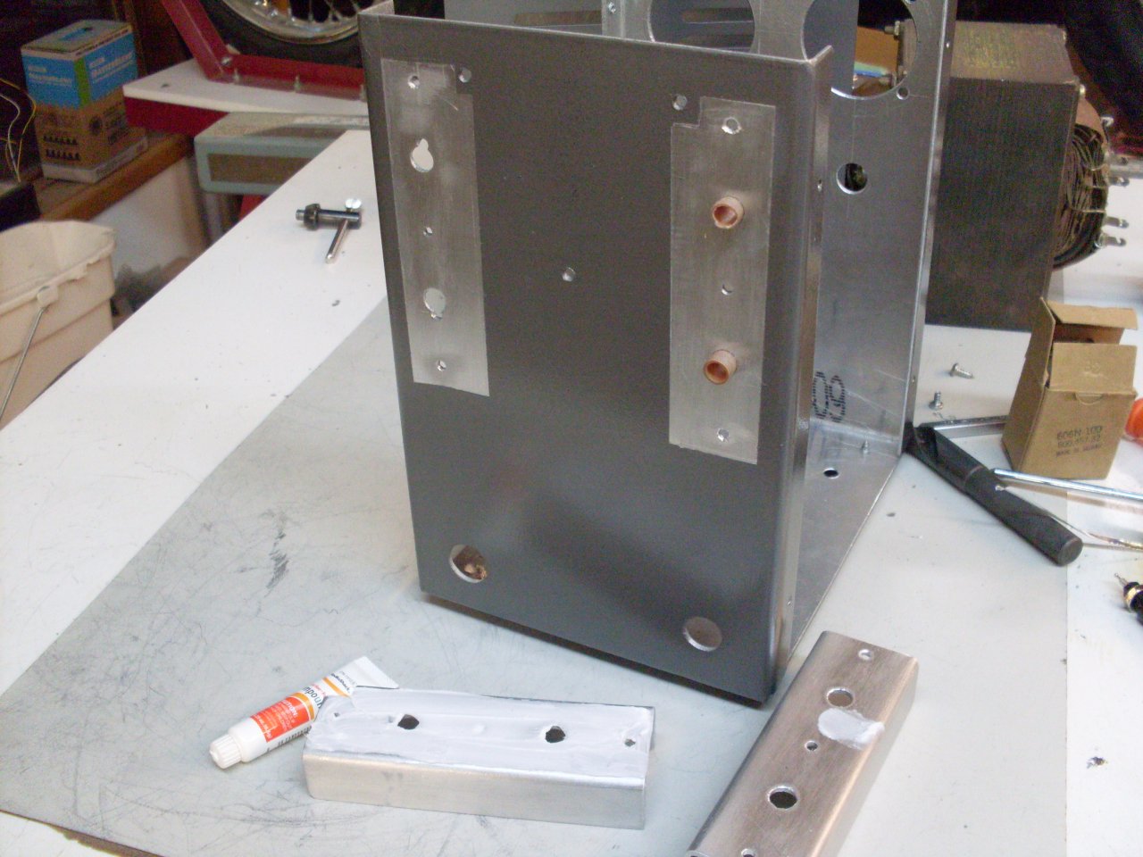
Rather
than use a hobby box to mount everything in, I decided to make a custom
aluminum case that was the same height as the Variac. I got a
piece of 6061-0 sheet aluminum. I believe the -0 means that is
not tempered, and so is soft enough to bend easily. The last
picture proves once again that JB Weld can be a life saver.
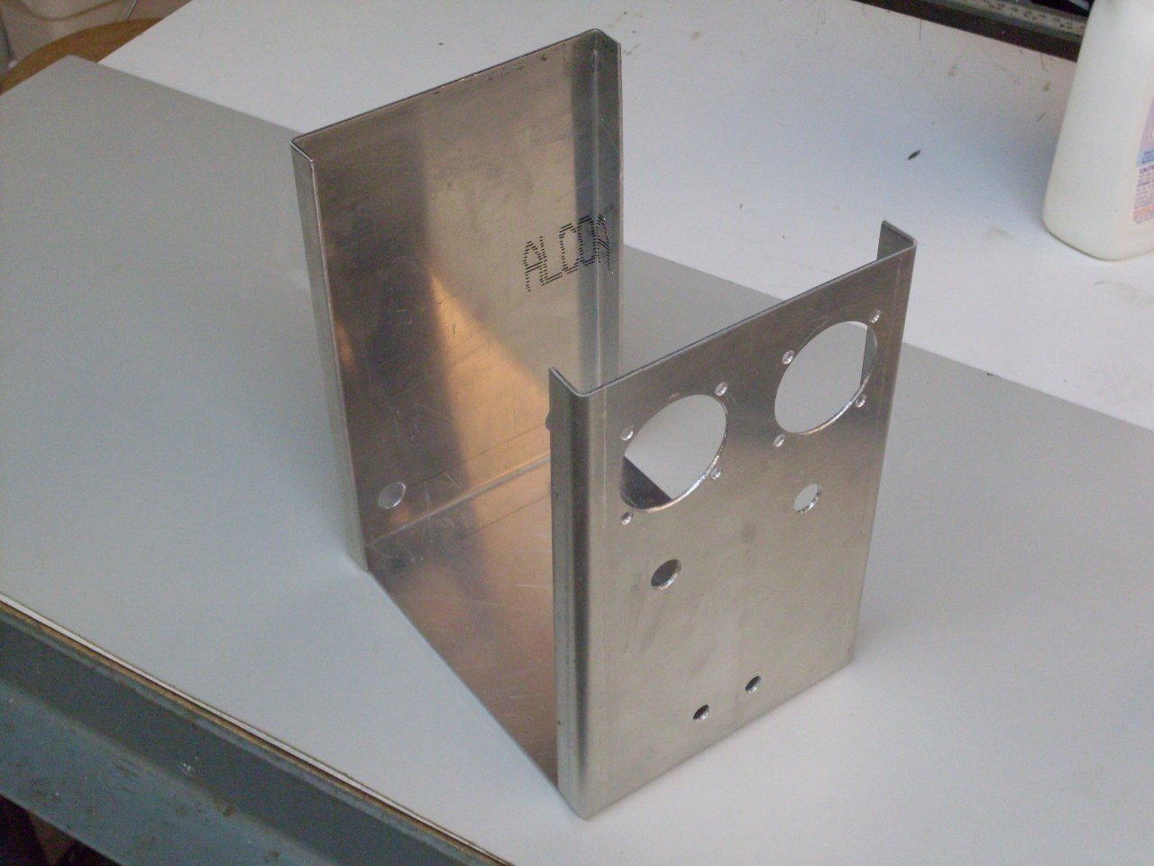
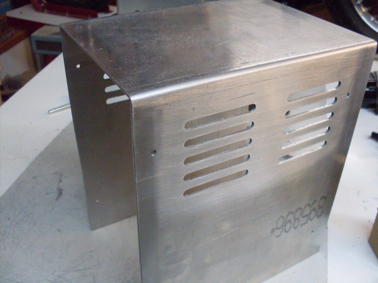
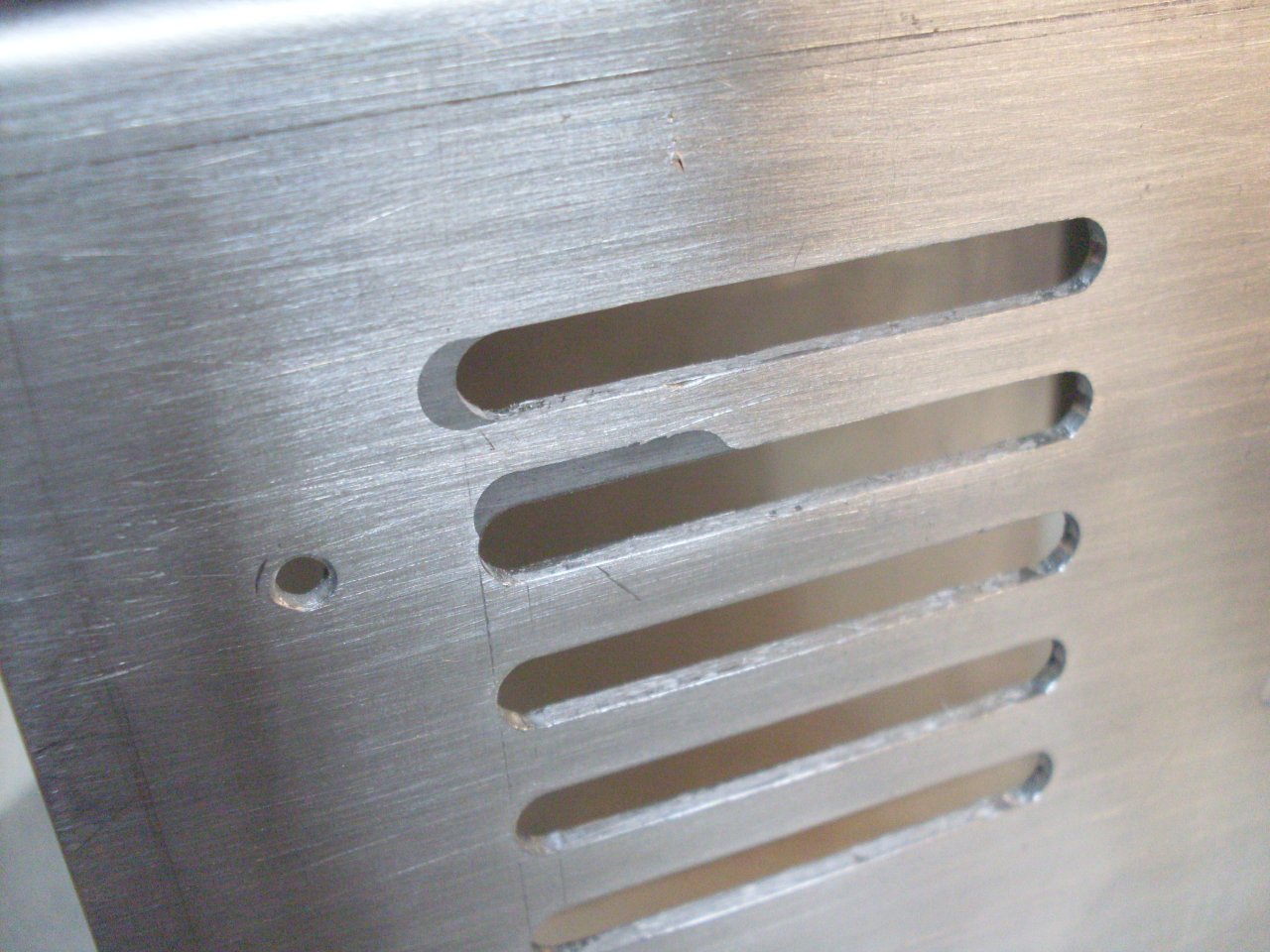
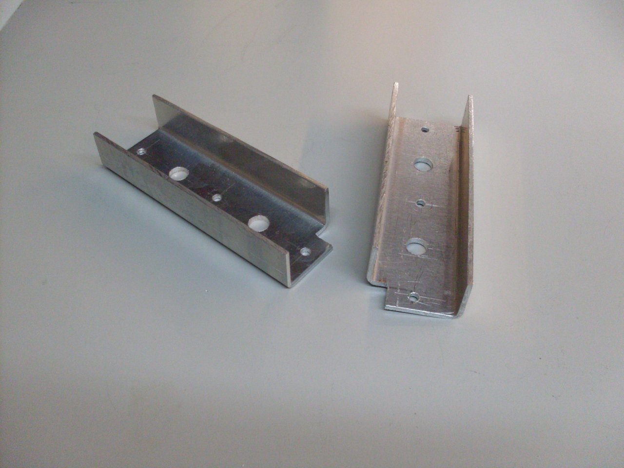
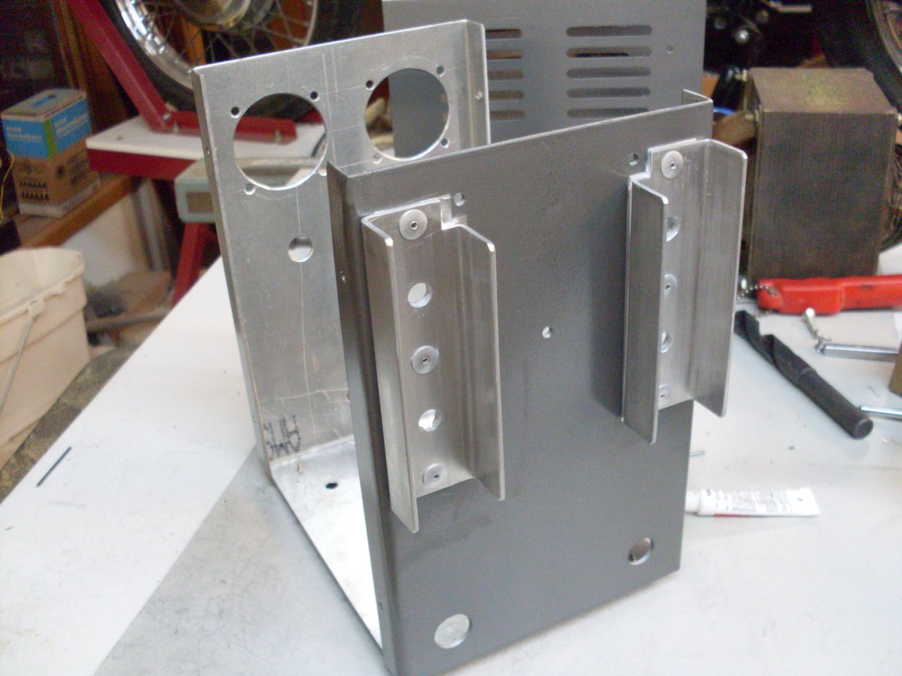
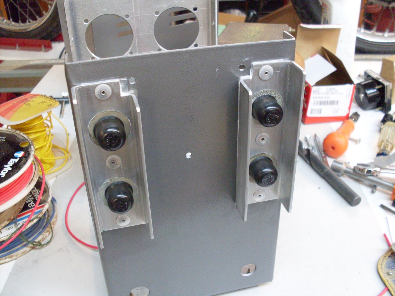
Even
though calculations showed that the enclosure itself provided enough
surface area to keep the diodes cool, I added some heat sink fins just
for insurance. I also made some new insulating spacers for the
diode studs in the thicker panel. I painted the box with a gray
hammertone to match the Variac, but masked where the heatsinks would
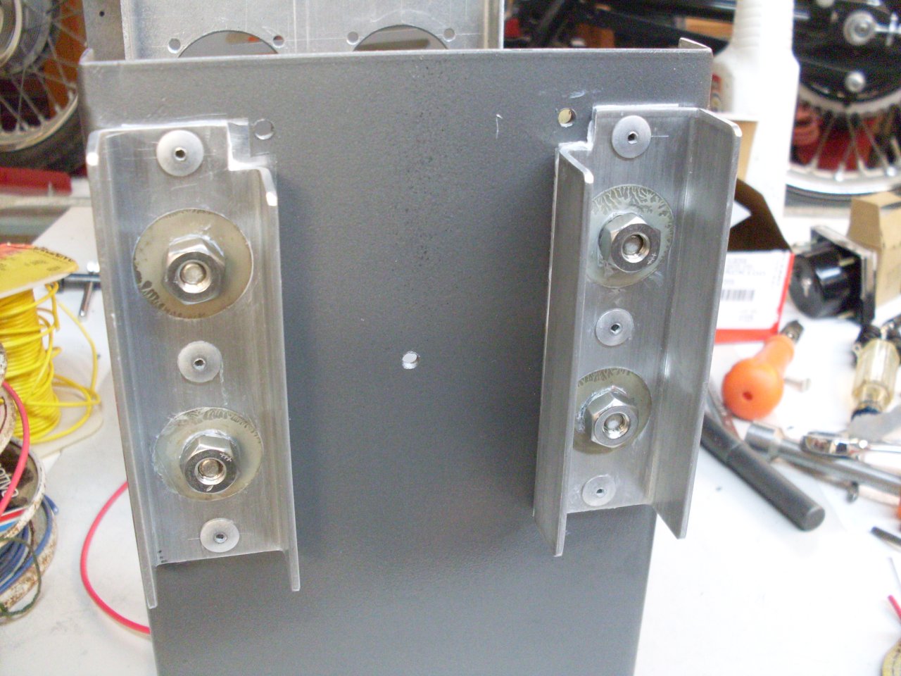
mount. The heatsinks are attached with aluminum rivets, using
liberal heat sink compound to improve heat transfer. Last picture
shows plastic caps on the stud nuts. They are electrically hot,
so I don't want them shorting to anything.
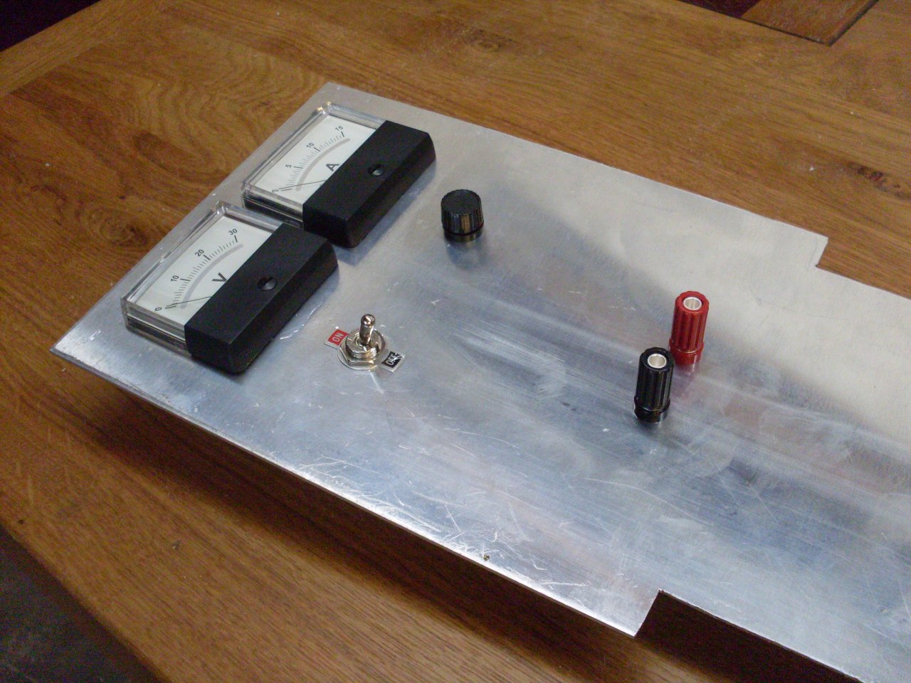
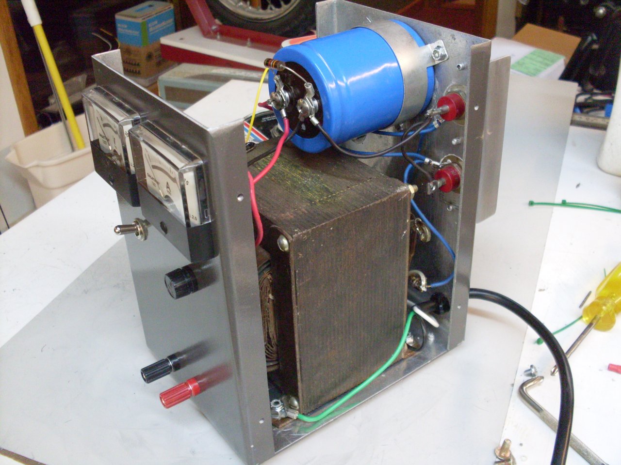
Wiring
is straightforward. Its a standard bridge rectifier with a
capacitive filter. The AC is fused at 4 amps, the DC at 15.
Ammeter with builtin shunt is wired in series, voltmeter across
the output. Power switch is in the primary circuit. There
is a bleed resistor across the capacitor to drain charge when the
supply is turned off.
Final setup seems to work OK. Can't wait to try it.