Just about all British sports cars of this era had the obligatory manual
gearbox with four forward speeds and a reverse. Being of a
certain age though, this car and its close cousins all had no use for
the sissified synchromesh for all four gears. First gear was
strictly for selection while stationary, or, for real drivers, double
clutching.
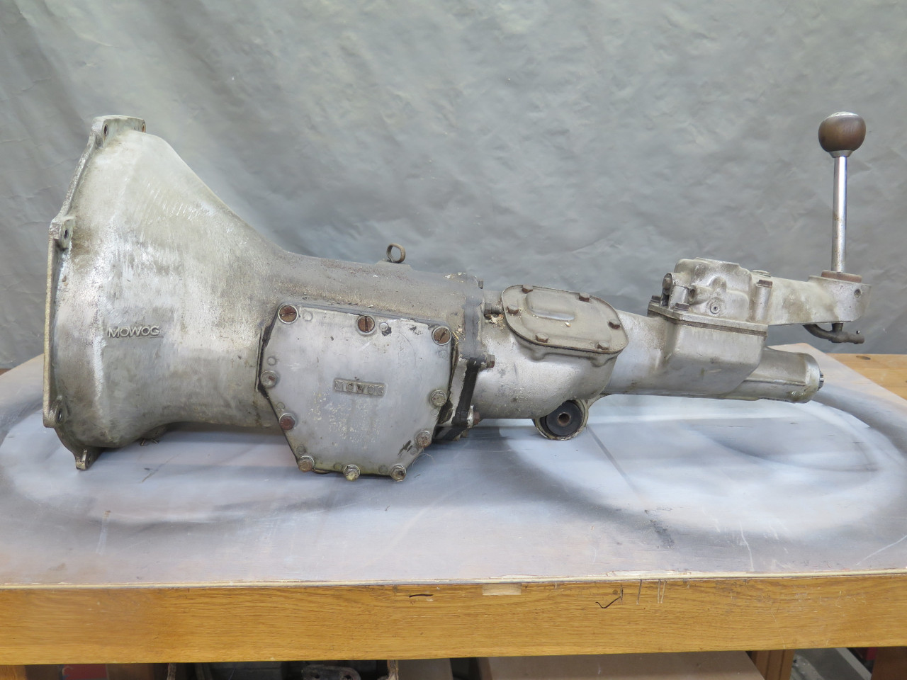
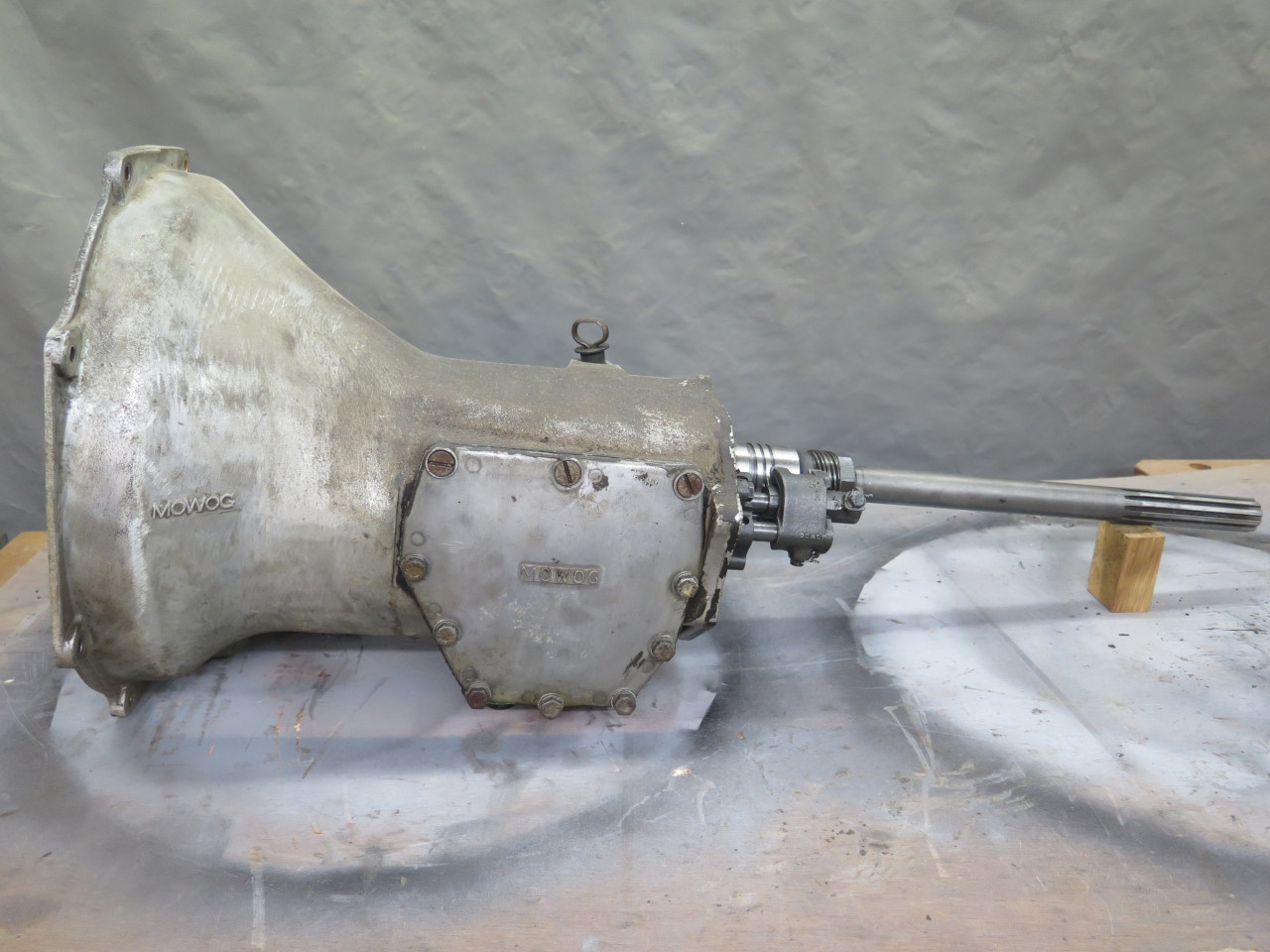
The MGA used a few variants of the same gearbox over its tenure.
This box is the original one that came with my 1957 1500 roadster model.
Since this will be a rather long page, I'll offer some skip-ahead links for the various sections:
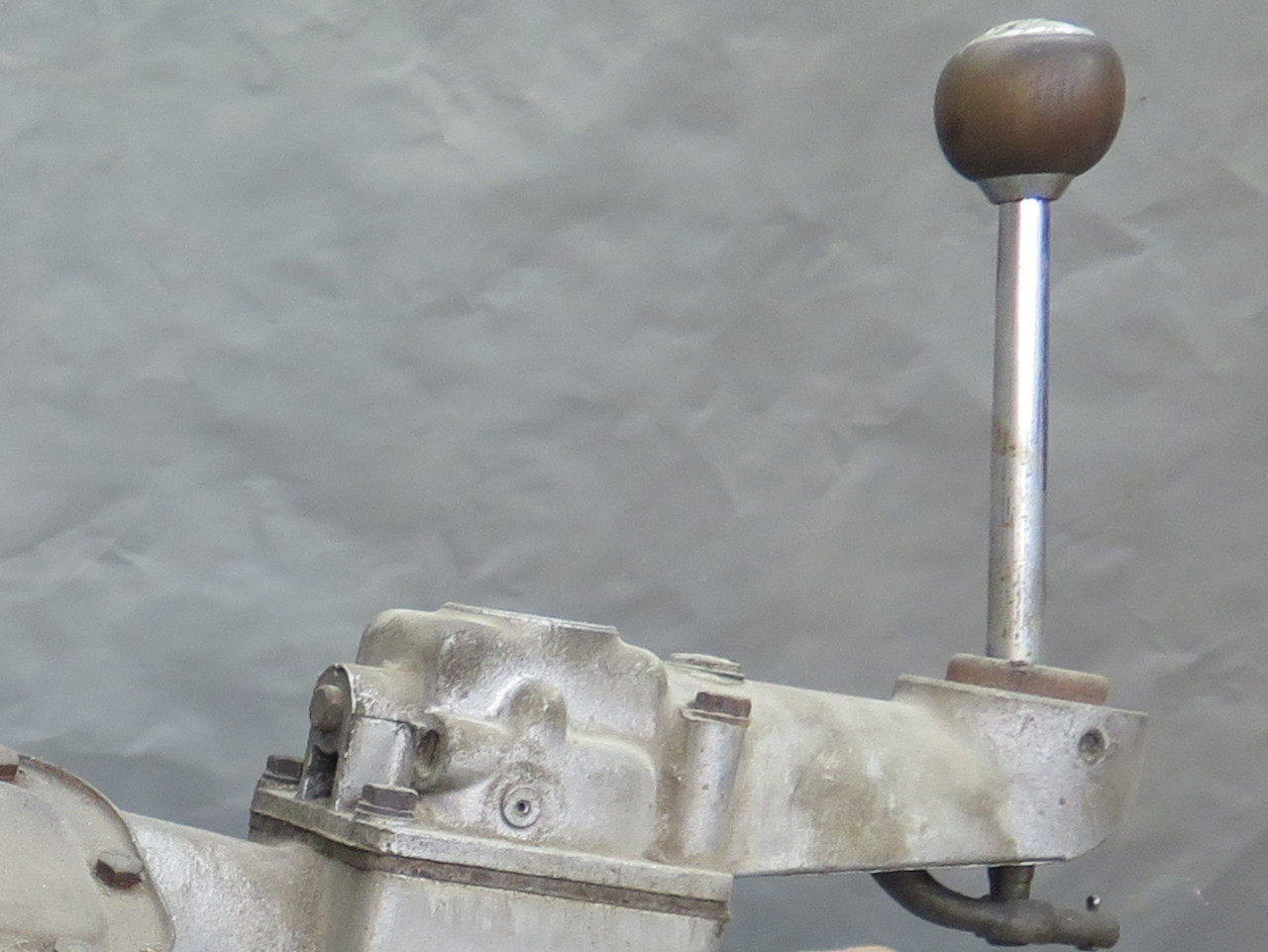
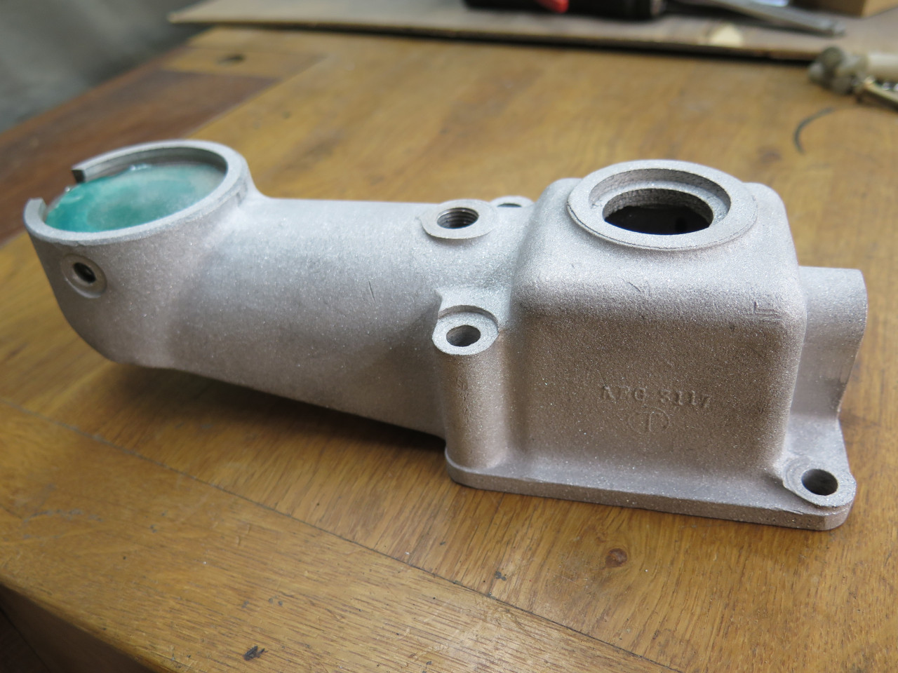
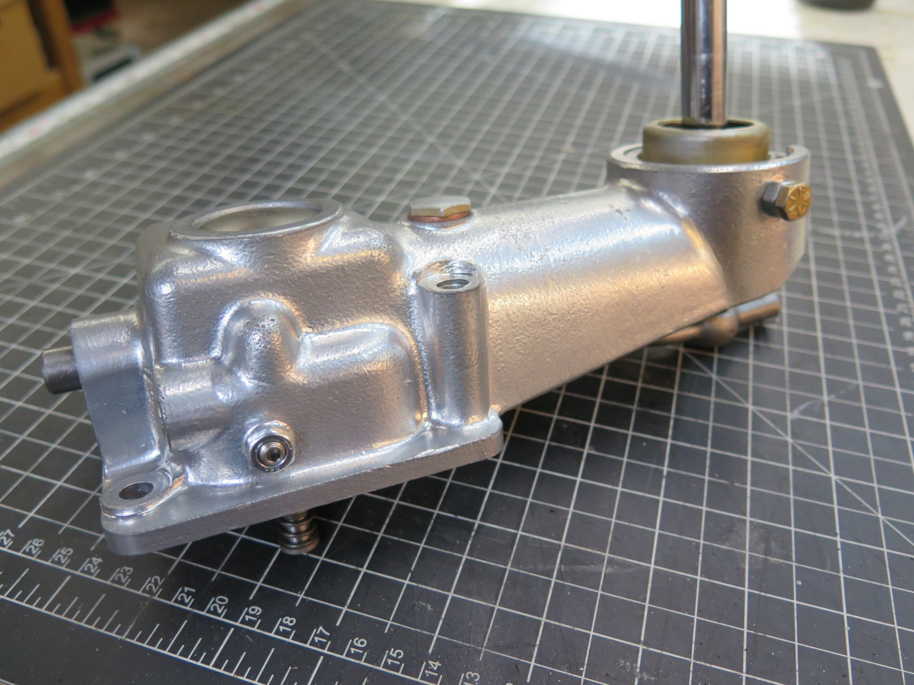
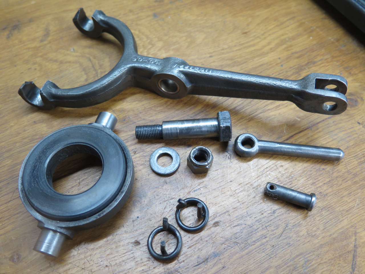
The remote control tower's main job is to position the shift lever within easy reach of the driver.
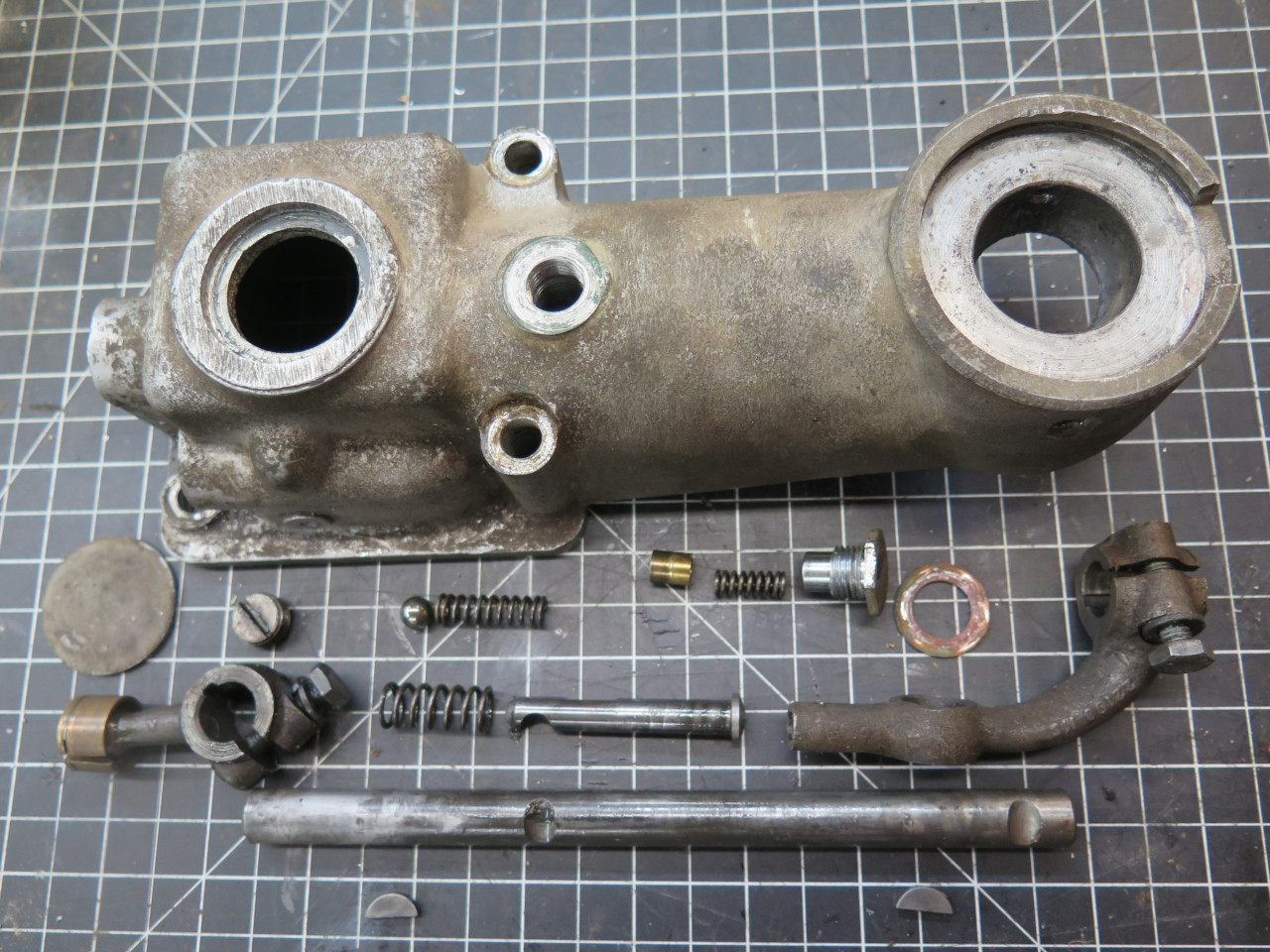
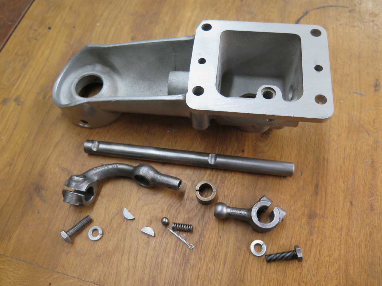
There are a fair number of parts in the tower.
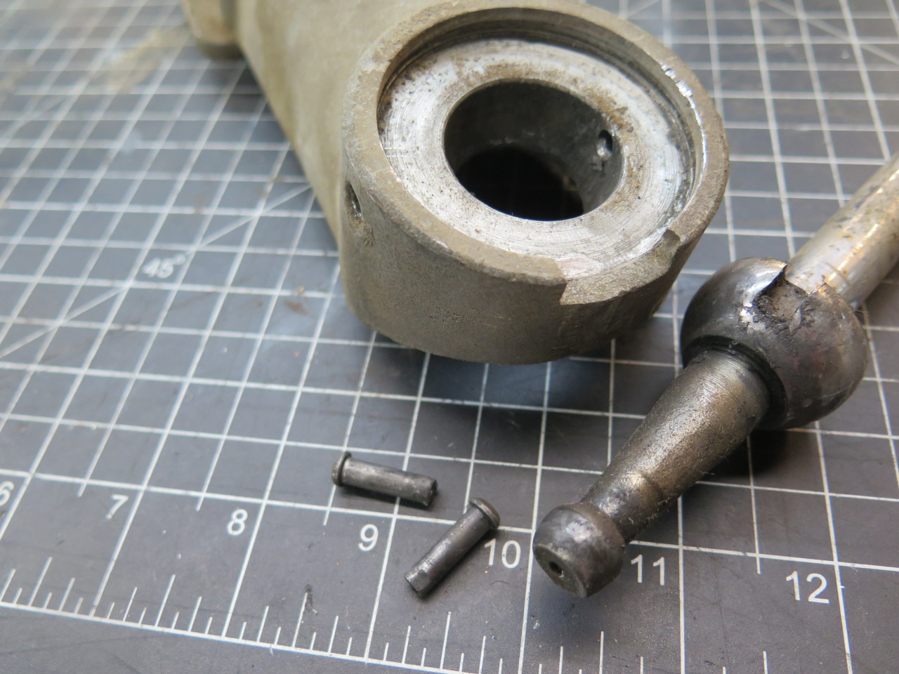
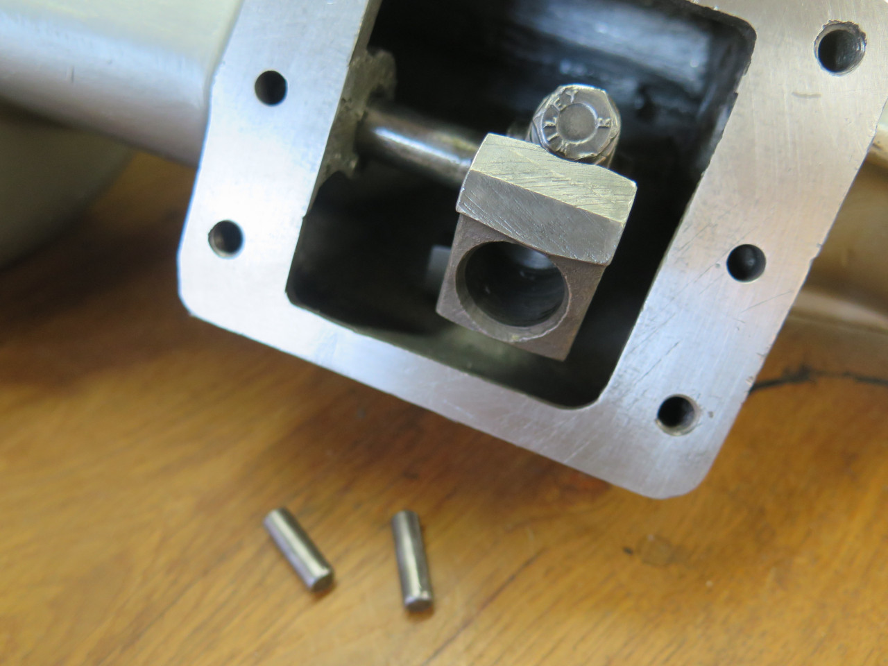
The shift lever swivels in a ball and socket joint, and is captured by a
pair of little pressed-in pins. This makes it sort of a pain to
extract the lever. It's not hard to imagine an better way to
assemble this joint, and I'm sure I'm not the first to think this.
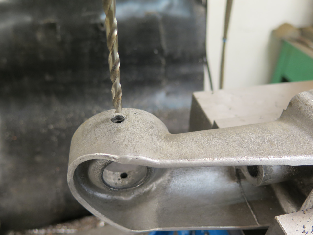
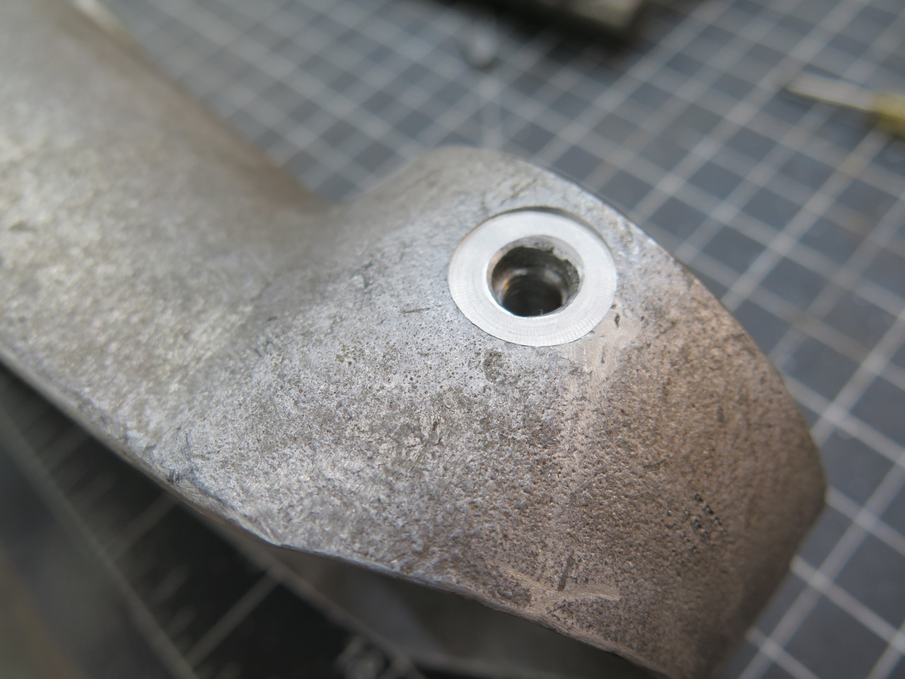
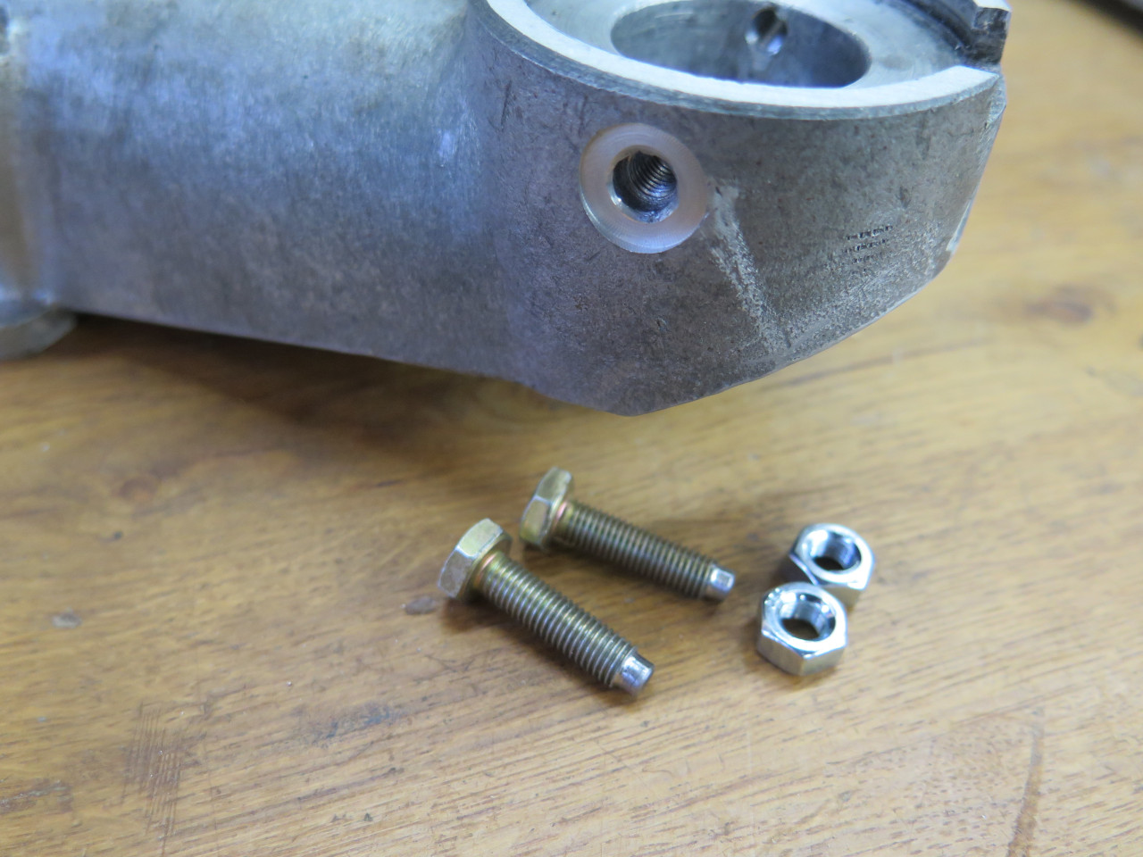
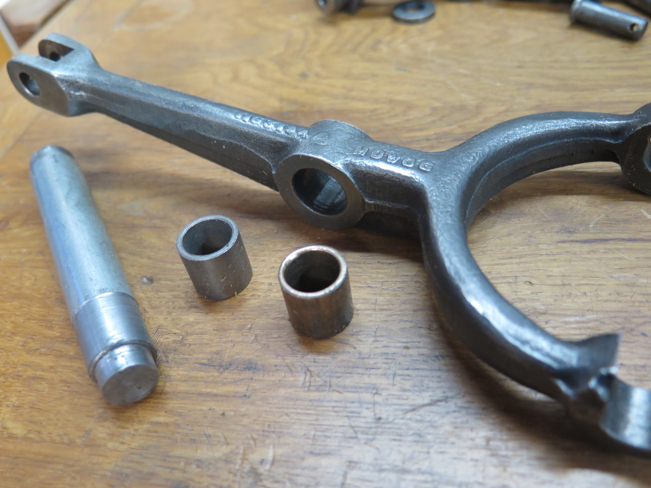
Easily removable threaded fasteners seemed like a good plan. I
drilled and tapped the existing holes for 1/4-28 screws, then machined a
little flat land for seating a lock nut. Then made a couple of
bullet-nose screws to mimmick the ends of the pins.
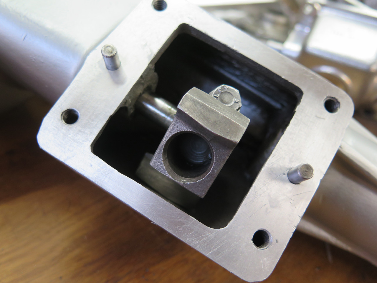
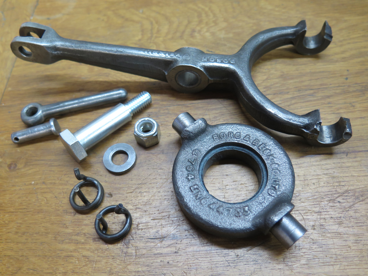
Before going too much further, I gave the casting a light media blast.
After a nice silver powder coat, I finished the cleanup by linishing the
mounting surface flat. Then installed the shaft with its
specialized arms keyed to each end.
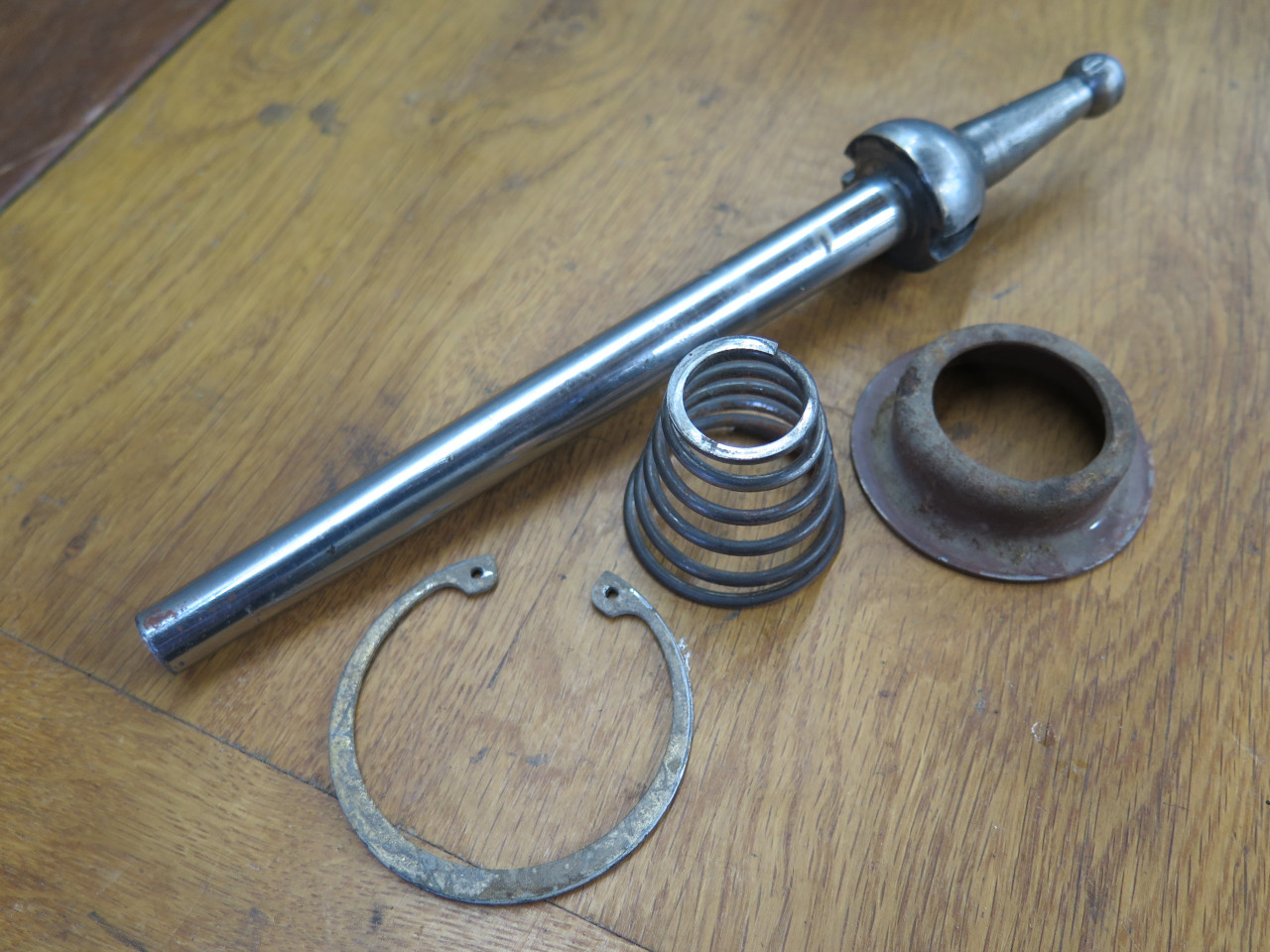
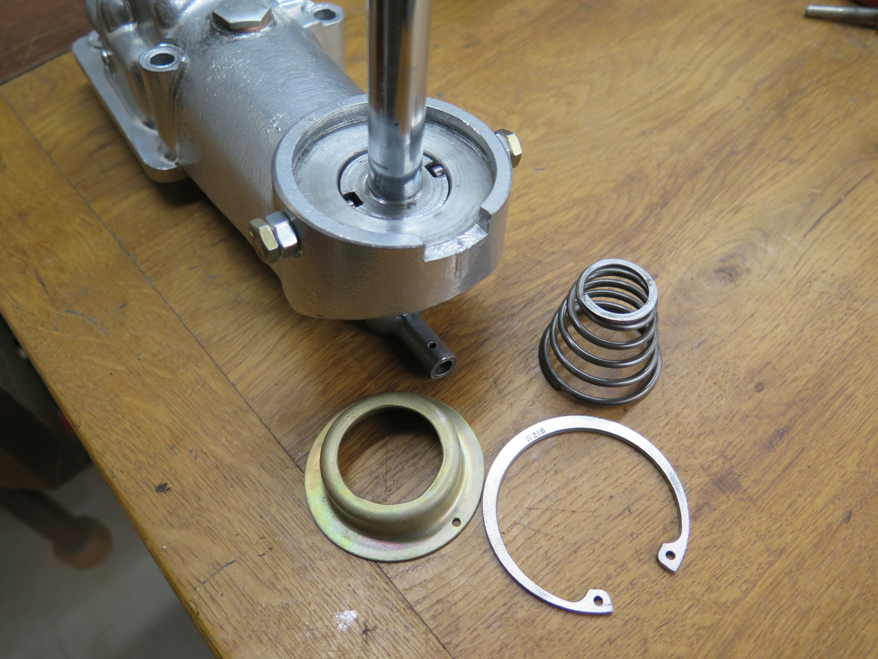
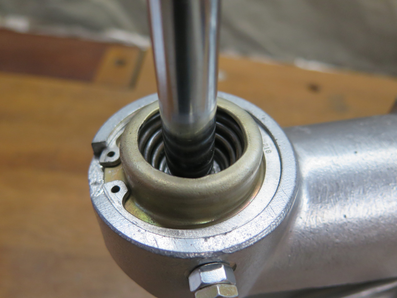
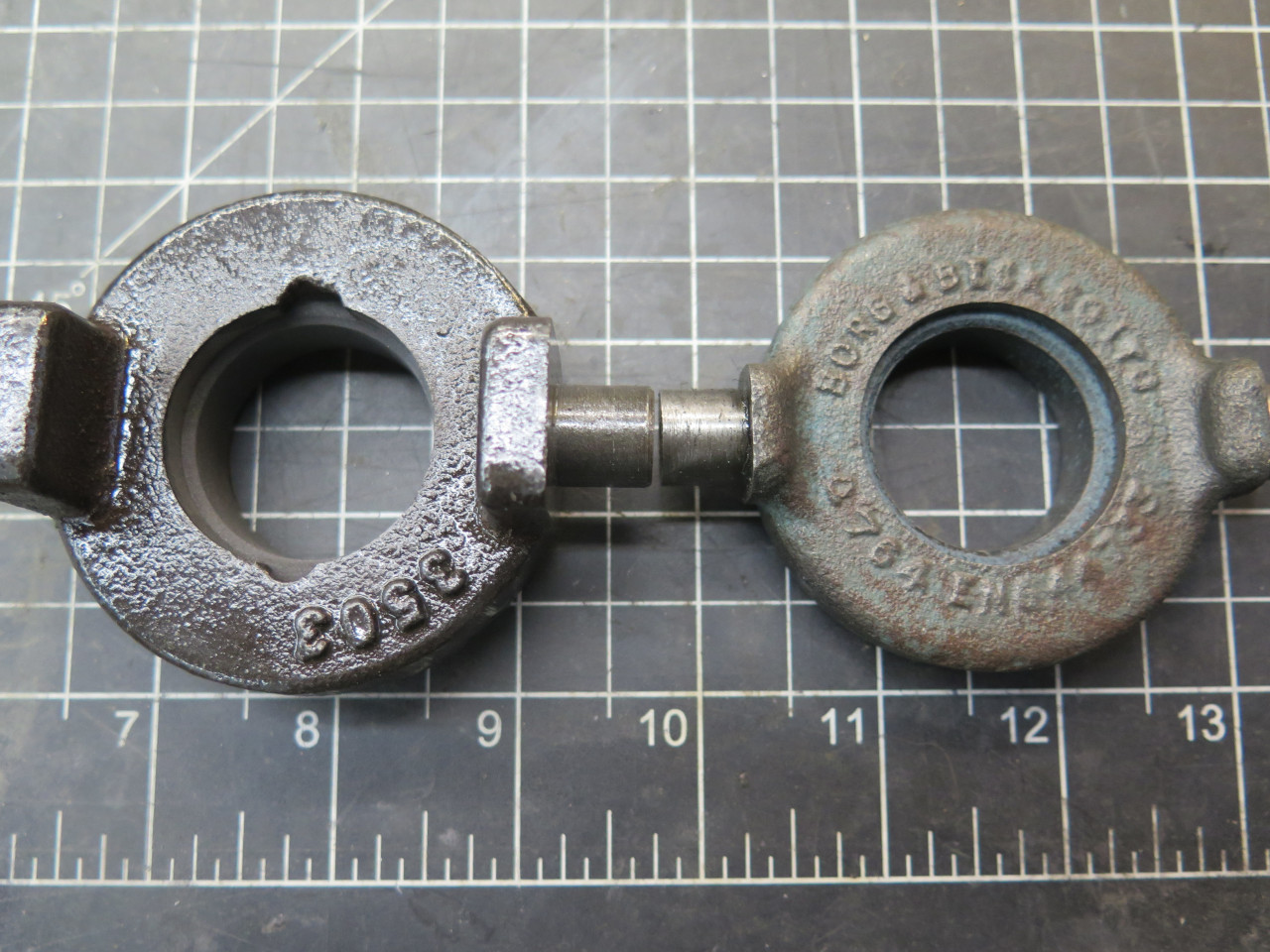
The lever is held in the socket by a spring and a cap retained by a
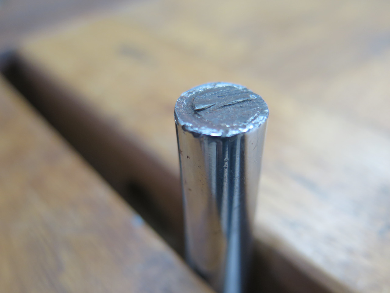
large C-clip. My shift lever had seen some violence in its
life. I assume it was born with a threaded stud on its top end to
receive a shift knob, but it had clearly been sawn off. I think it
might even have been me that did that. I vaguely remember having a
knob that had its threaded insert come loose inside the knob, so the
knob would twist freely, but not come off.
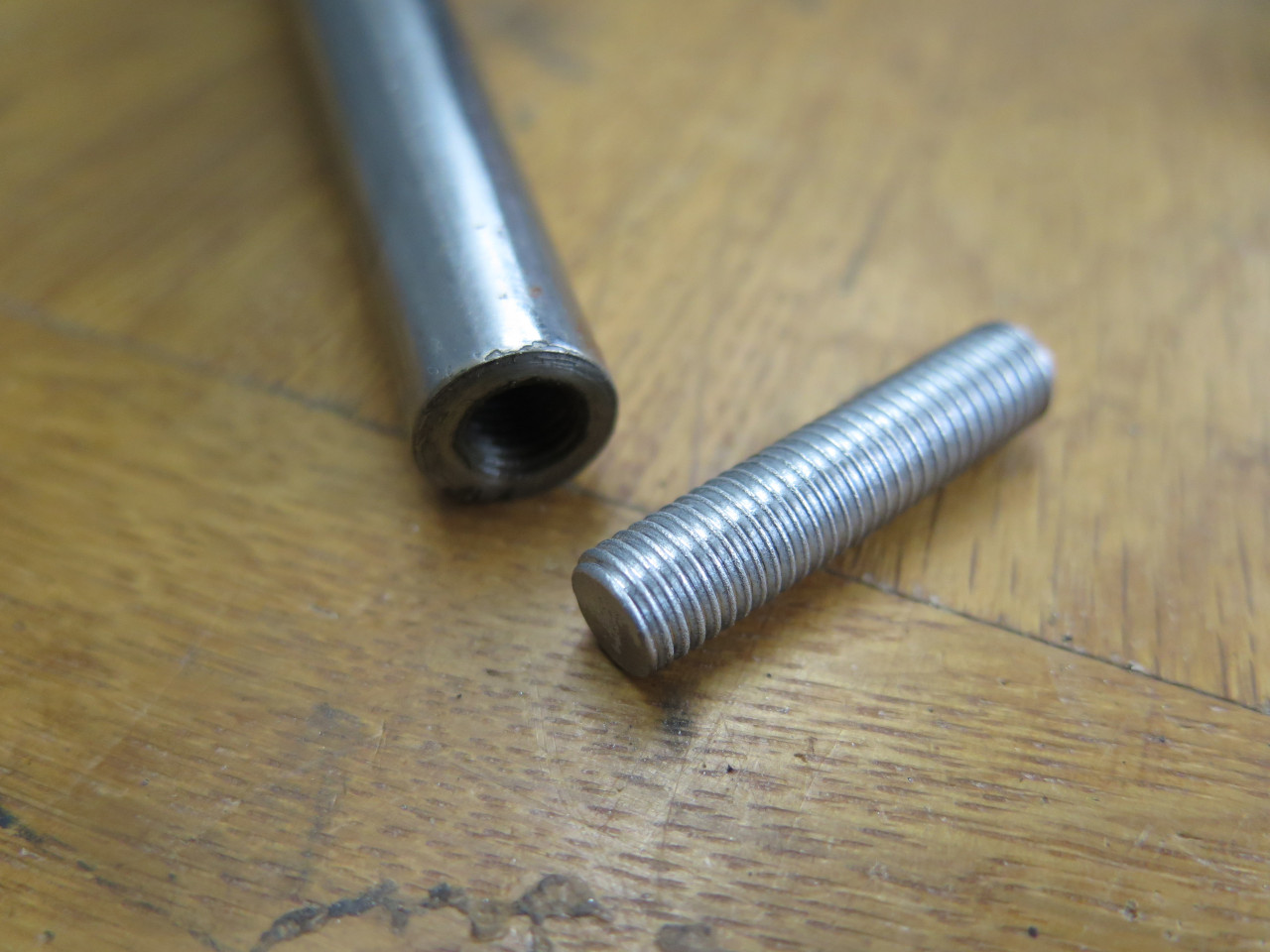
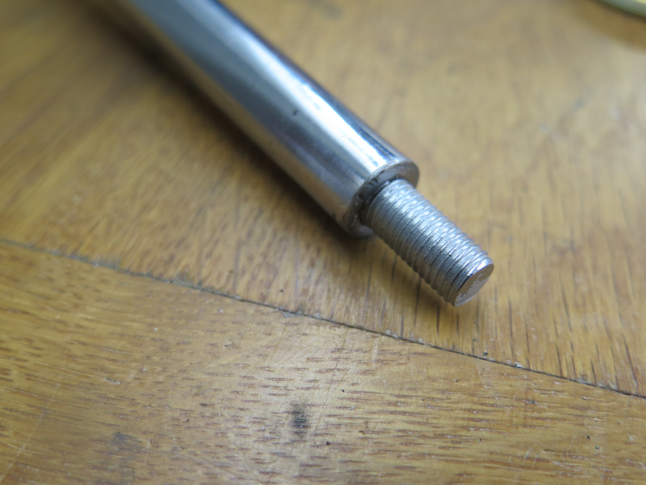
To rescue the lever, I just drilled for a threaded stud, and Loctited it in.
Then cleaned up the retaining parts and replated the cap, which was pretty rusty.
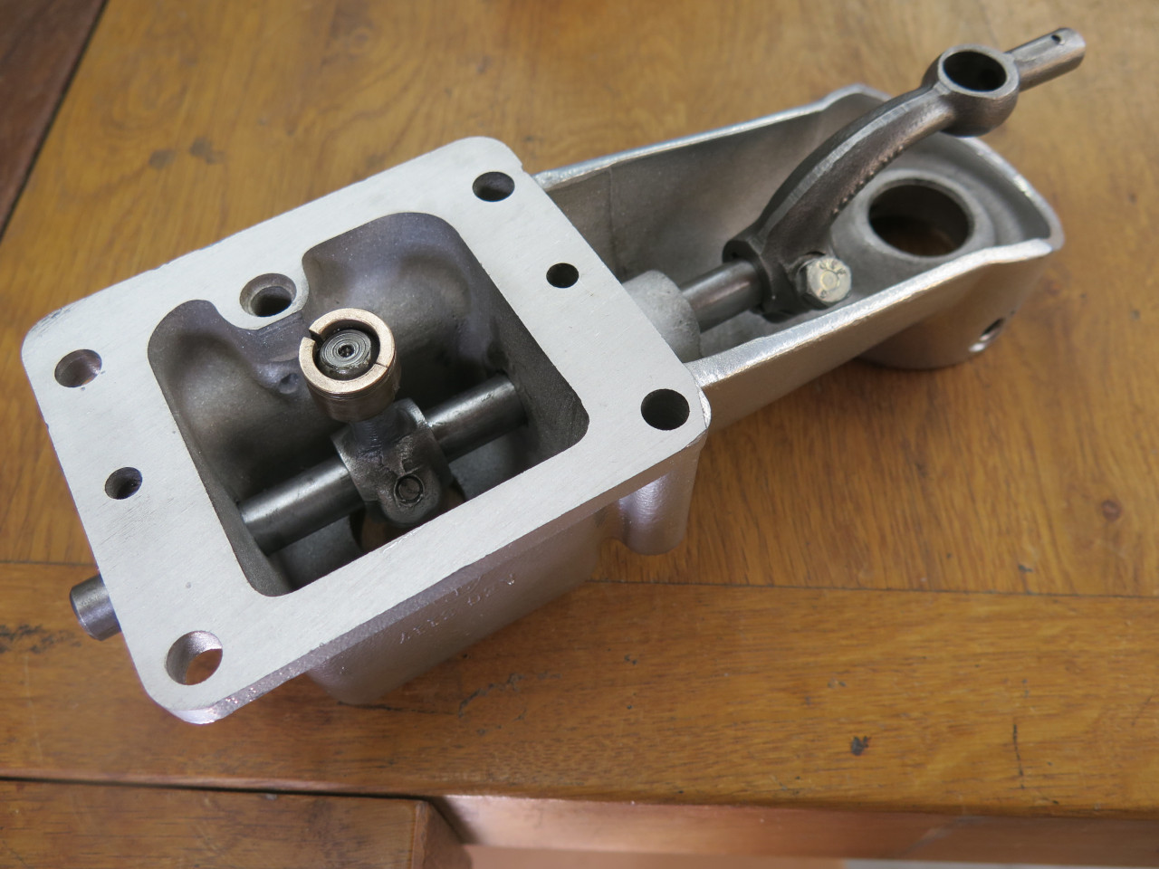
The bottom end of the lever fits loosely into an arm on the shaft, and
there is a little spring loaded ball to keep the rattles to a minimum.
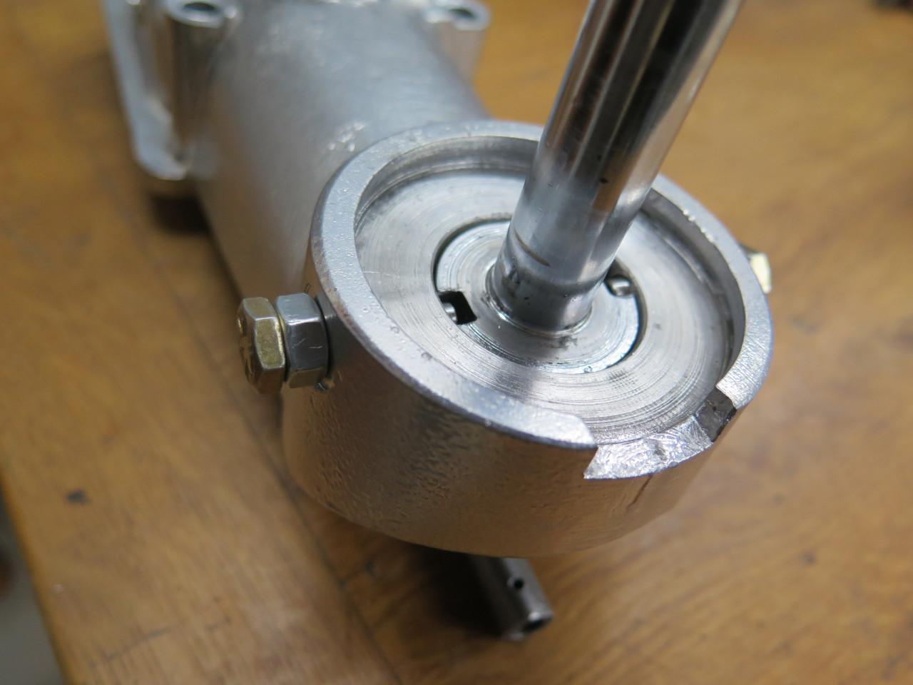
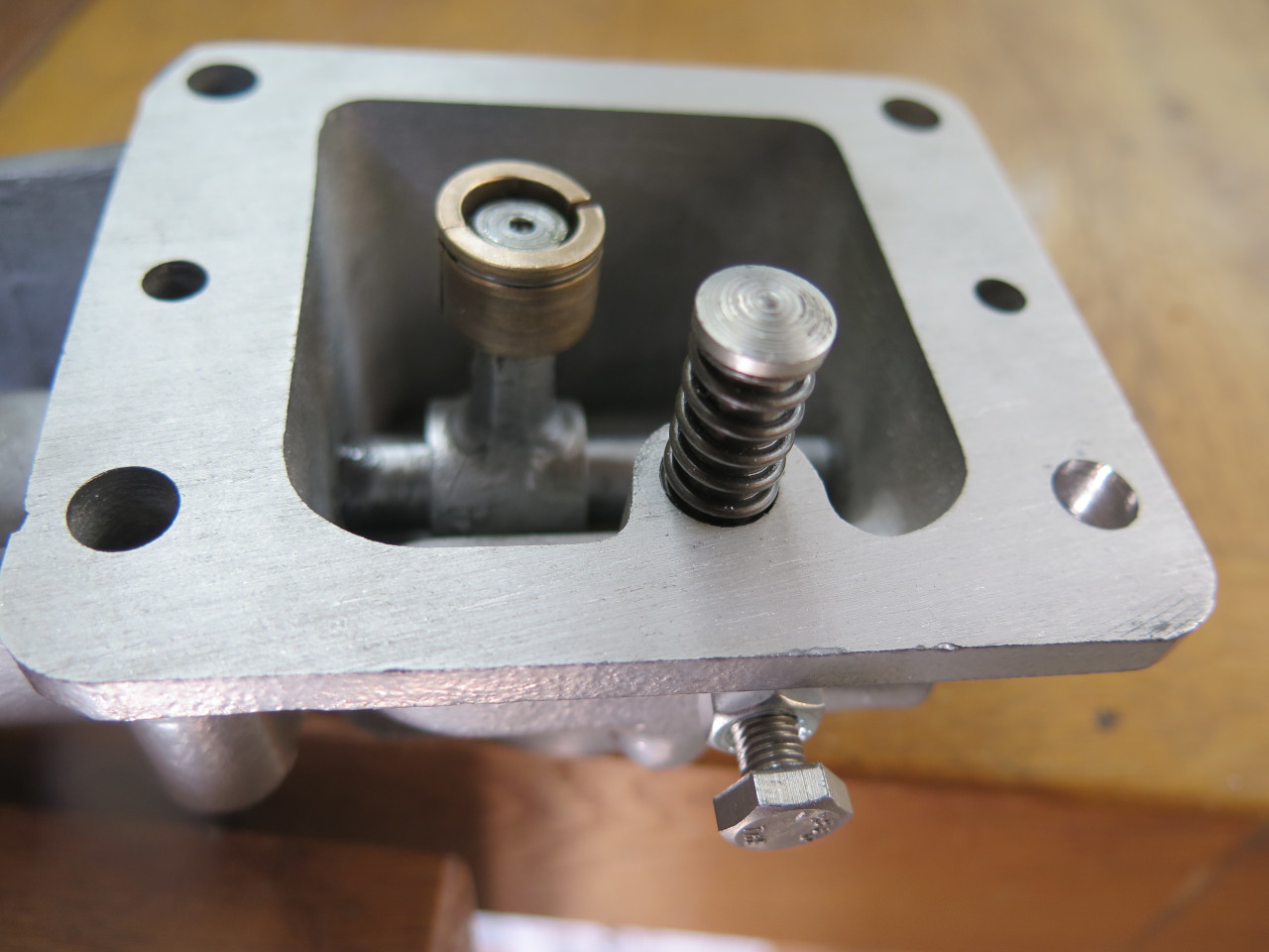
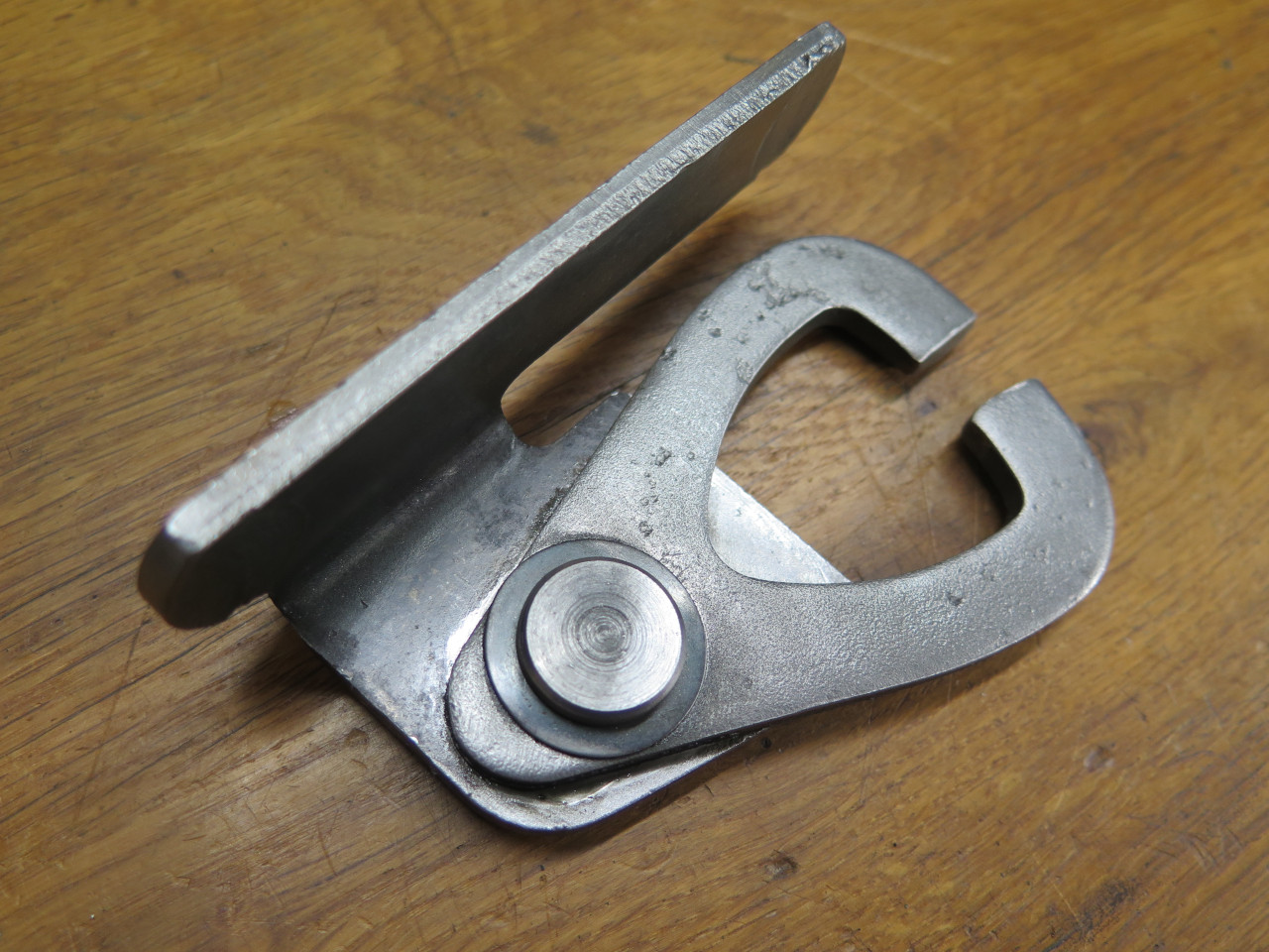
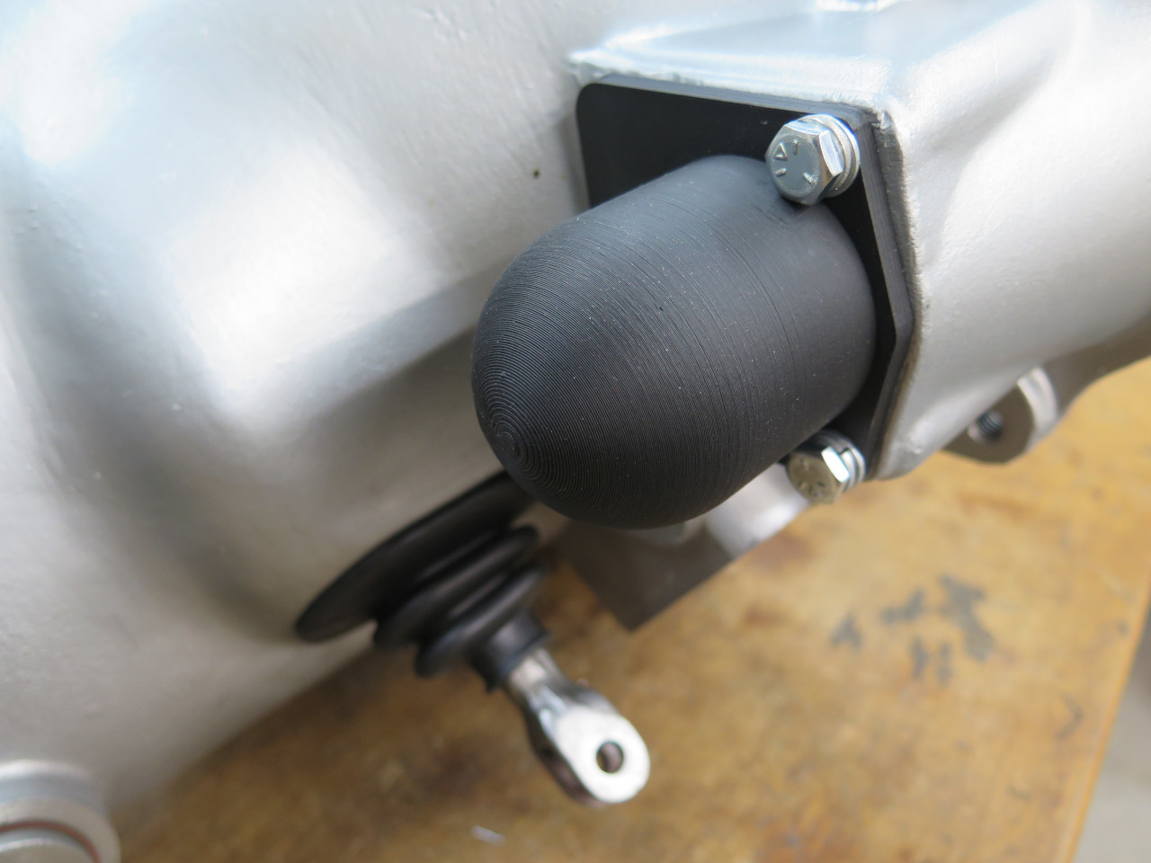
One other piece of trickery on this part is a spring loaded plunger
arrangement off to one side of the mounting opening. This plunger
gets depressed by the arm when the driver moves the lever to the far
left to select reverse gear. It offers some extra resistance to
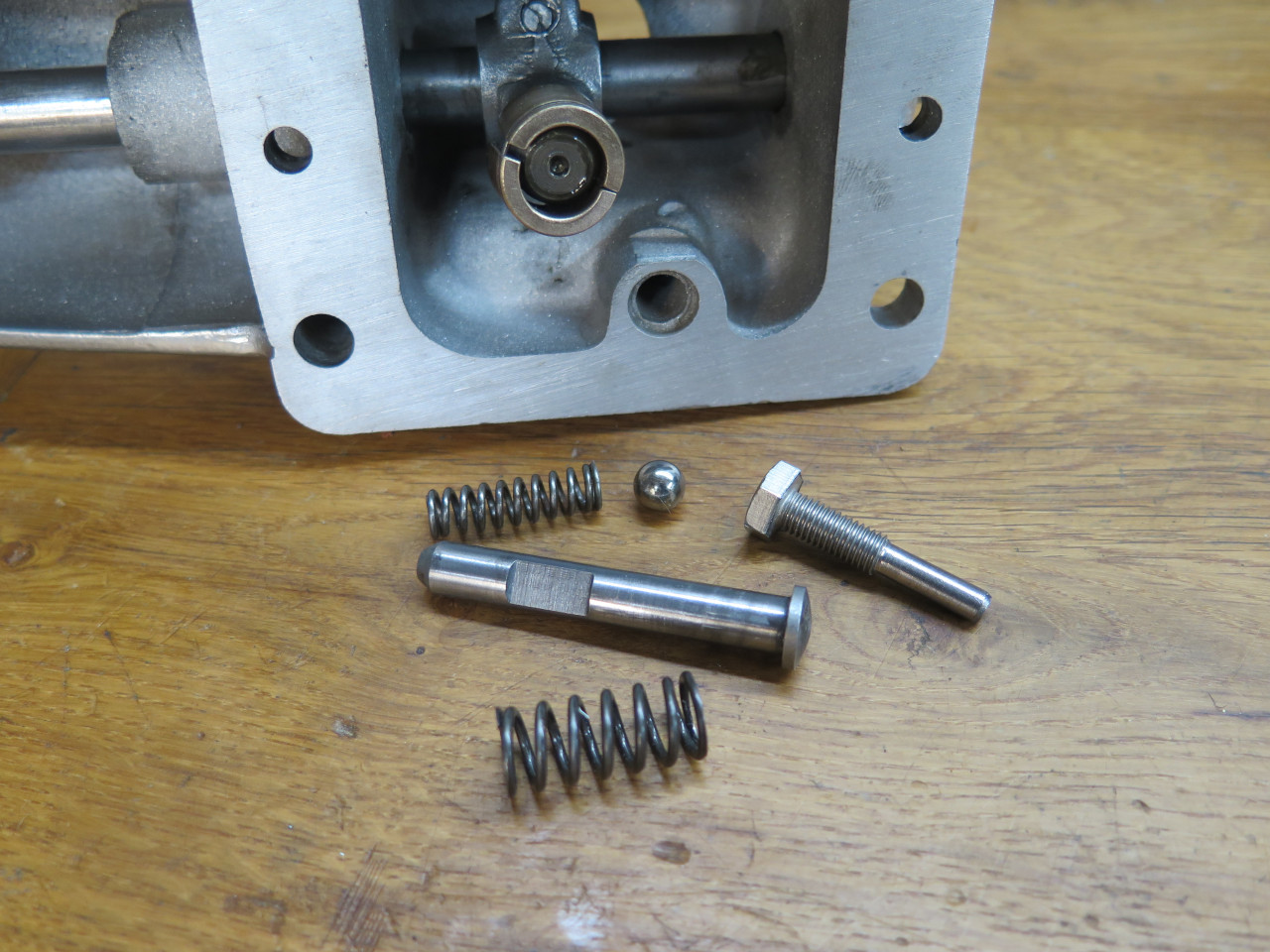
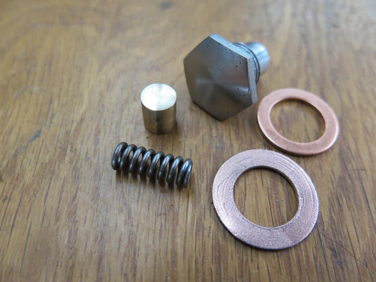
help avoid unintentional backing up (or worse). The larger spring
keeps the plunger in its rest position, while the small spring and ball
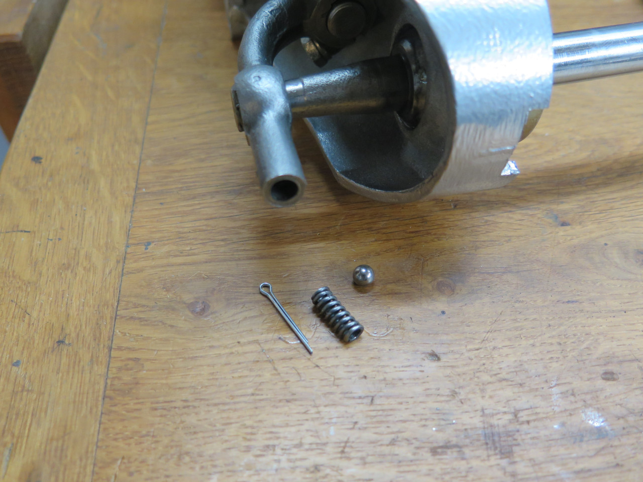
give a detent action to the plunger. The plunger was originally
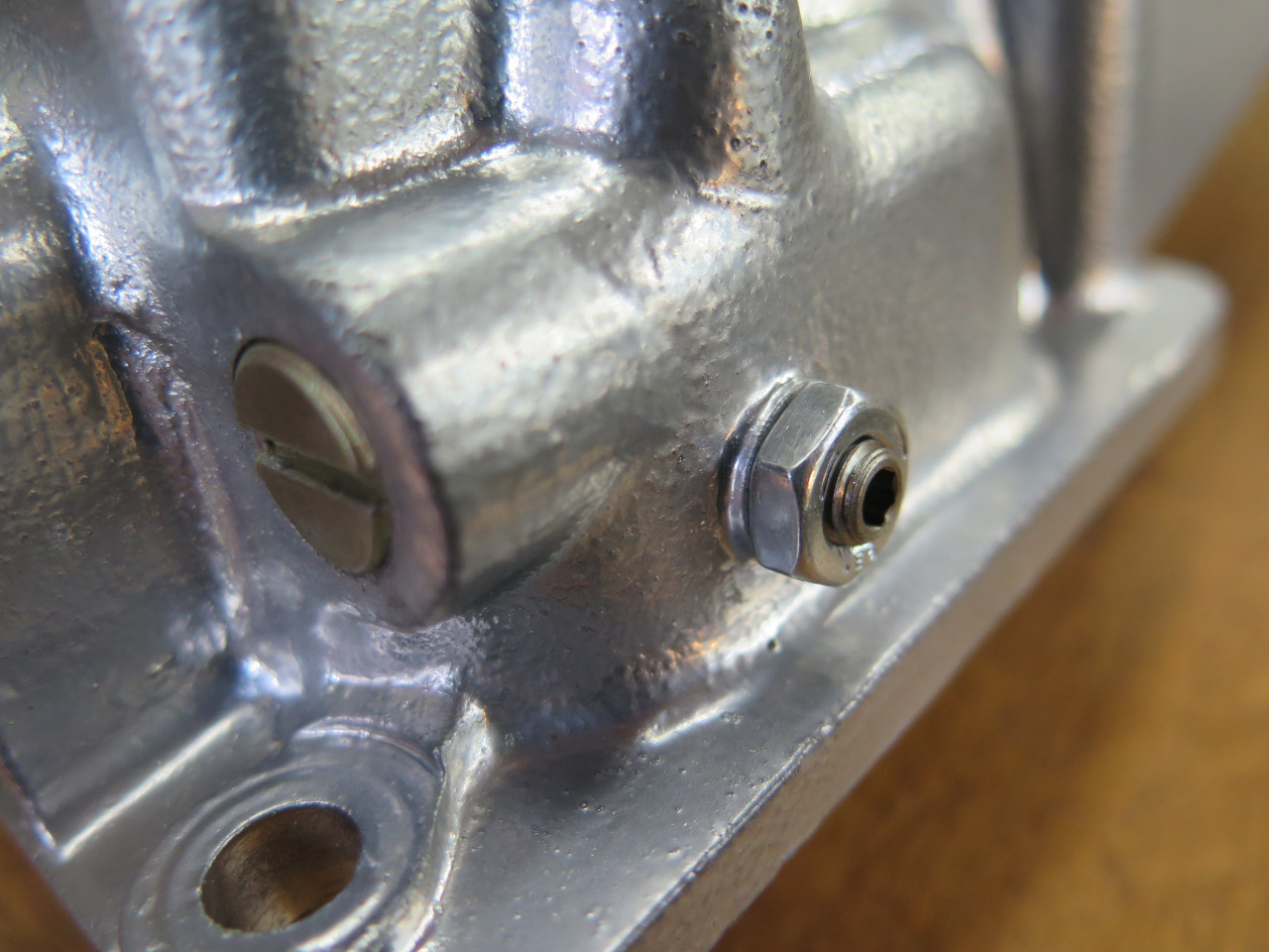
captured by a simple roll pin passing through that depression. I
replaced that pin with the threaded one shown, similar to the shifter
retaining pins. I later replaced it with a locked set screw
because it looked less clunky.
I'll have to say that assembling that plunger with its infernal detent
was a really unpleasant experience. More on that later.
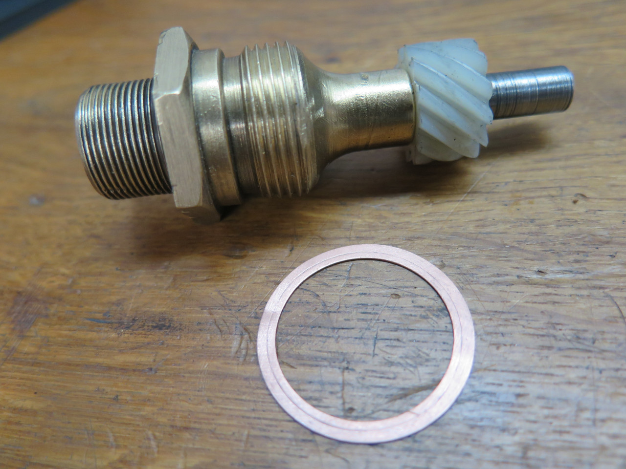
There is also a damper gadget on the top of the tower. It is just a
spring loaded wiper that bears on the shaft that adds some drag to its
movement, making it feel less loosey goosey. The big copper washer
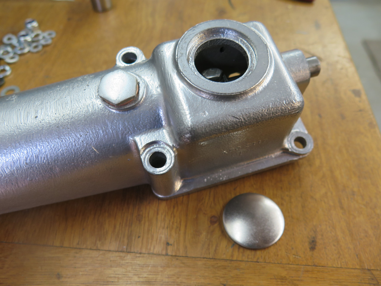
was original, but the smaller one fits way better. The last
item to install was a core plug to cover the gaping hole in the top of
the casting. That hole was necessary to access the fastener for
the shaft arm beneath it.
The finished tower. The chromey powder coat was a bit of a
mistake. I intended something a little less blingy, but I had a
mismarked jar of powder. I probably won't fix it. I like to
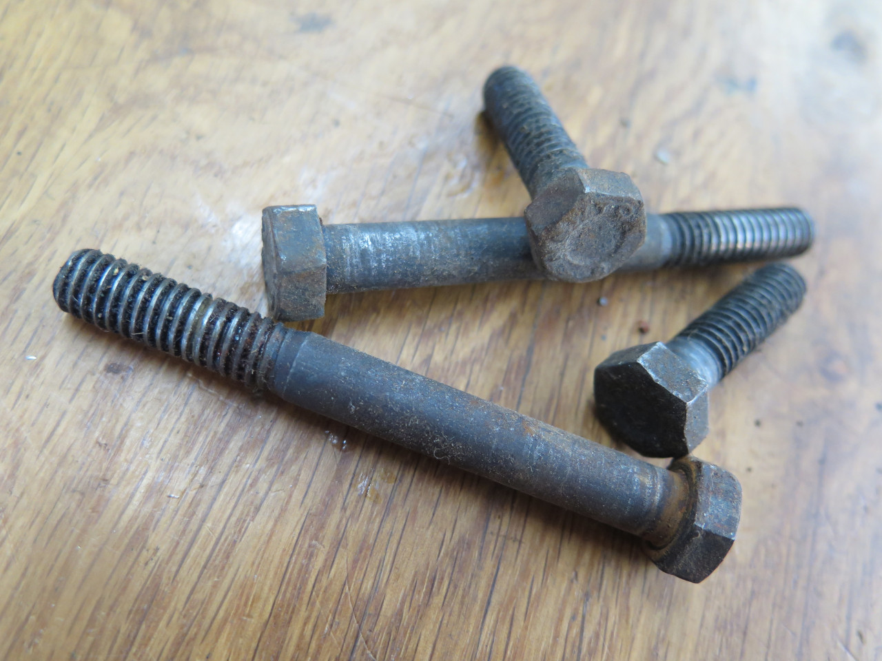
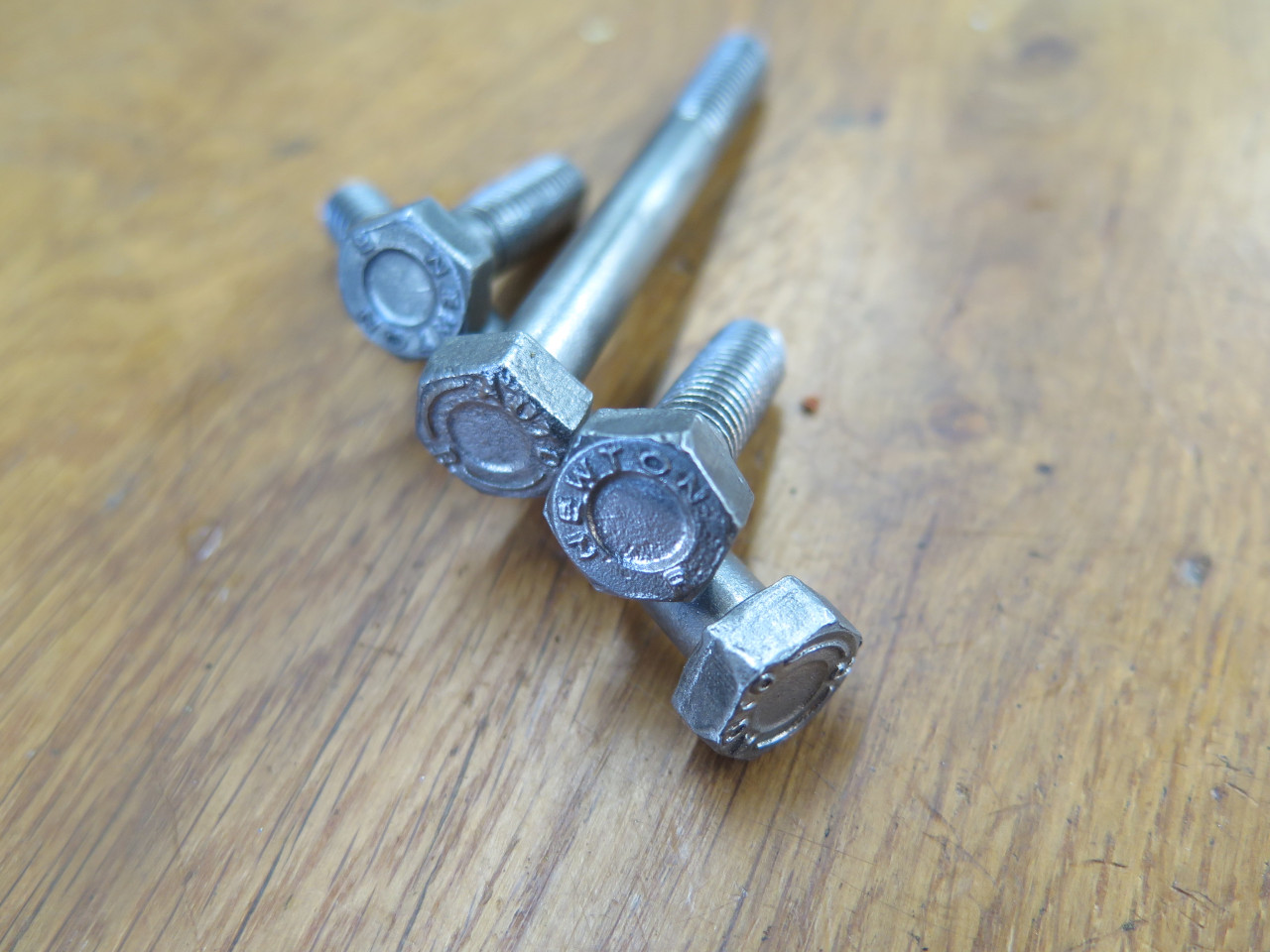
replate original fasteners when I can.
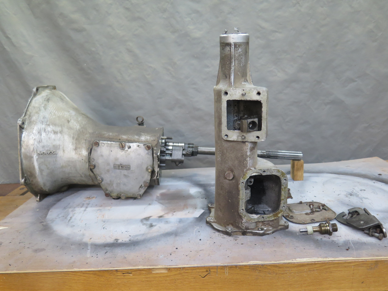
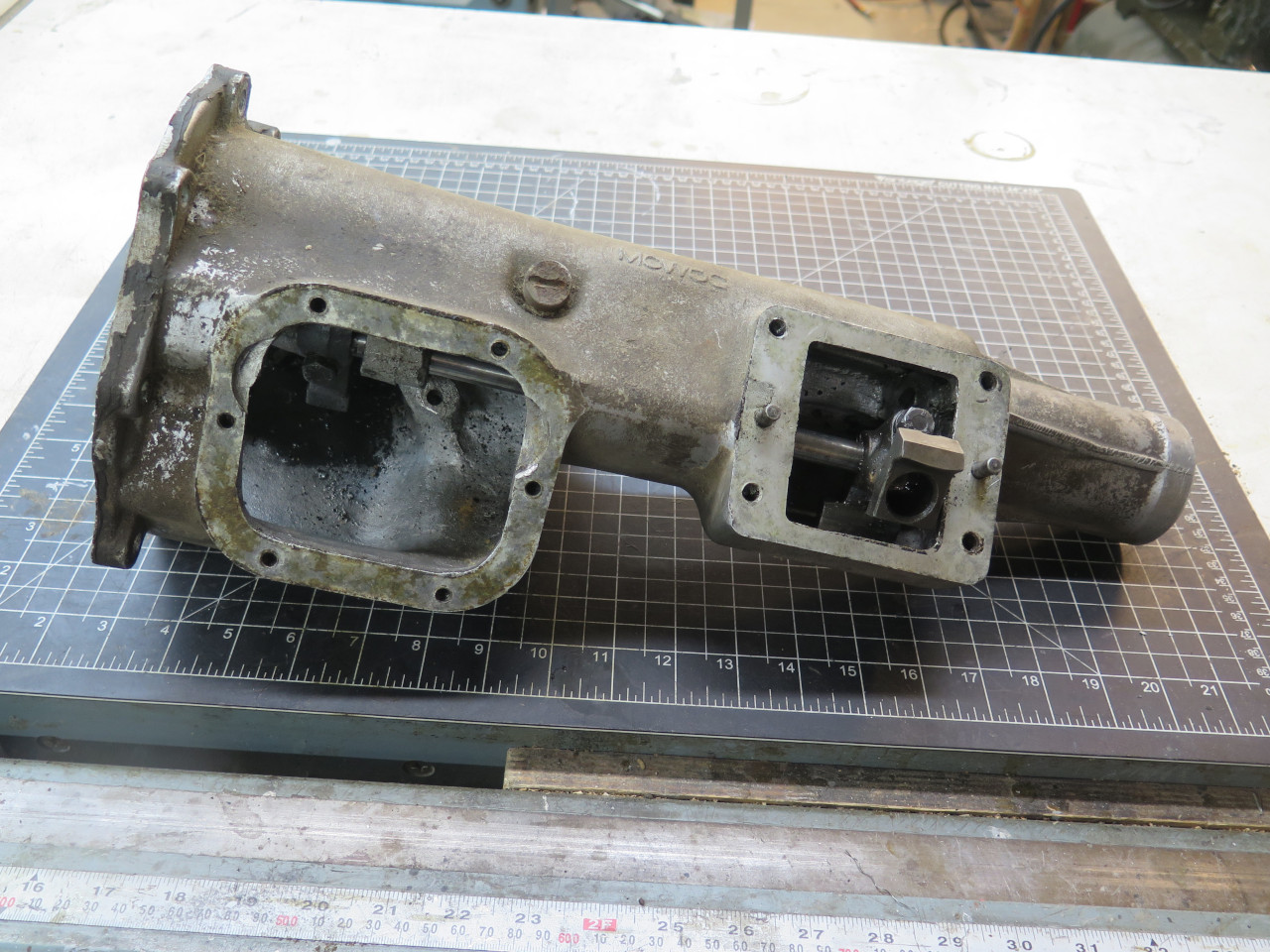
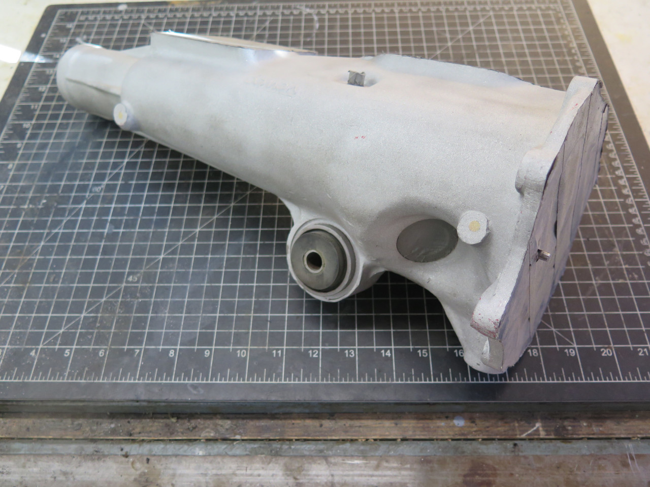
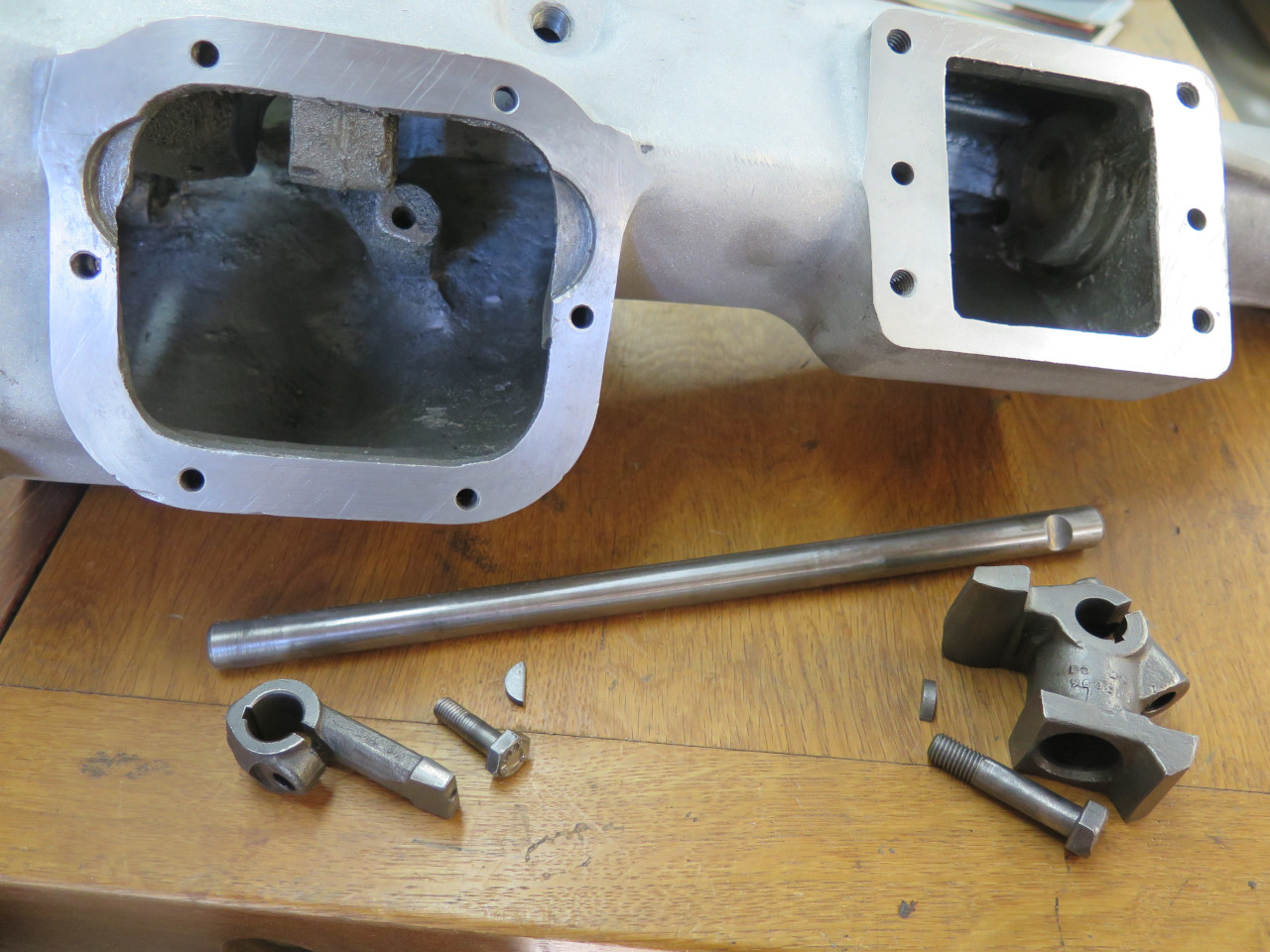
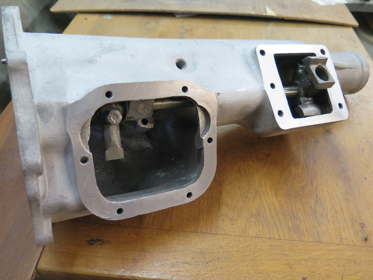
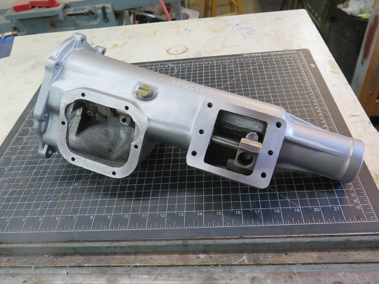
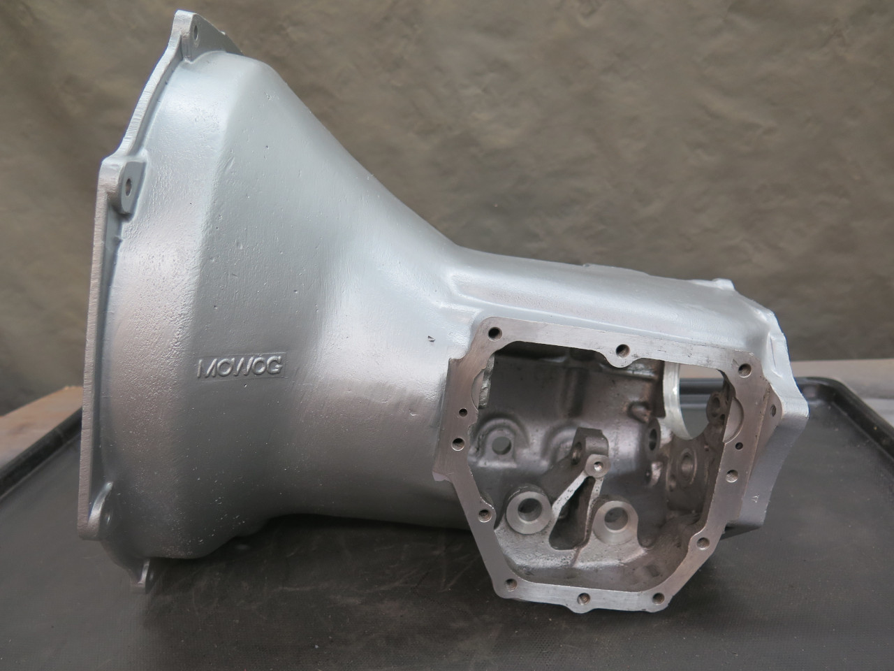
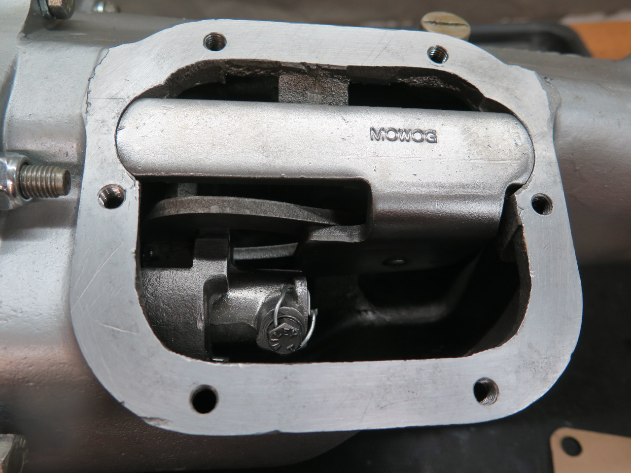
Rear Extension
The rear extension of the gearbox bolts to the back of the gear case,
provides access to much of the gear selection mechanism and the
speedometer drive, and holds the rear gearbox mount and the rear bushing
and oil seal. It also encloses a screw type oil pump on the
mainshaft for low pressure distributed lubrication of the gearbox.
Mine was appropriately grimy, but intact.
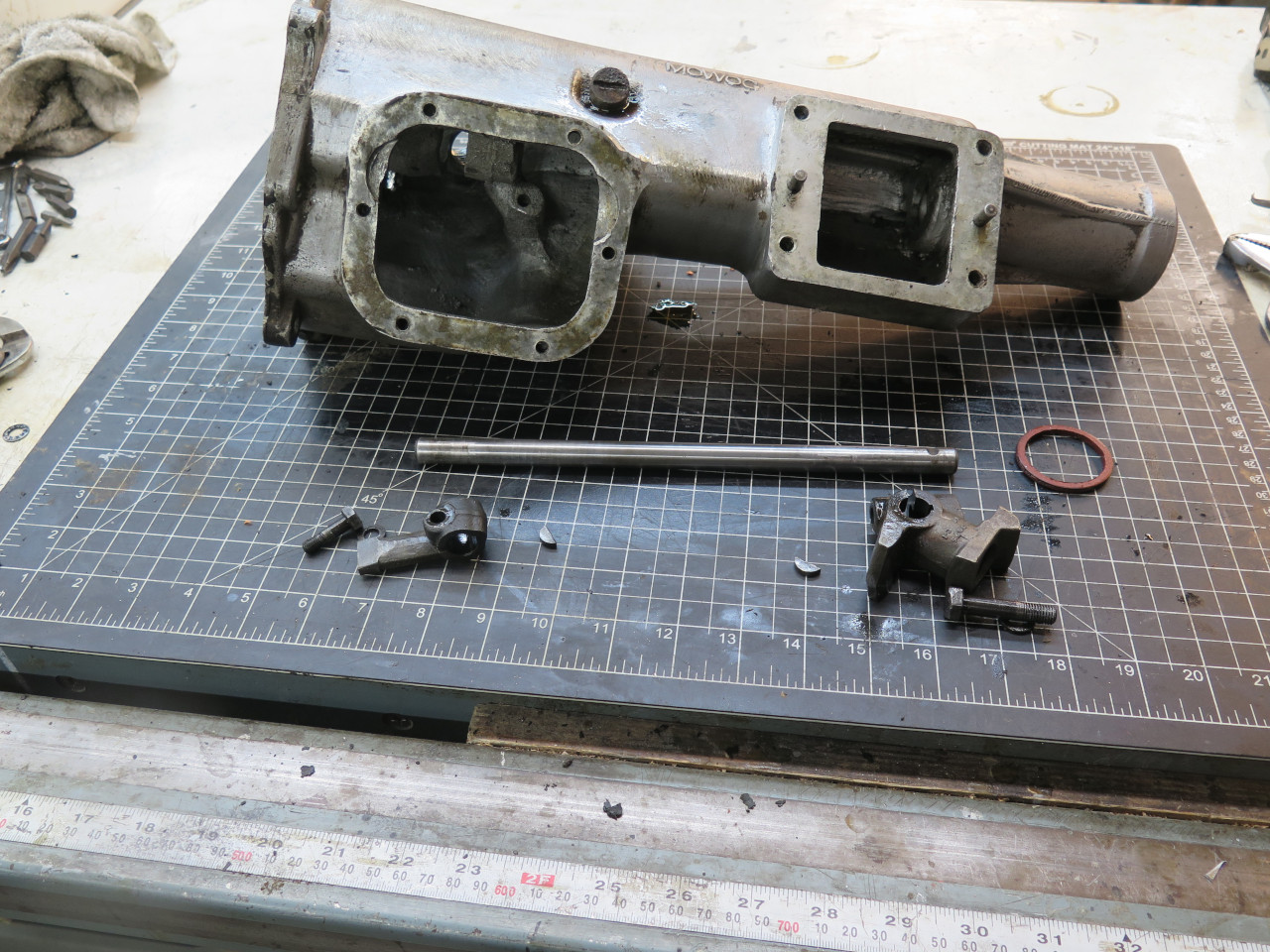
Inside is a shaft that connects the shift lever to the gear selection parts of the gear case.
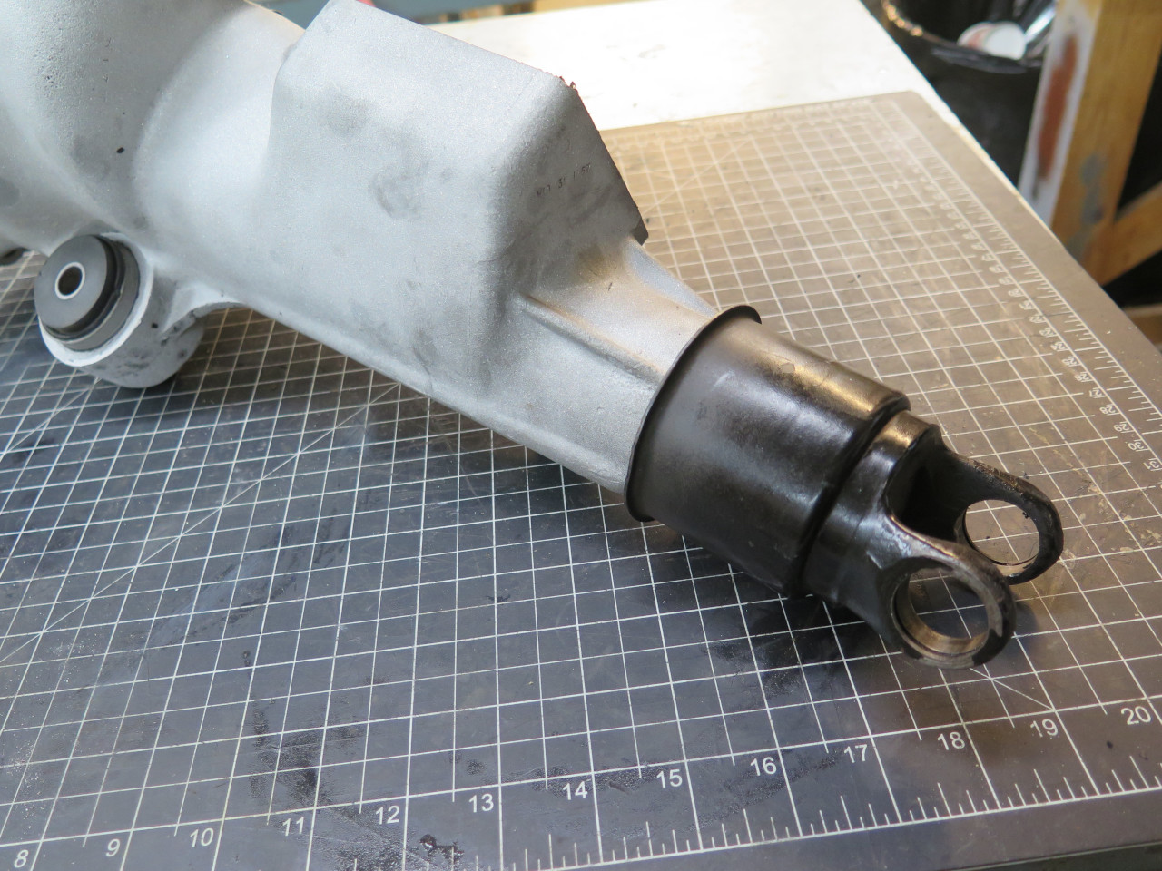
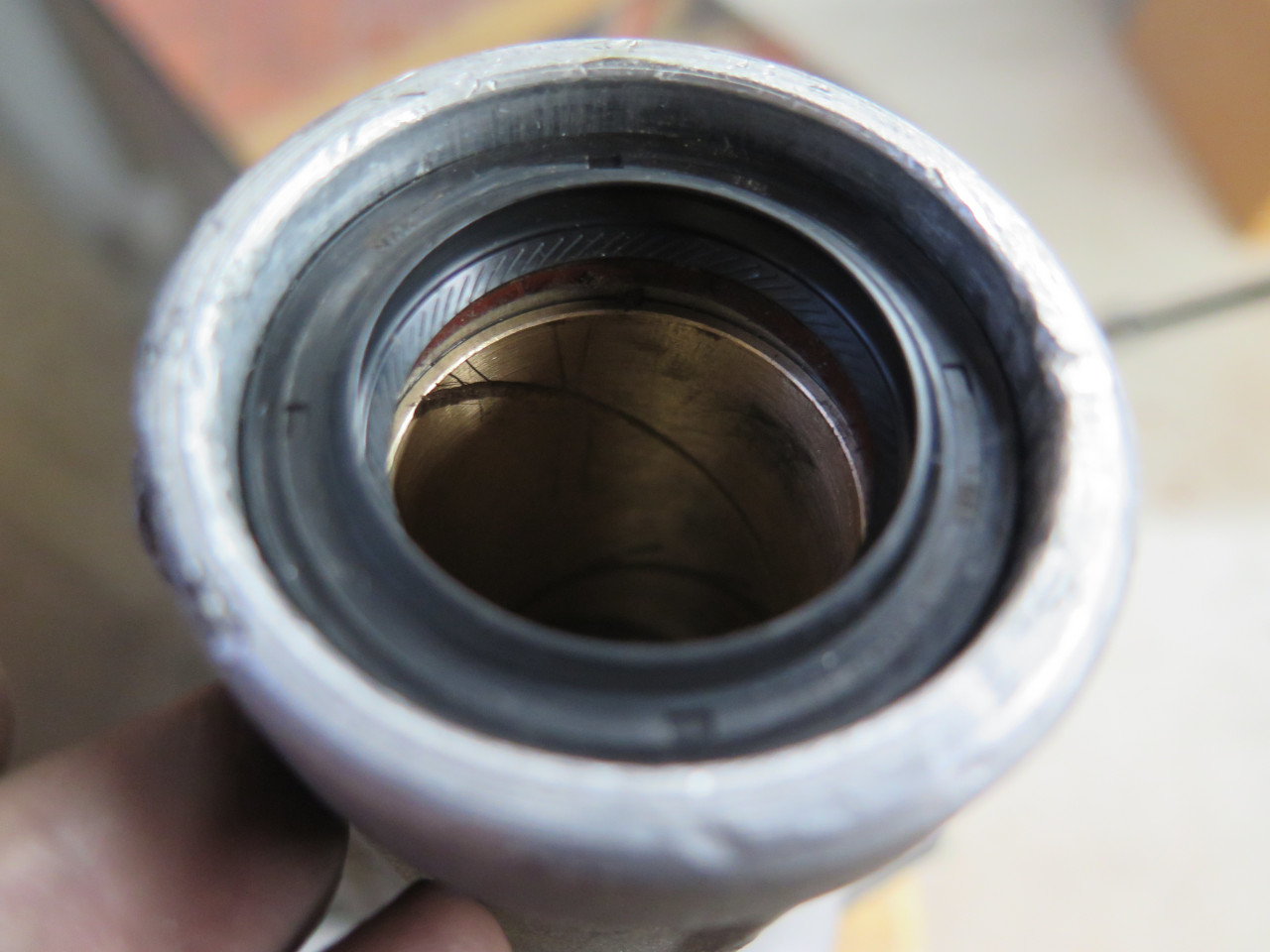
Though the main casting and the shaft assembly seemed to be in good
condition, my main concern was with the rear bushing. Later
versions of this gearbox apparently had a ball bearing at the rear, but
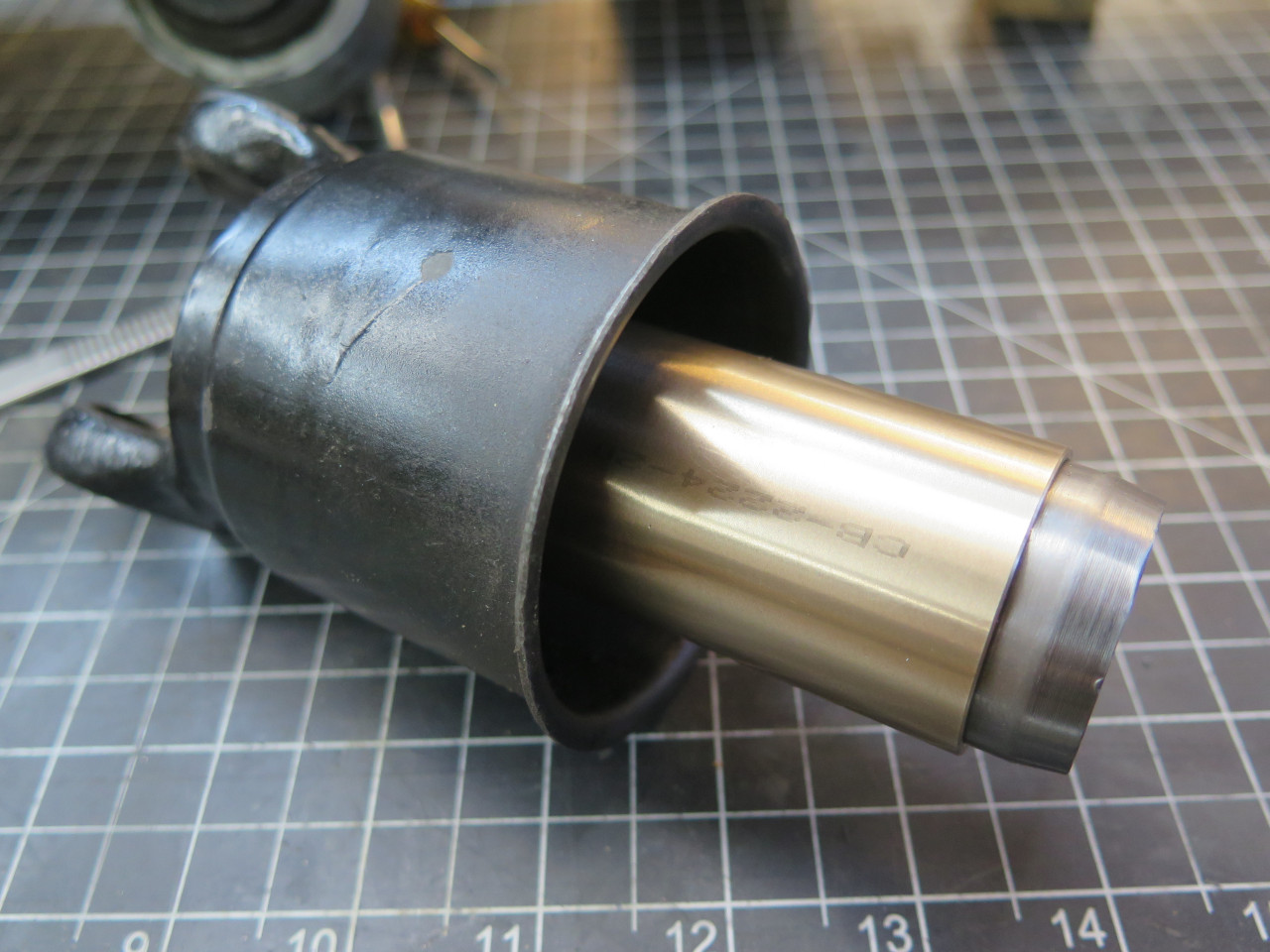
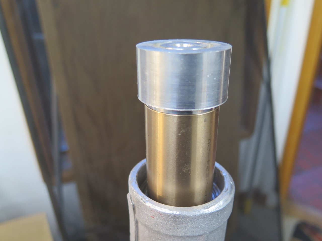
this one has only a bronze bushing. The gearbox mainshaft doesn't
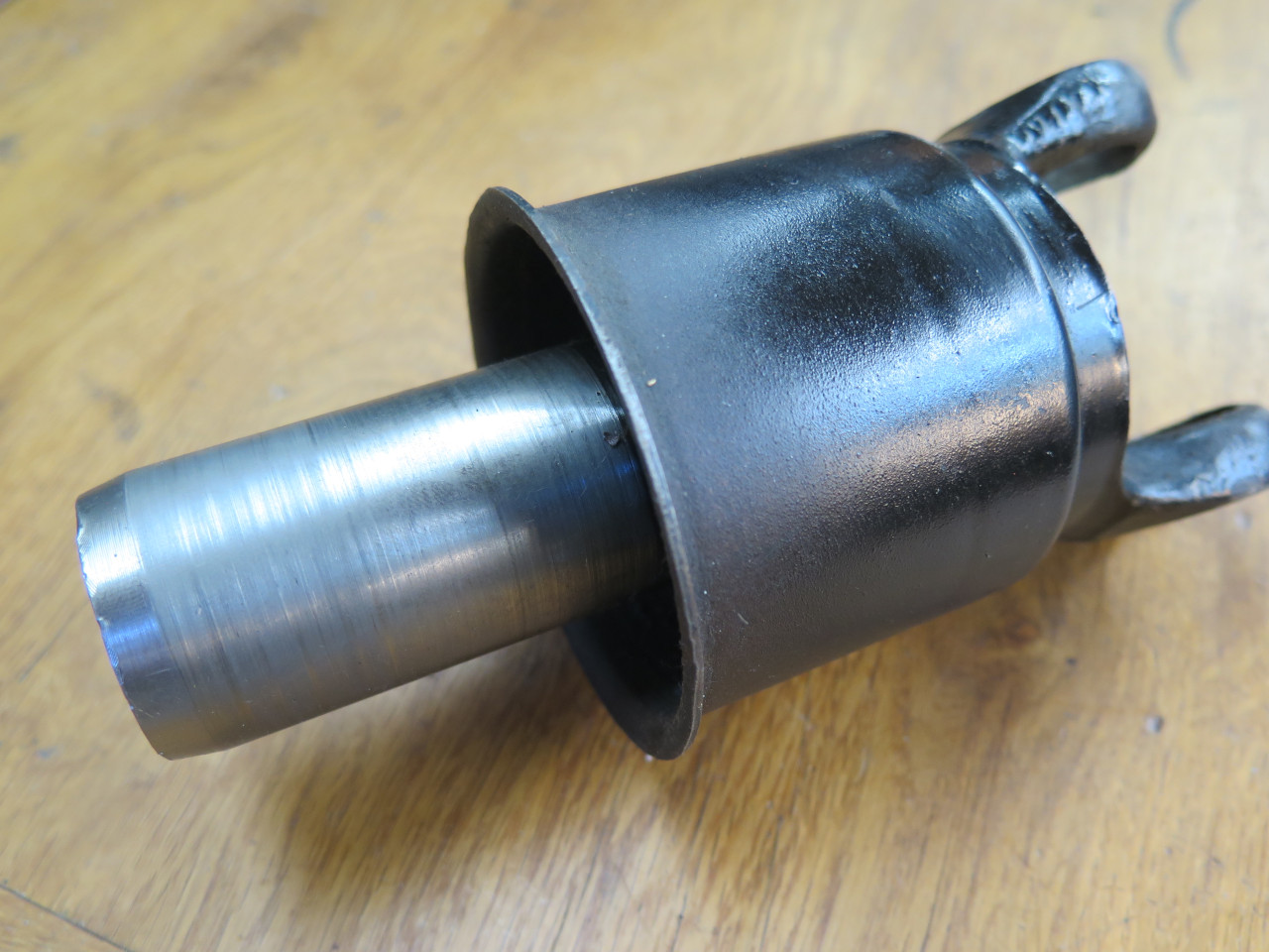
ride directly in this bushing, but is splined into a barrel on the front
propeller shaft yoke, and it's this barrel that rides in the bushing.
The yoke had nearly 0.010" of play. I'm not sure if there is a
published spec for this, but that seemed like a lot. I'd prefer
something around 0.002" or 0.003".
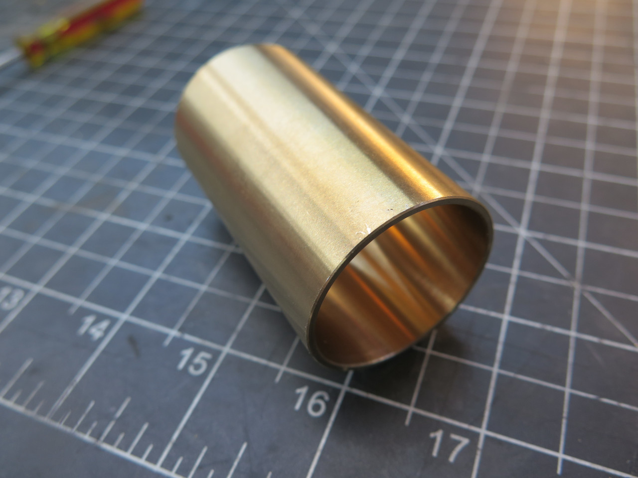
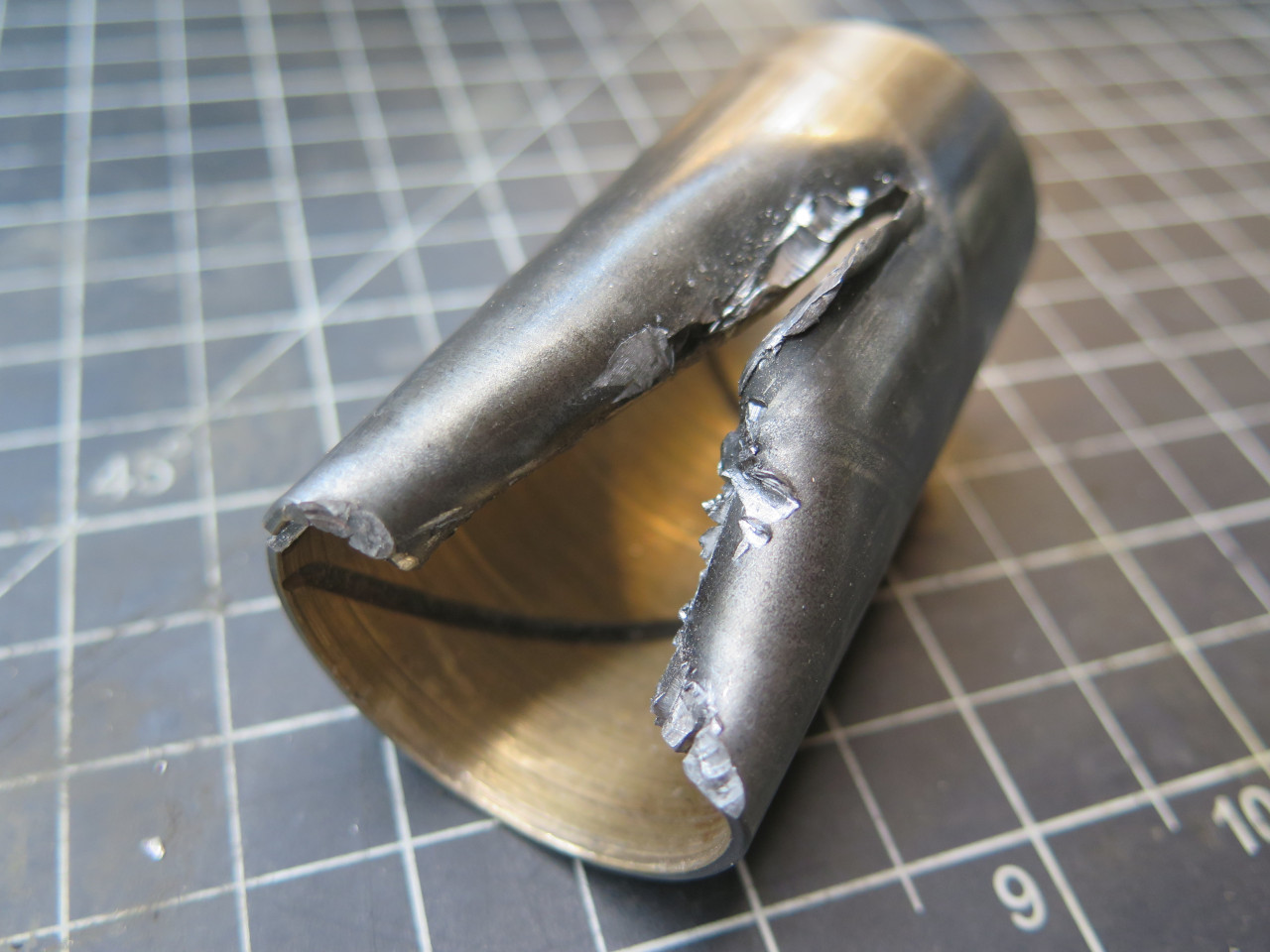
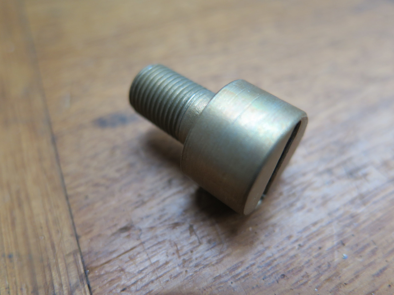
The bushing is apparently not available any more from LBC suppliers, but
its dimensions are pretty standard: 1.500" OD x 1.375" ID x 2.75"
L. I was ale to find a close match from an industrial
supplier. The OD and ID were correct, but it was only 2.5 inches
long. I considered that close enough.
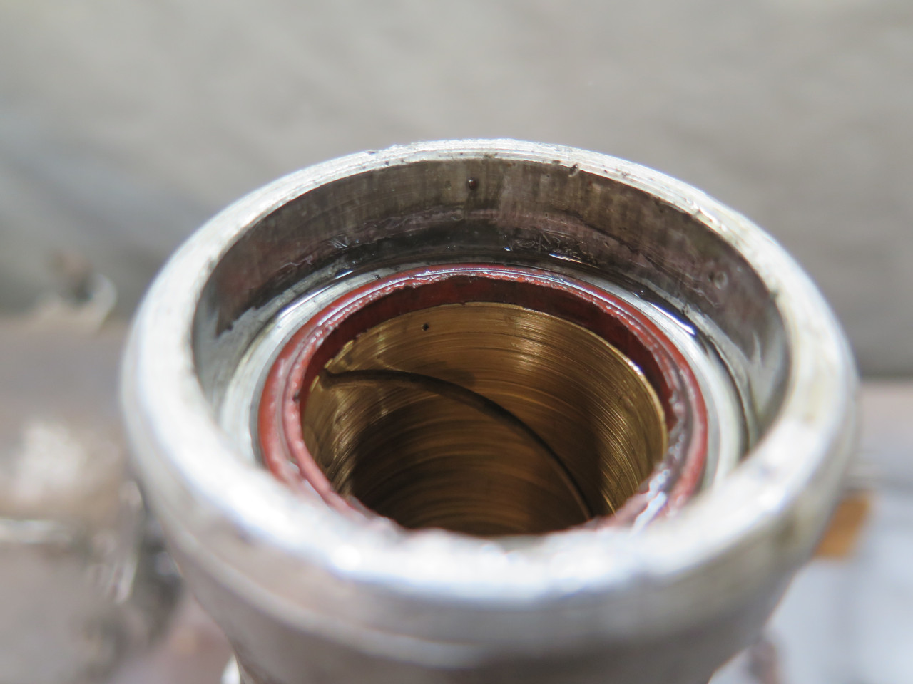
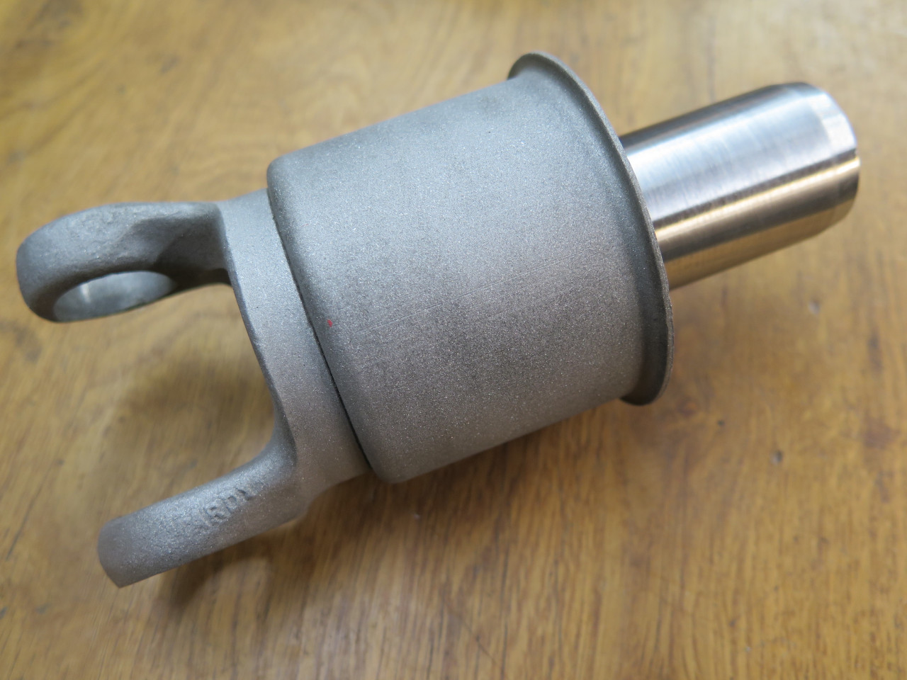
Testing the new bush on the yoke, it was very tight. I had to hone it to have a nice slip fit.
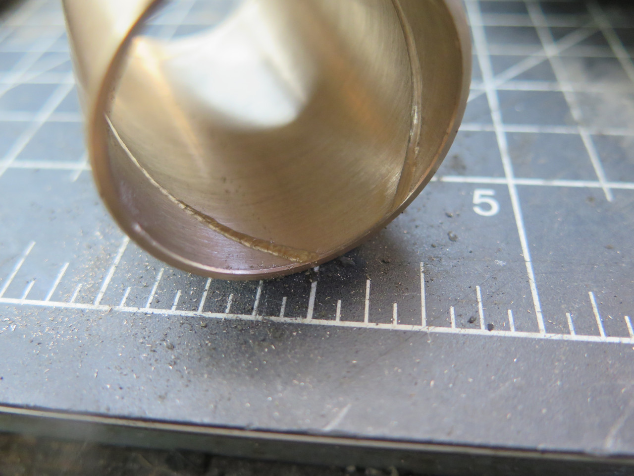
Then, there was the problem of lubrication. The original bush had
spiral oil grooves to distribute lubrication. They seemed
important.
Avoiding long winded and gory details, I was finally able to cut spiral grooves.
Then it was just a matter os swapping the bushes. I fashioned a puller for the old bush.
The puller was elegant and based on mechanically sound principles.
But it didn't work. I tightened that nut until I feared I was
going to break something.
I finally resorted to cave man technology. Luckily, there was a
small oil gutter on the bottom side of the bore, so I could saw and
chisel the bush without doing any damage to the bore.
Before beginning reconstruction, I took a minute to mask the openings
and give the case a light blast to make it more pleasant to look
at. The rubber gearbox mount (a 1970s replacement) looked and felt
essentially new, so I didn't even remove it.
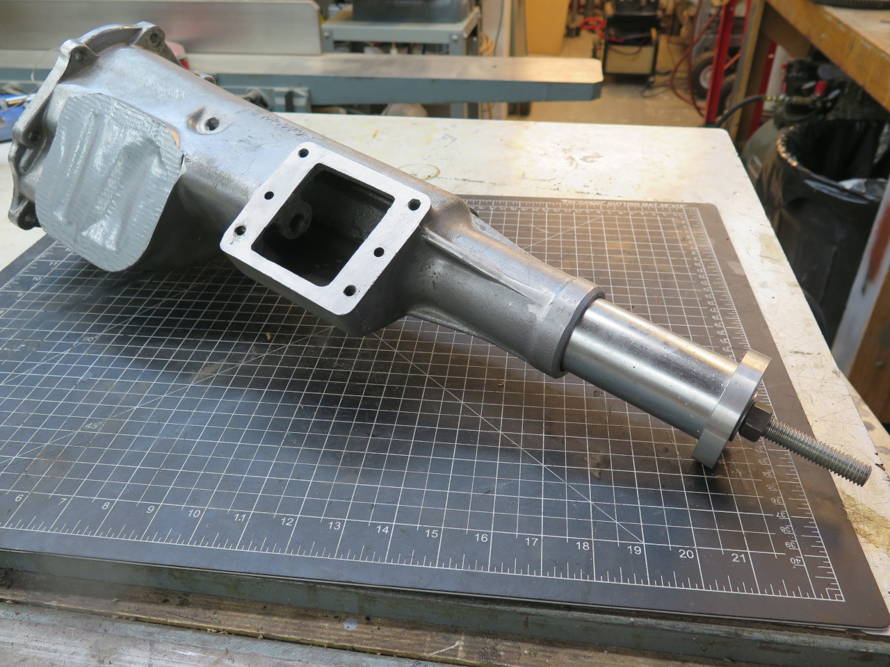
Then installed the new bush. The casting was too tall for my
press, so I had to fall back to a more Neanderthal hammer. The
bush went home reluctantly, but peacefully. I centered the new
shorter bush on the old bush's position, leaving a 1/8" shortfall at
each end.
Then, trying the yoke again, I found it pretty tight. This wasn't
unexpected, so another few minutes of honing got me a very nice fit.
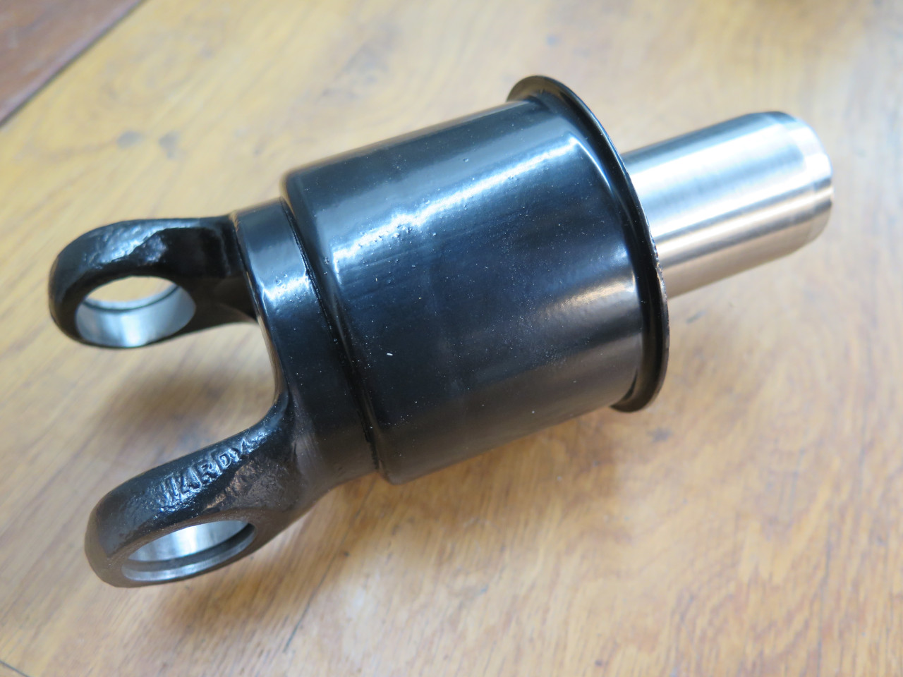
This seemed like a good time to blast and powder coat the yoke.
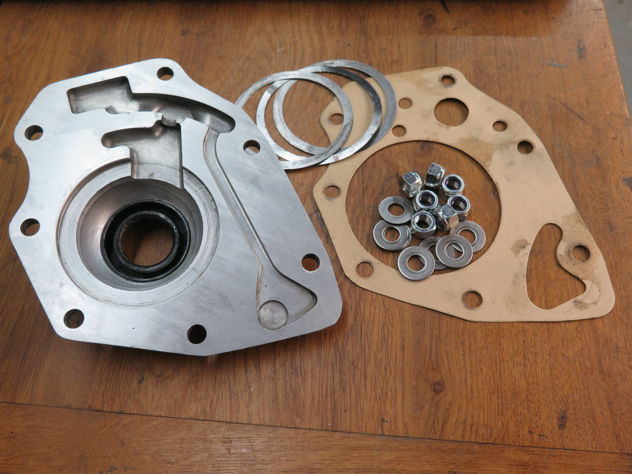
Reinstalled the shaft with its arms...
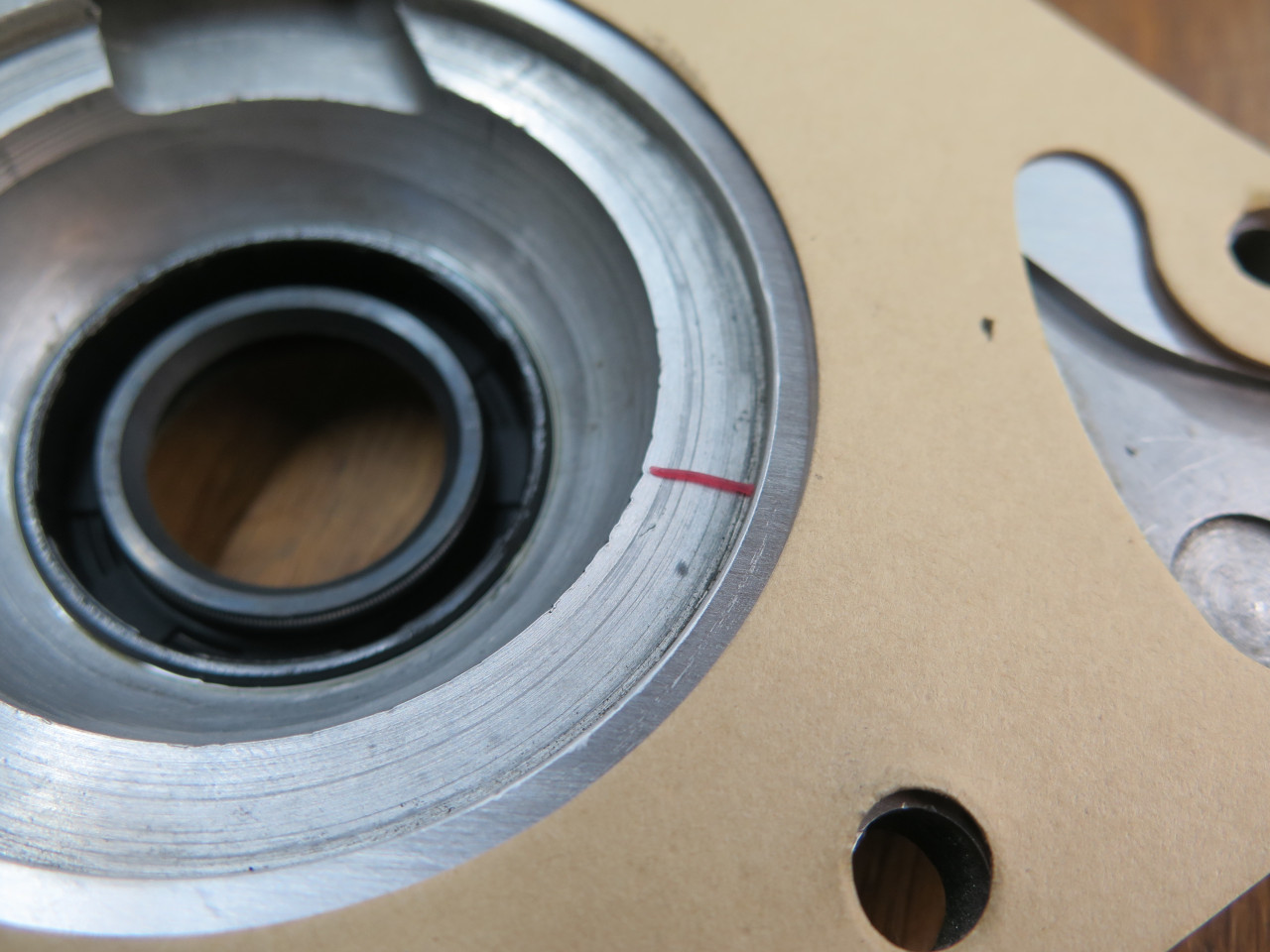
...and installed a new rear oil seal. I'm not sure the purpose of
the fiber washer, but it came out of there, so I put it back in.
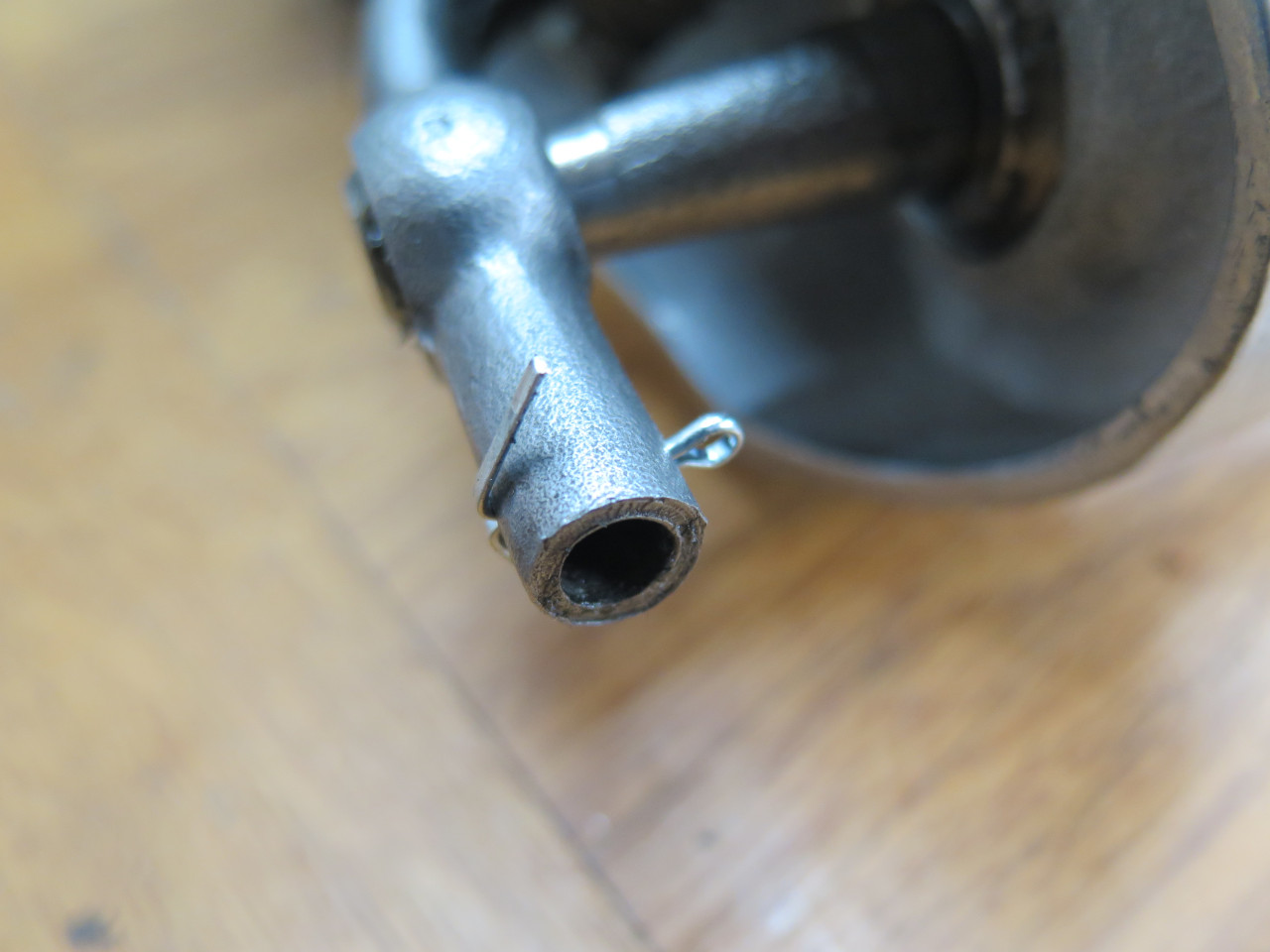
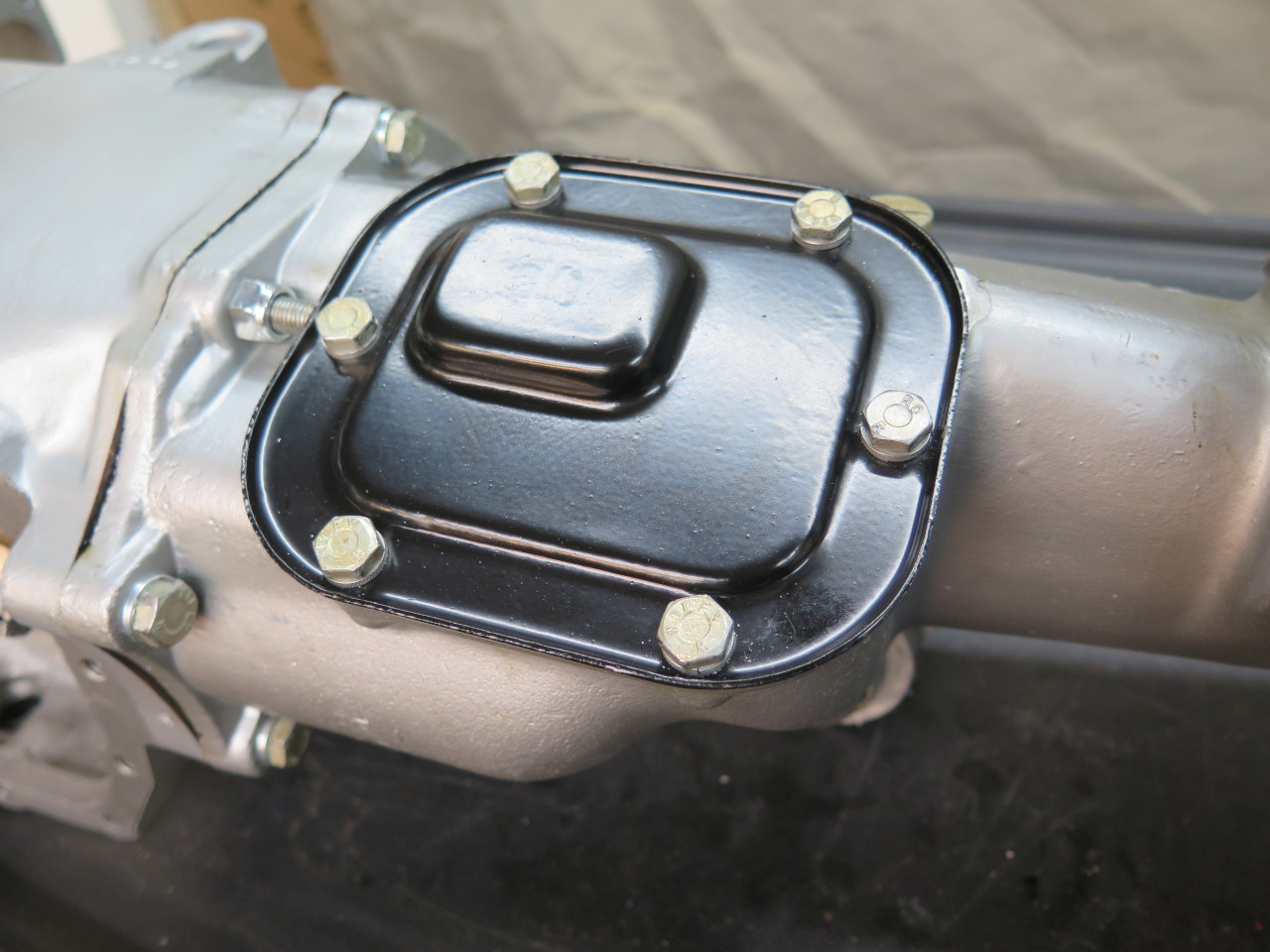
This rear extension also has a small air vent on top. The interior
of sealed cases like this need to be vented because with rising inside
temperature, he air expands and increases internal pressure, and this
pressure can force oil past seals. A vent serves to equalize the
internal pressure.
The vent was a simple little device with a cap to help prevent any
foreign material from entering, but it had no filtering
capability. Modern vents often have some provision for filtering
air that enters the case.
So of course, I went looking for one. The problem came when I
realized that what I thought was probably a 1/8" pipe thread actually
turned out to be a rather odd 3/8-28 thread. It's a standard
thread, but not very common, and I found no suitable vents with that
thread.
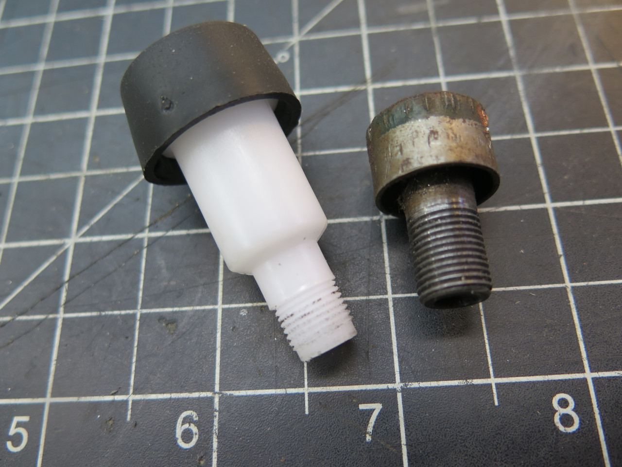
I ordered a vent from one of our LBC suppliers. What came was this gangly looking plastic thing.
It fit but was also unfiltered. I opted to fix up my more stout original.
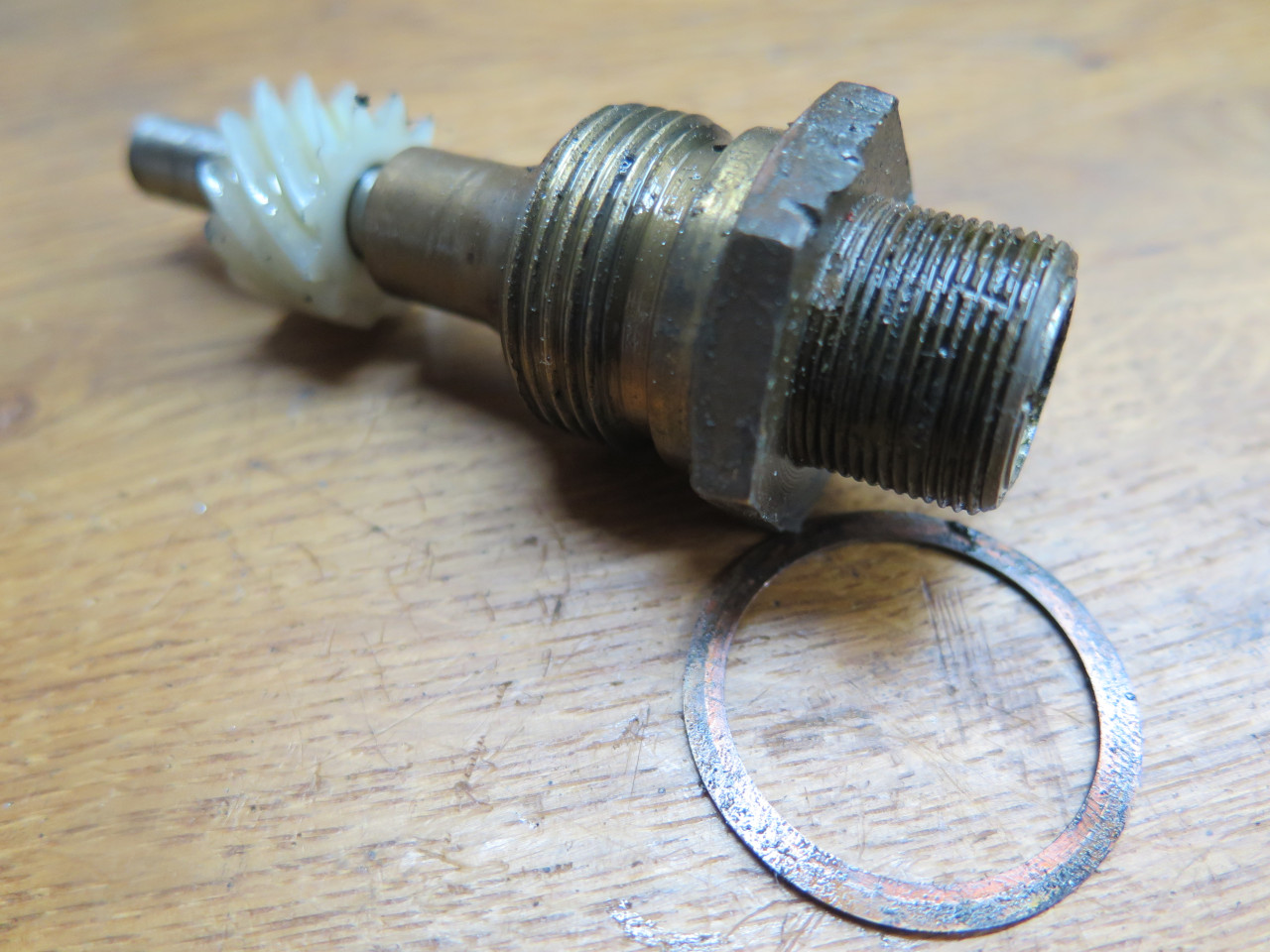
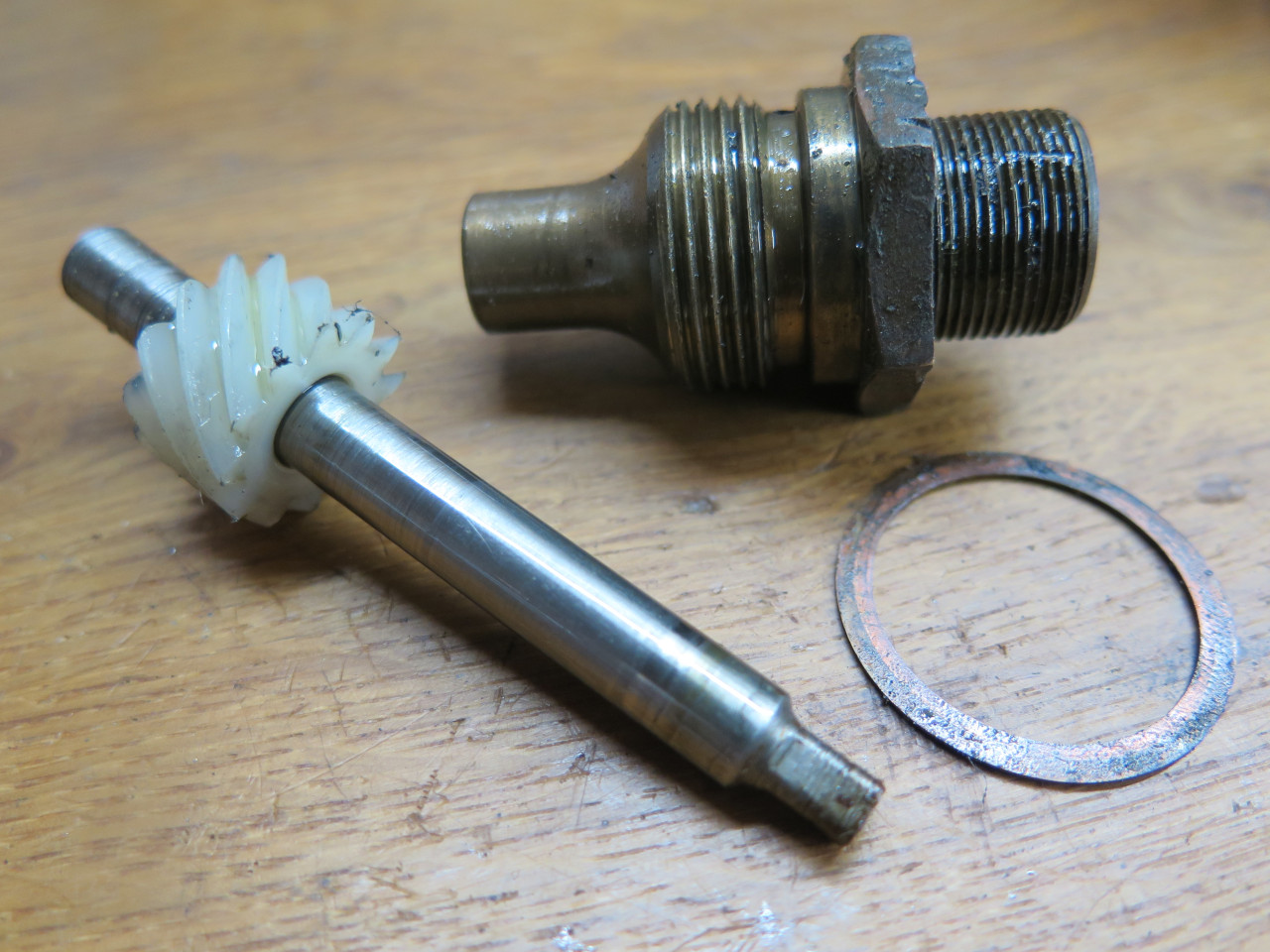
Next up was the speedometer drive. Its gear mates with one on the mainshaft.
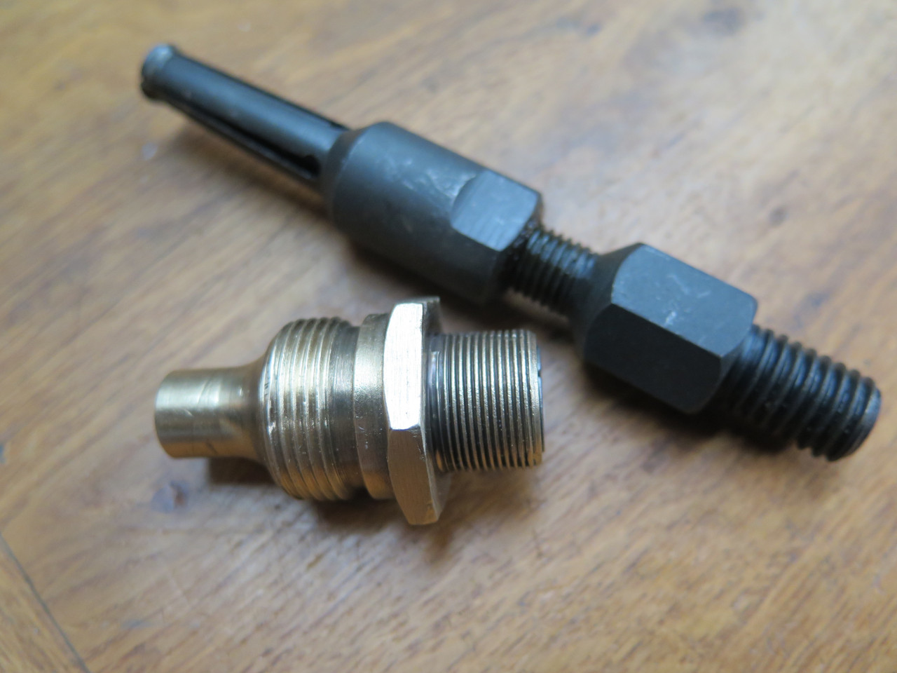
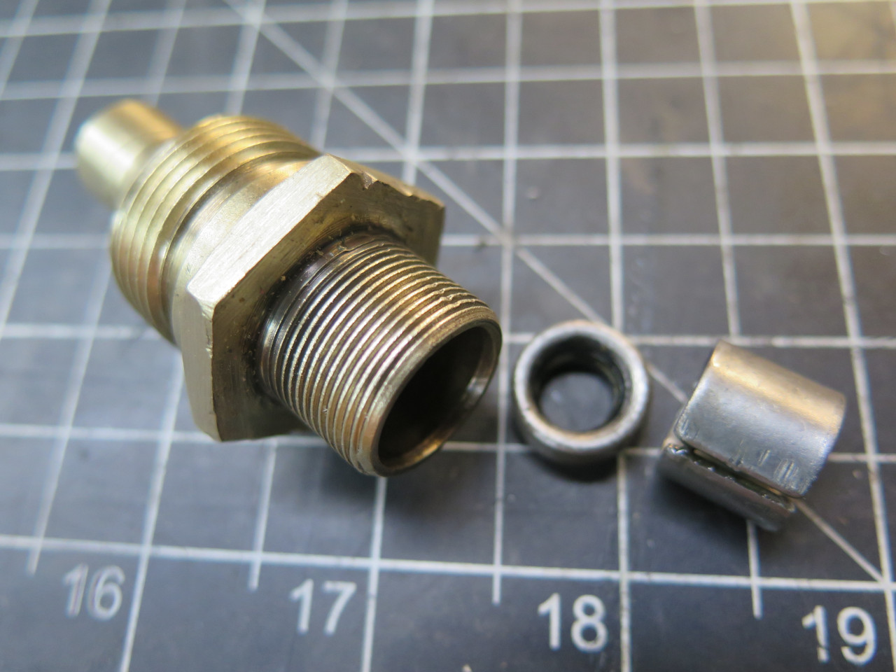
The spindle was still a nice fit in the brass housing, but there is an
oil seal that needed to be replaced. The tool is a blind bush
puller. It got the metal retainer out, but the seal had to be
driven out from the other end.
New seal, and freshly annealed copper washer.
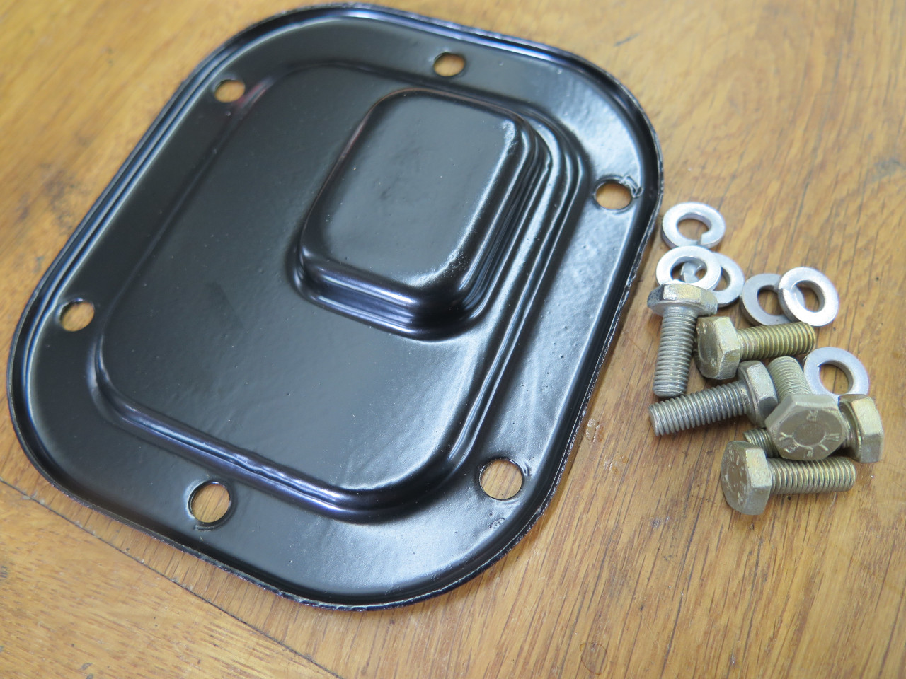
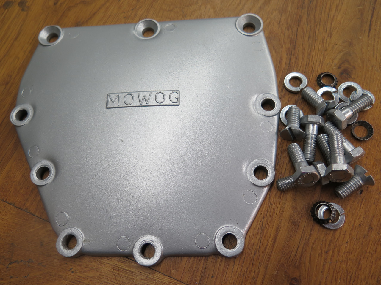
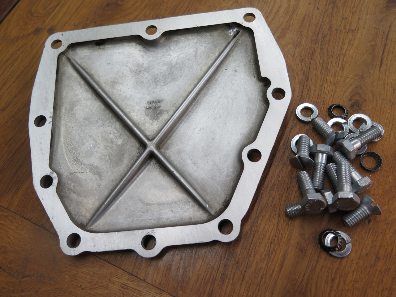
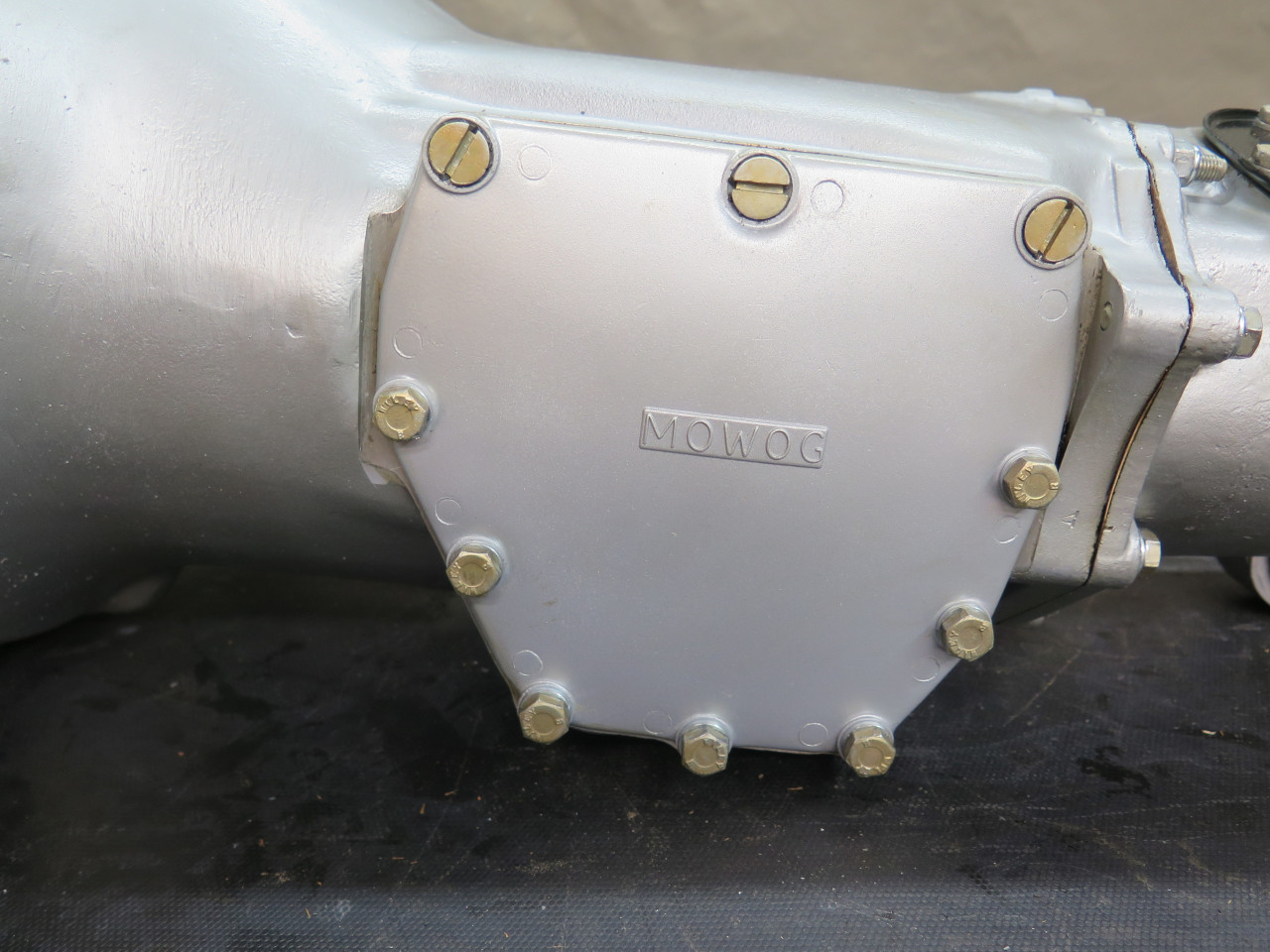
Access cover plate was powder coated and the original bolts replated.
I've been given to painting or powder coating my aluminum castings
lately. No real functional purpose, but it makes them more
pleasant to handle, and it makes me happy. Mating surfaces aren't
painted, but linished flat if possible.
A couple of alignment pins accurately locate the remote tower to the extension.
So far, so good.
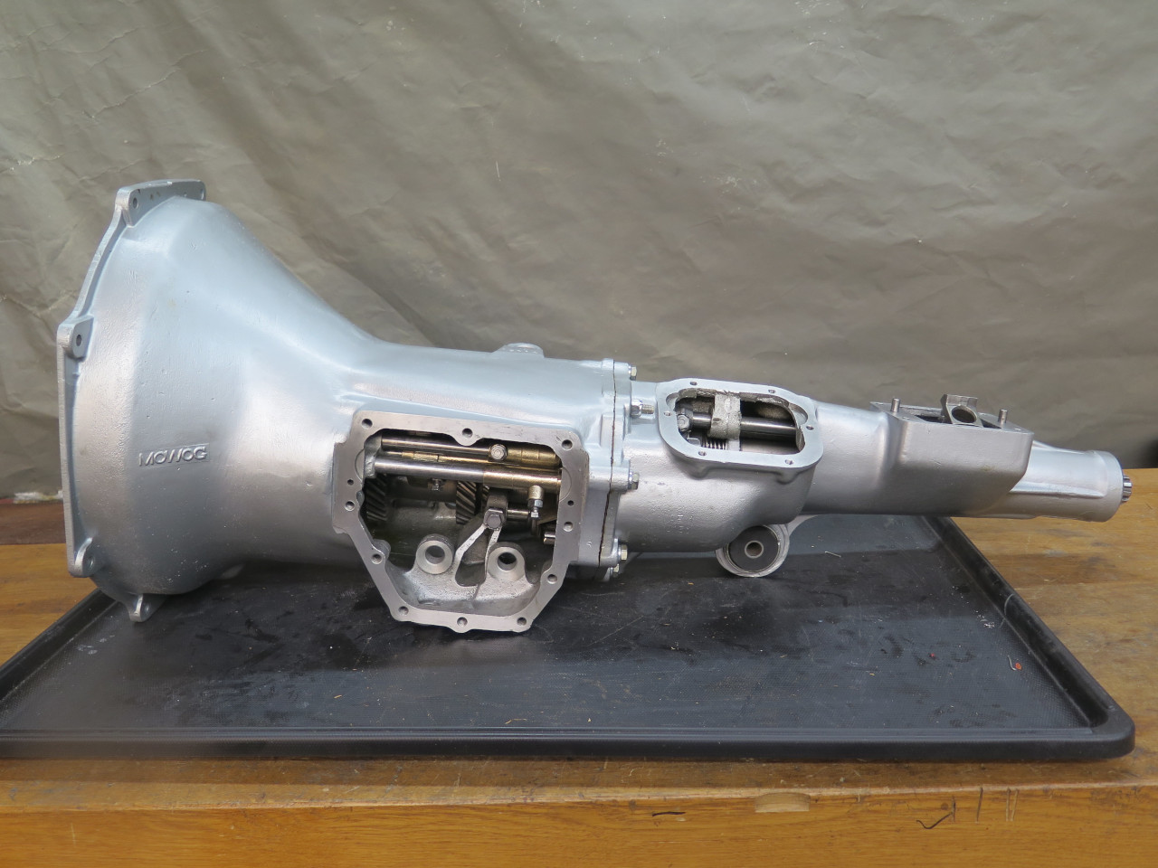
Gear Case
This is a pretty conventional four speed gear box. The fact that
first gear is not synchronized simplifies it somewhat. The gear
case is integral with the bell housing.
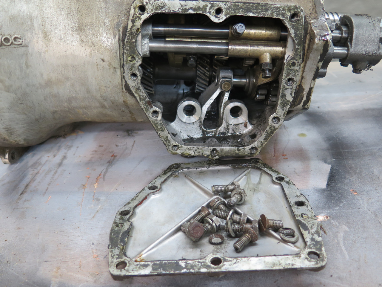
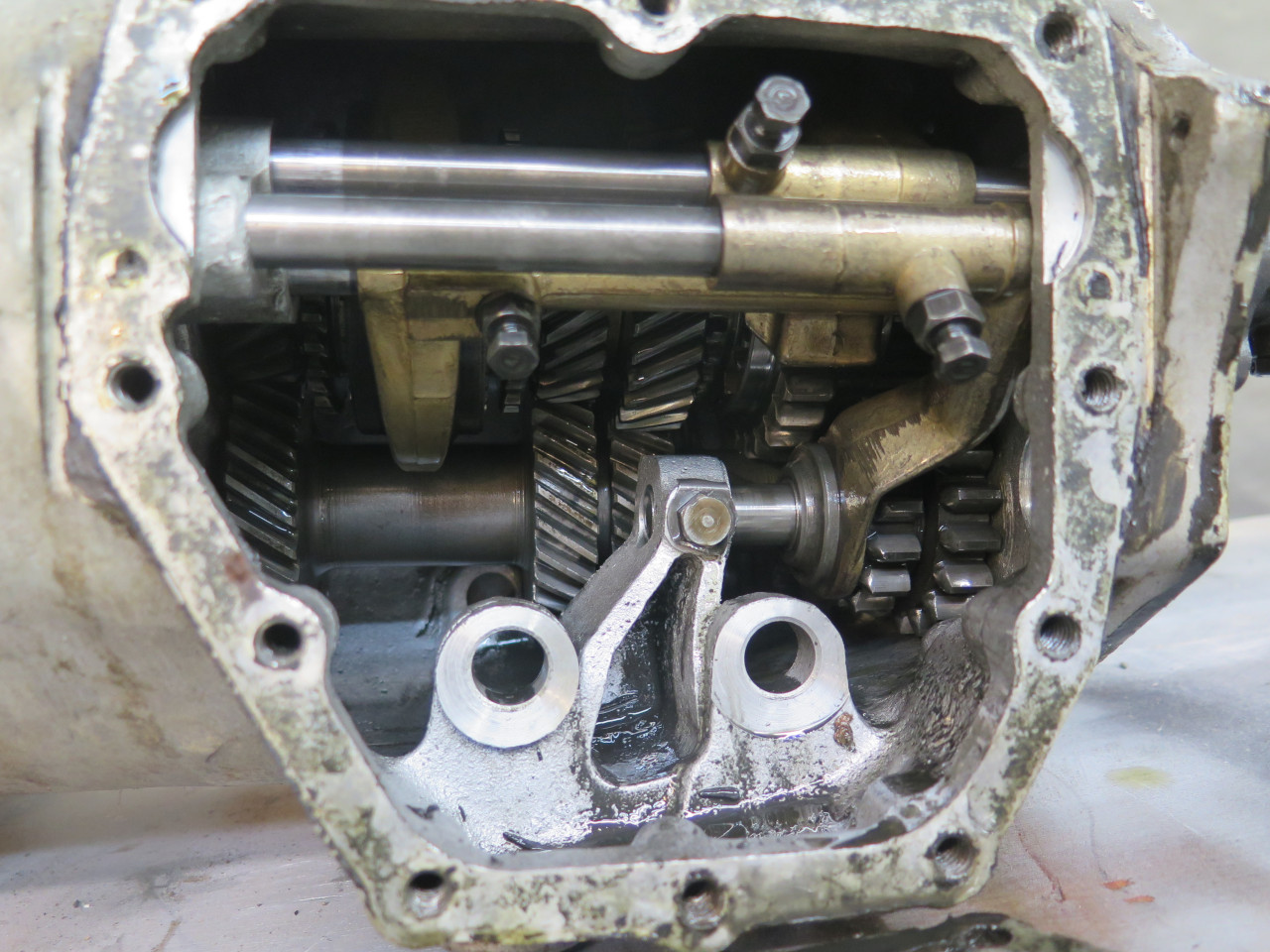
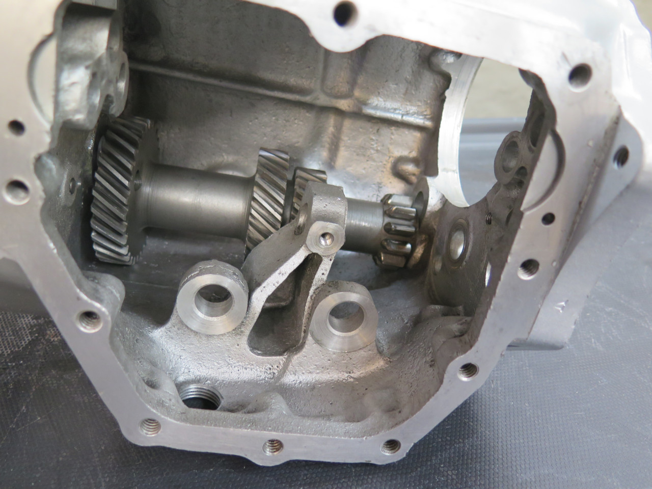
Removing the access cover reveals the guts. Gear selector mechanism in front, gears in back.
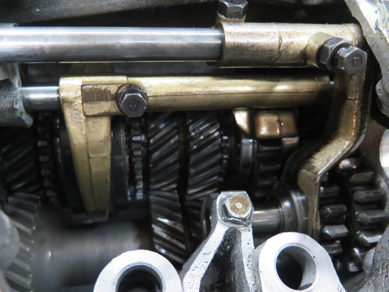
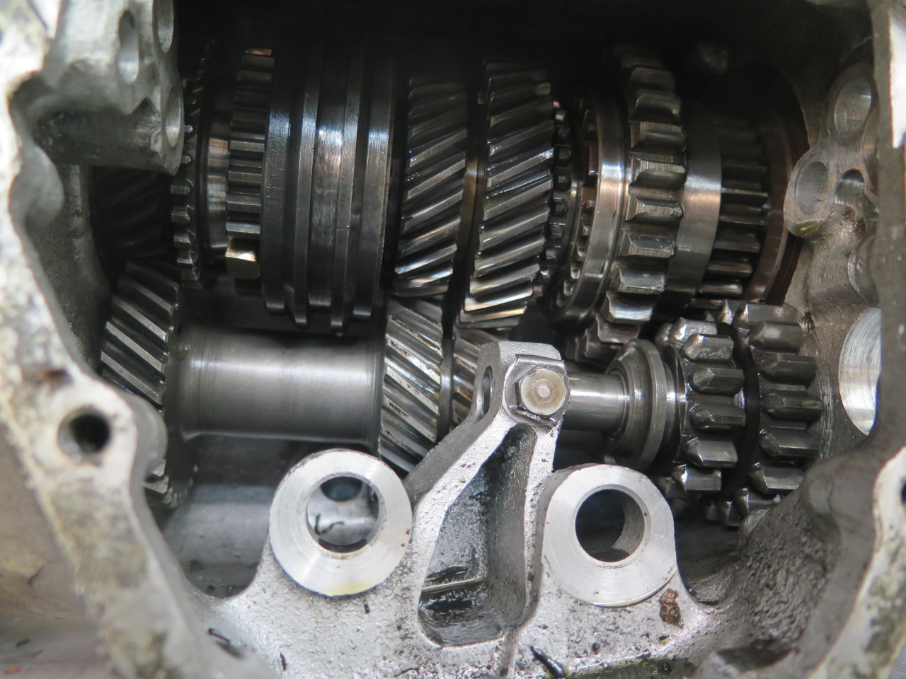
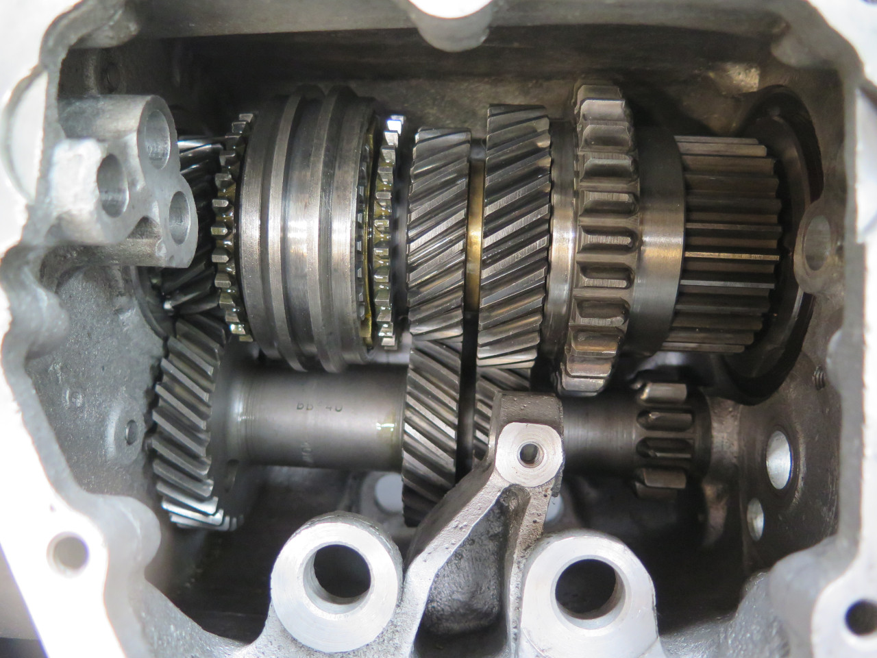
Removing the gear selection stuff allows a better view of the gear
clusters. Input and mainshaft and gears above, and layshaft and
gears below. Reverse gear is right front. Interesting that the
first gear uses straight cut gears rather than the helical cut used for
other gears.
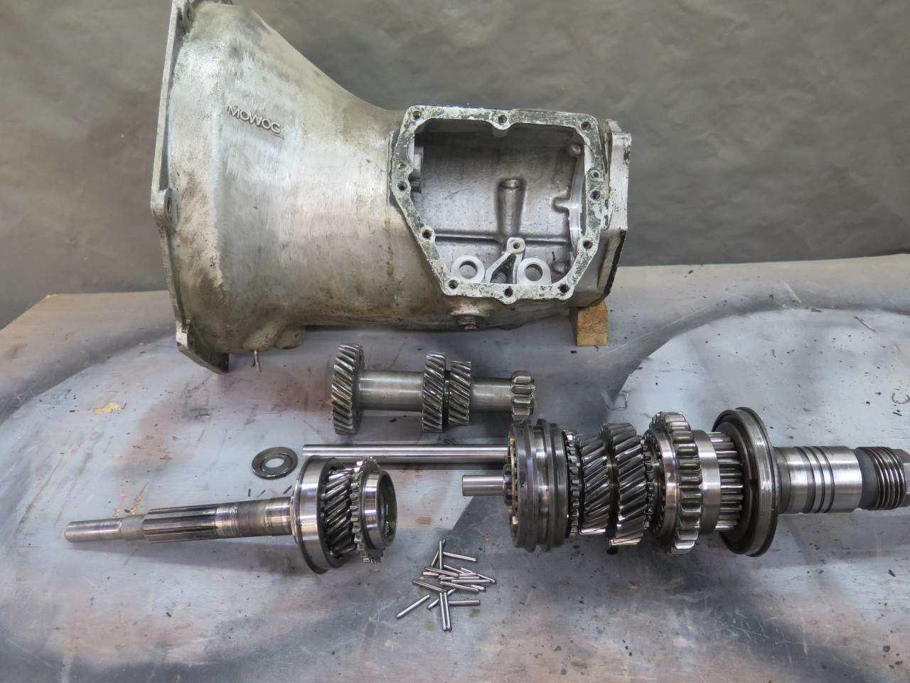
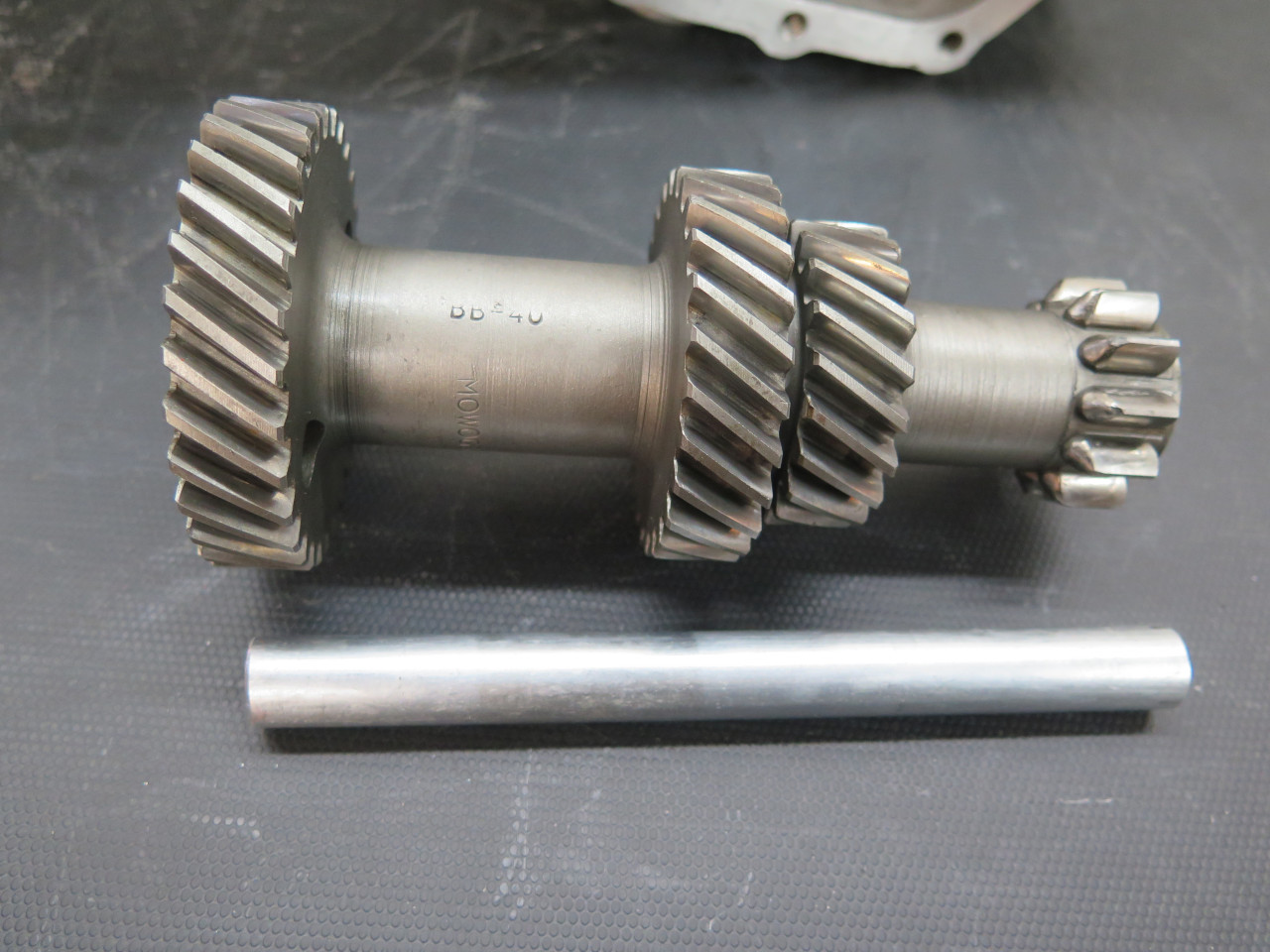
Everything out of the case. Input (sometimes called "first
motion") shaft on the left, mainshaft (sometimes called "third motion")
on the right, layshaft behind. I guess the layshaft would then be
the "second motion" shaft?
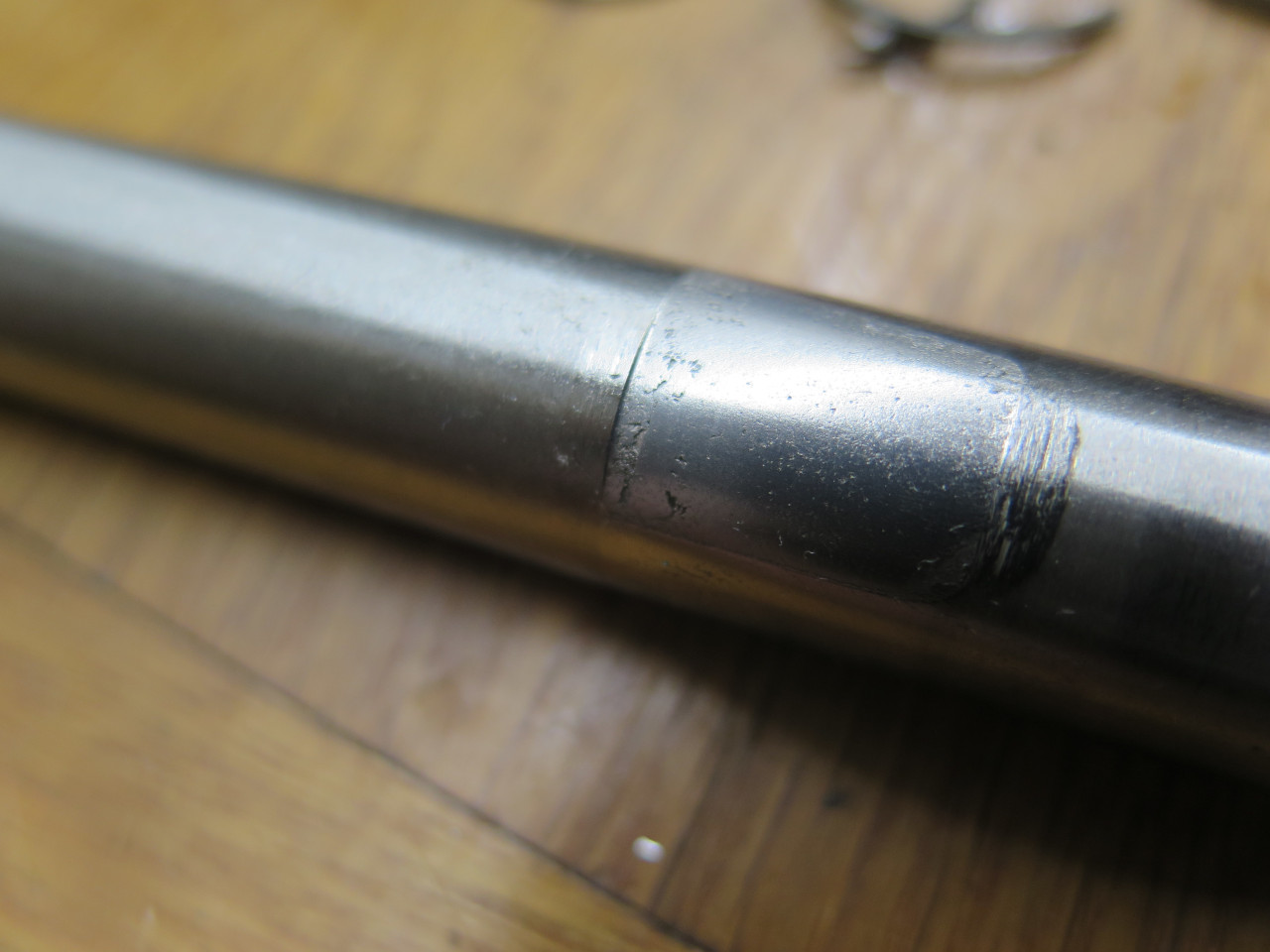
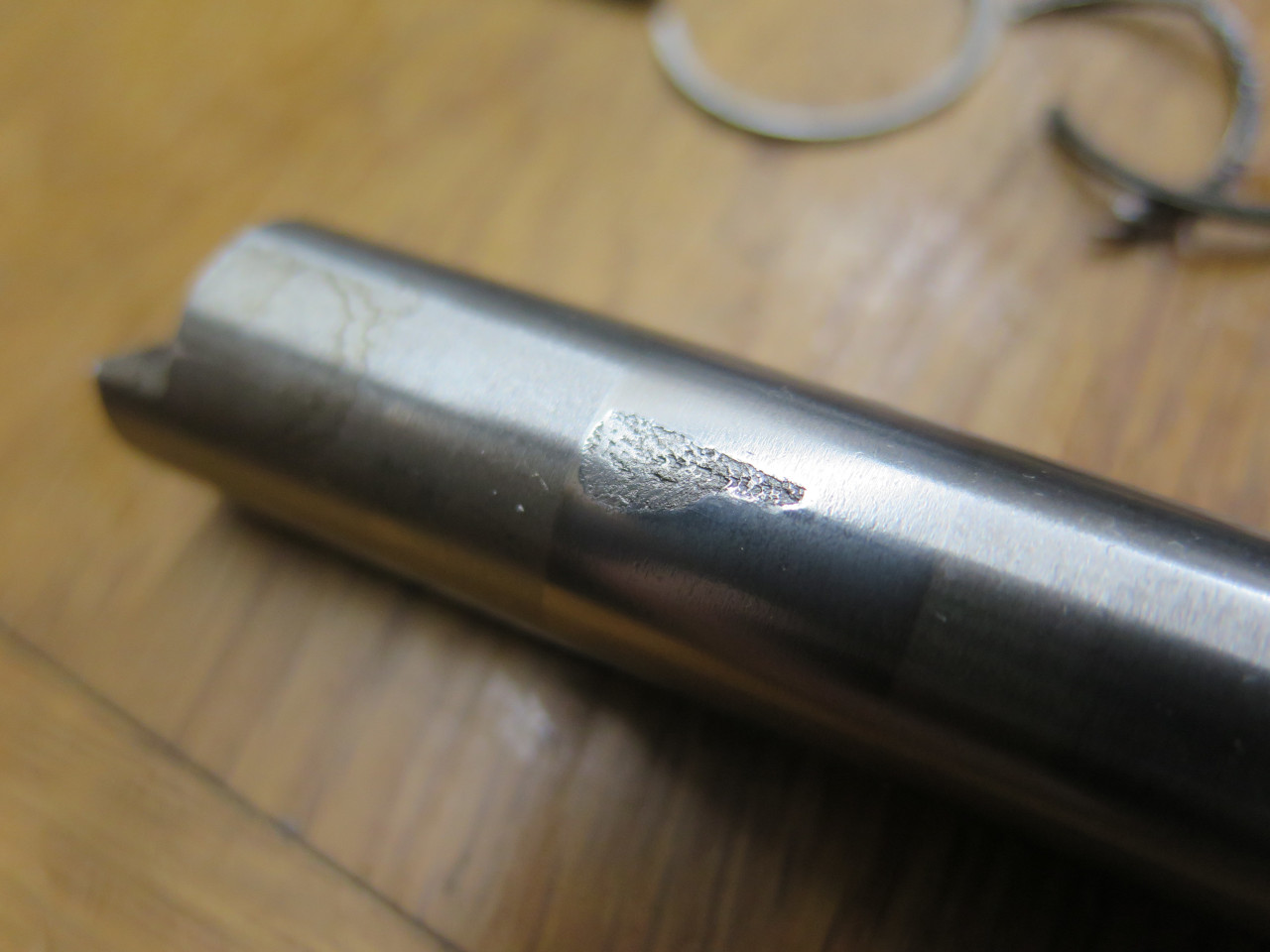
I inspected the layshaft parts first. The shaft itself had some
clear wear at one end, and what looked like galling at the other.
This meant a new layshaft and bearings. Before removing the old
bearings, I re-installed the layshaft parts into the empty case to
measure the end float, which was too big at about 0.007". A new,
thicker small end thrust washer brought that down to about 0.003", right
on target.
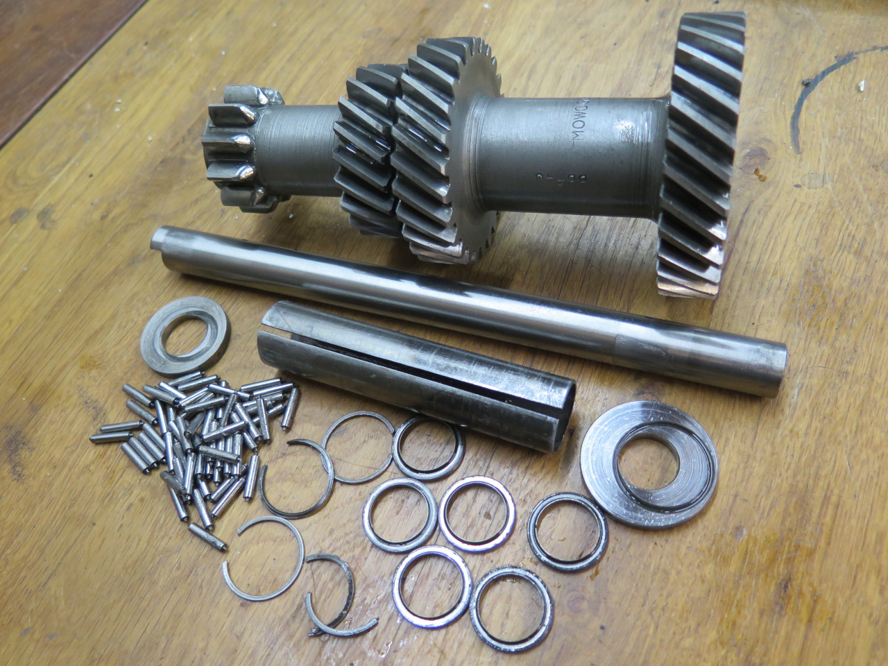
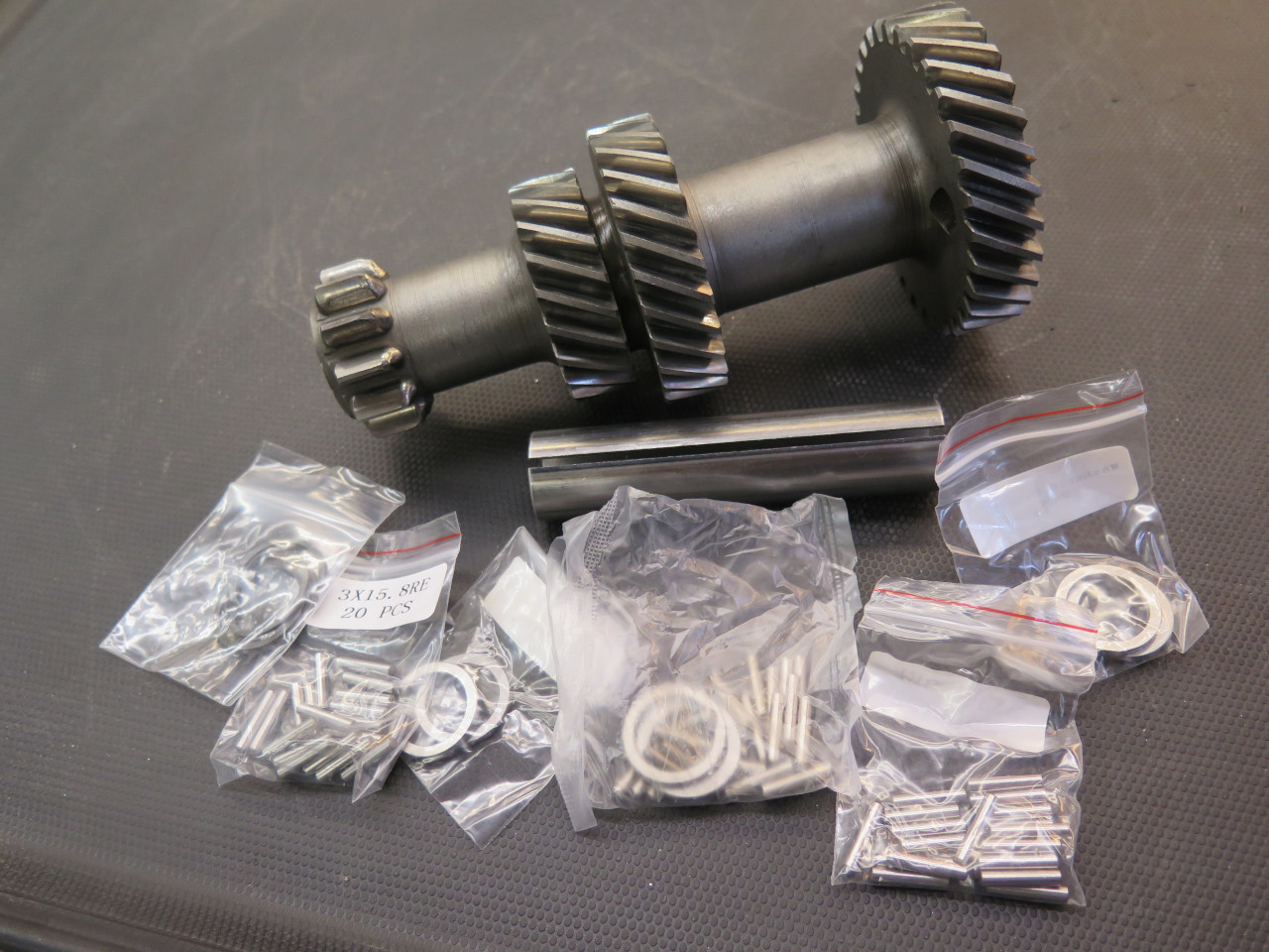
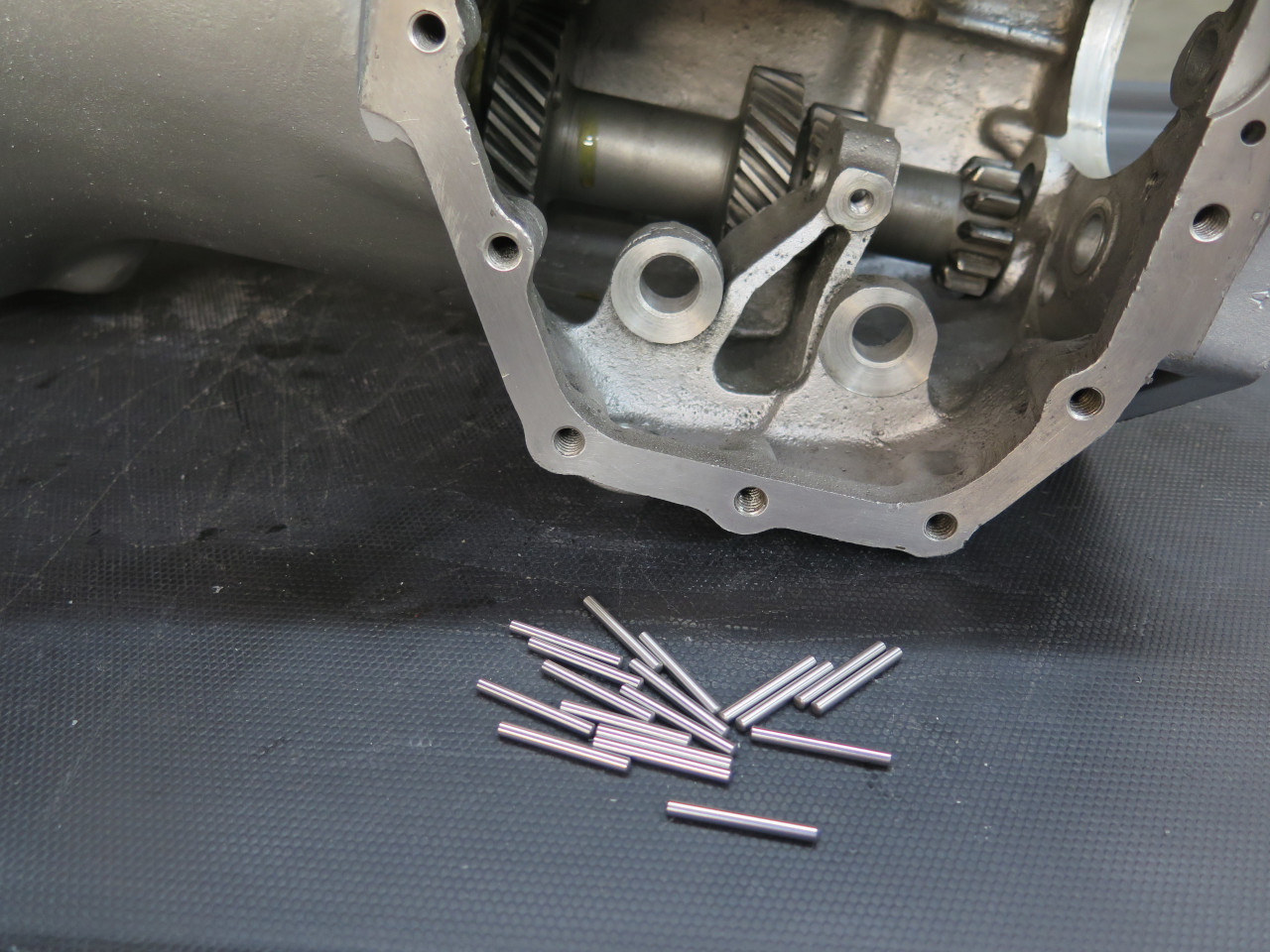
Rebuilding the laygear assembly is a bit of a project. There are
three internal needle bearings, each one composed of 20 loose
needles. End races and snap rings keep them sort of in place, but a
good jar will displace them. Grease helps.
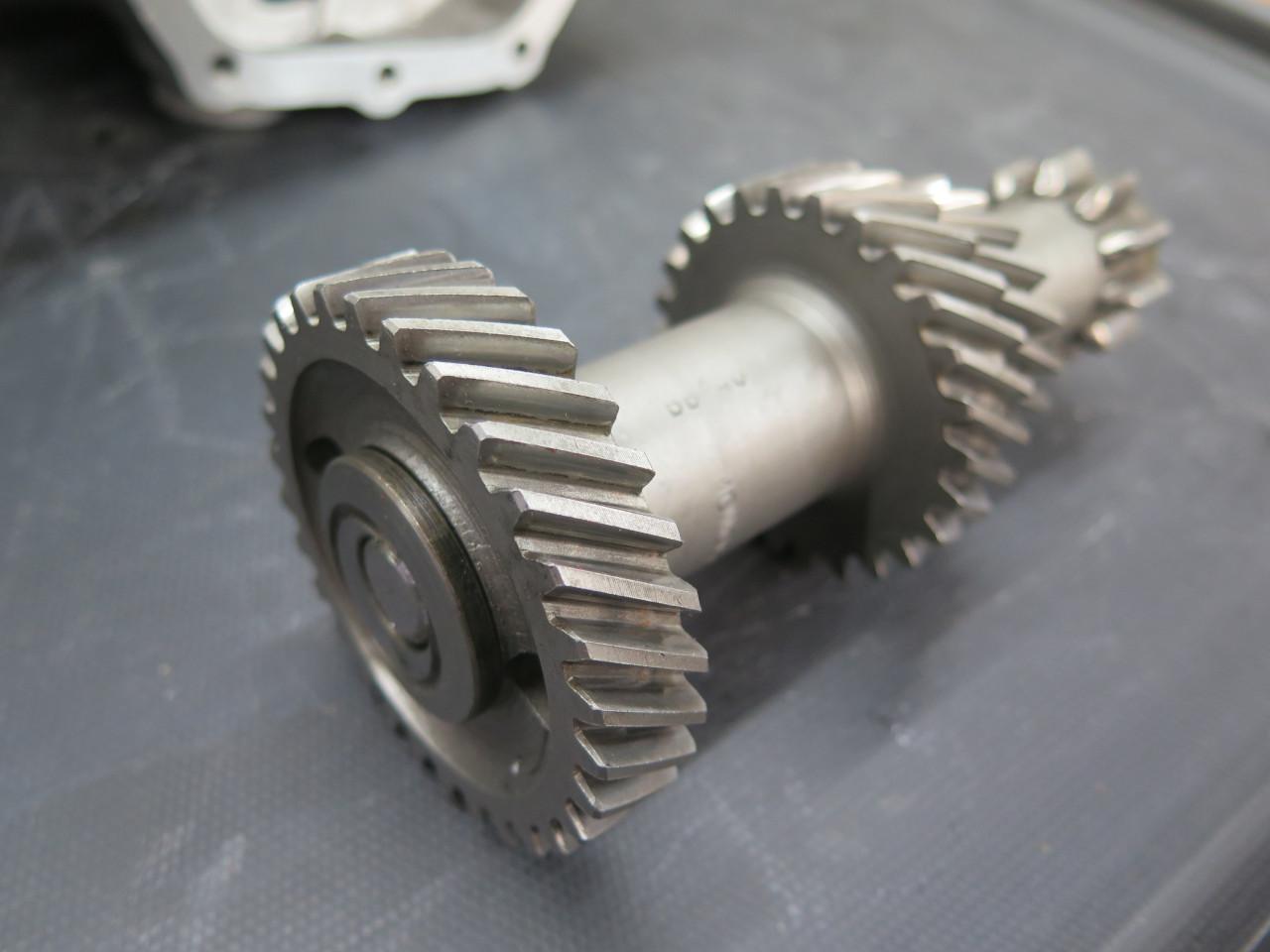
Moving on to the main shaft, I was frankly a little intimidated by the
number of parts there. Given the number of permutations for
assembling these parts, getting it right seemed unlikely. There is
apparently only really one thing to measure, and that is the 3rd
gear end float, so I measured that before taking anything apart.
The float was very large--more than 0.020", which is five times the
permissible value. So I knew there were some problems.
When I got up the nerve to start taking the mainshaft apart, I tried to
keep everything in order and in correct orientation. I was
especially interested in things that could explain the large 3rd gear
clearance.
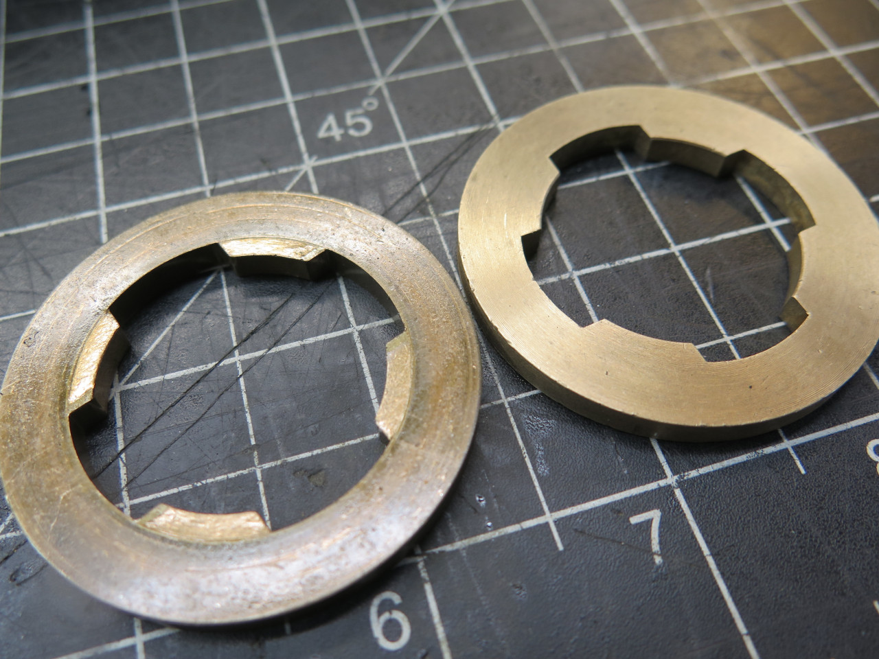
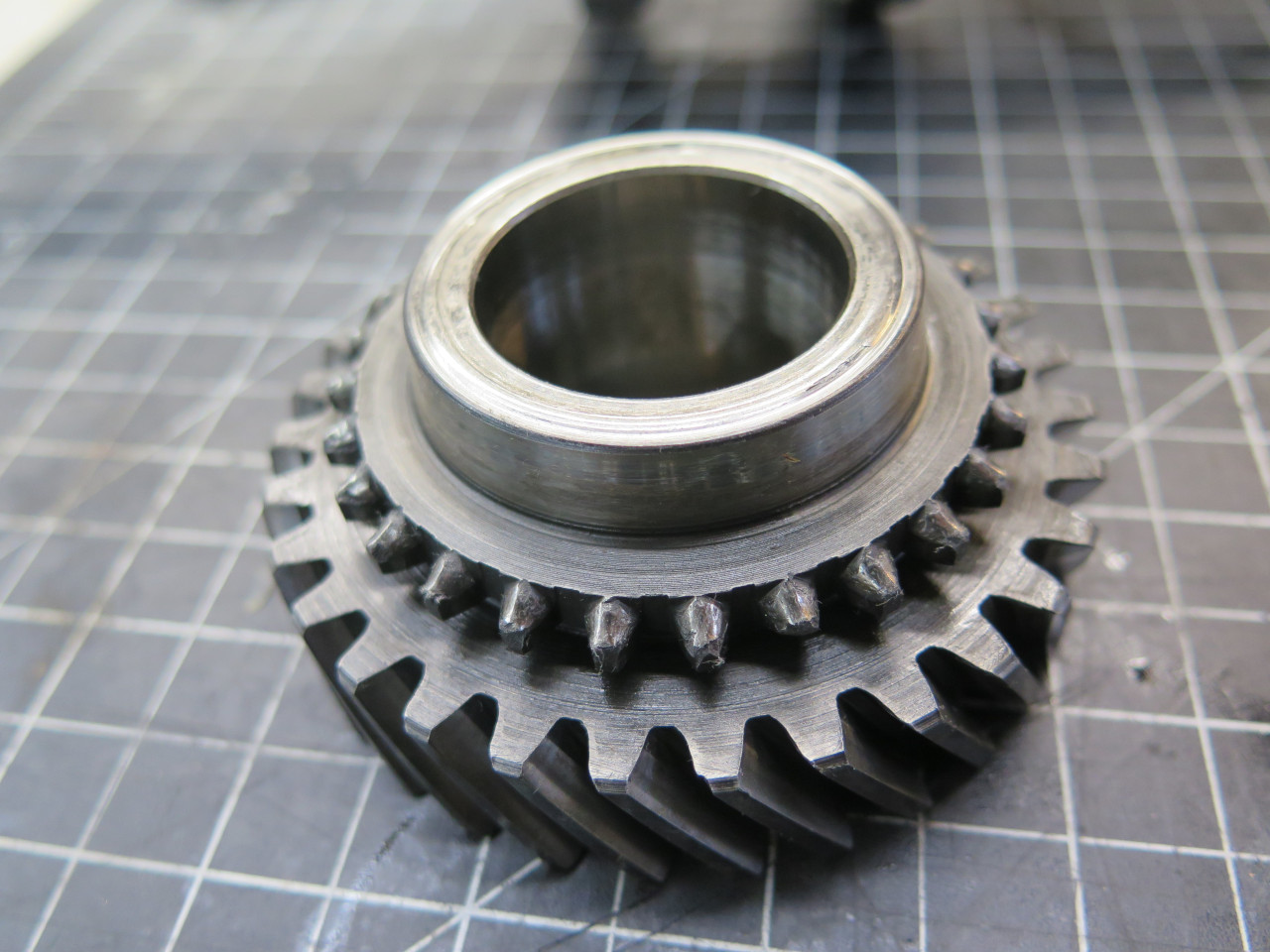
The 3rd gear runs on a bronze bushing between a bronze thrust ring at
the rear and a steel thrust washer at the front. The front washer
is captured in a groove in the shaft. The rear ring is captured
between the second and third gear bushings. The bronze ring showed
some signs of wear, so I ordered a new one. I also found that the
front thrust washer is available one size thicker than the one I had,
so I ordered that, too.
With these new parts, the 3rd gear clearance became about 0.005"--still slightly out of spec, but I'm going to live with it.
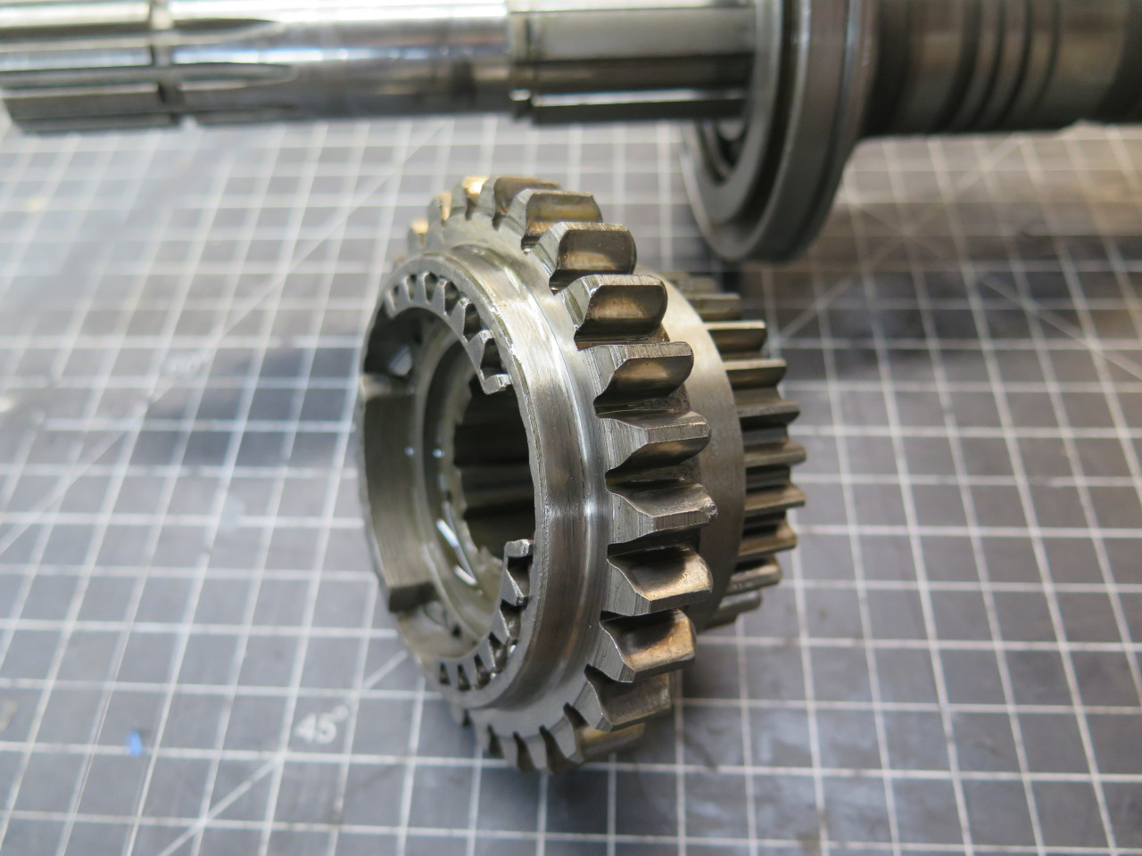
In these gearboxes, shifting is accomplished by sliding a sleeve over a
hub such that the sleeve locks onto an adjacent gear. The hub is
splined to the shaft, so this can effectively lock the gear to the
shaft.
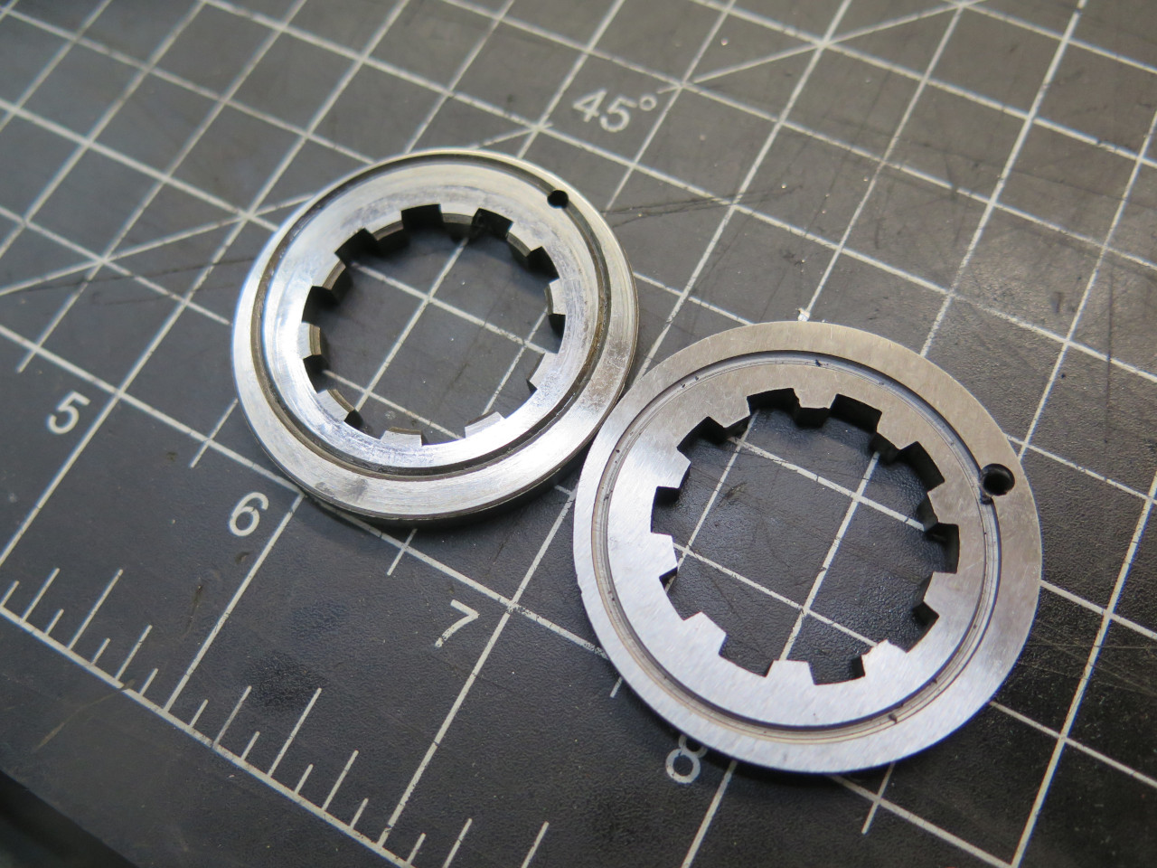
There are two hubs--one for first and second gear, and the other for
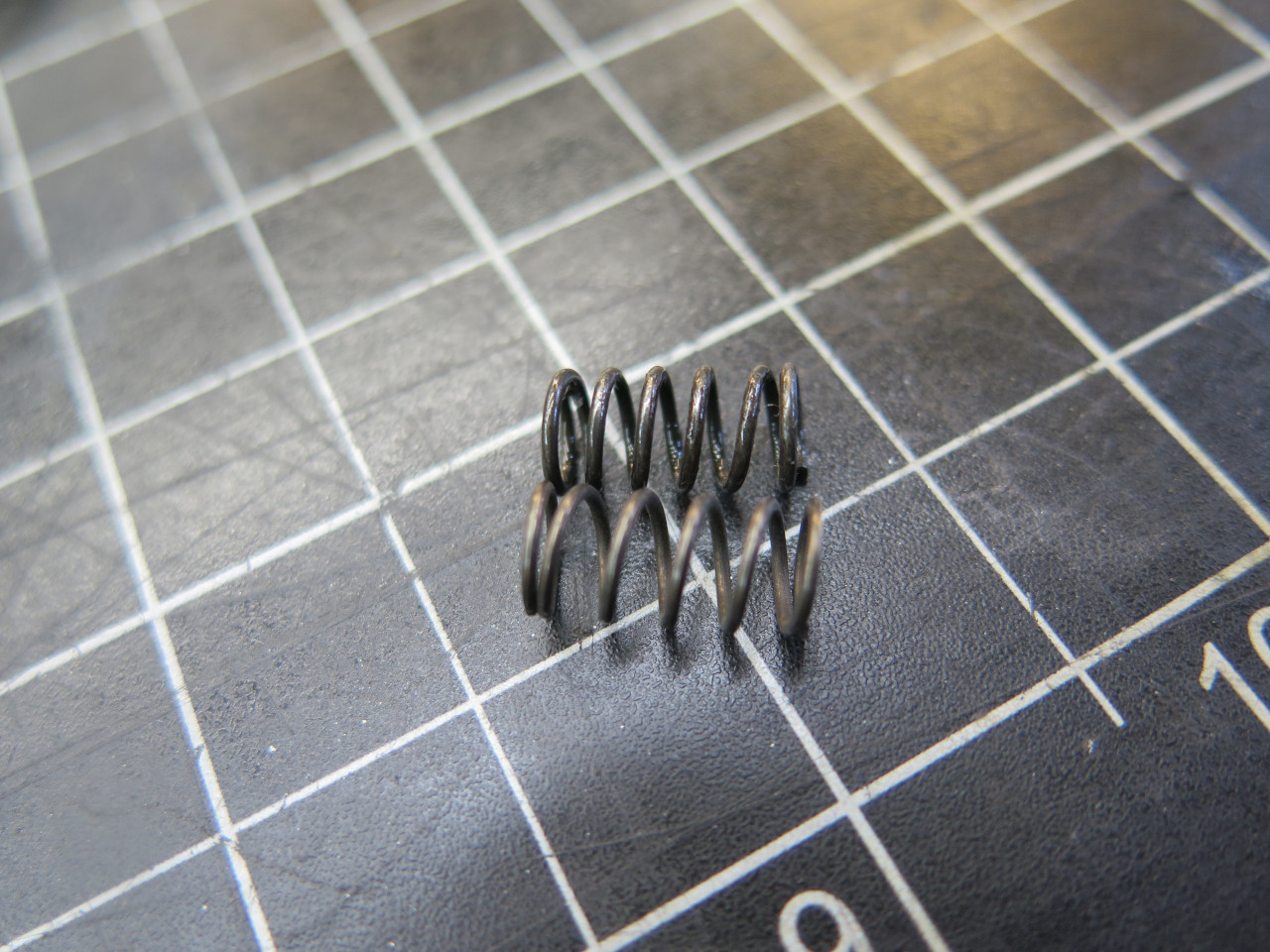
third and fourth. The hubs have spring loaded detent in their
central position to keep the hub in neutral when not activated, and this
contributes to the force needed on the shift lever to change
gears. Low detent resistance can make the shifter feel sloppy.
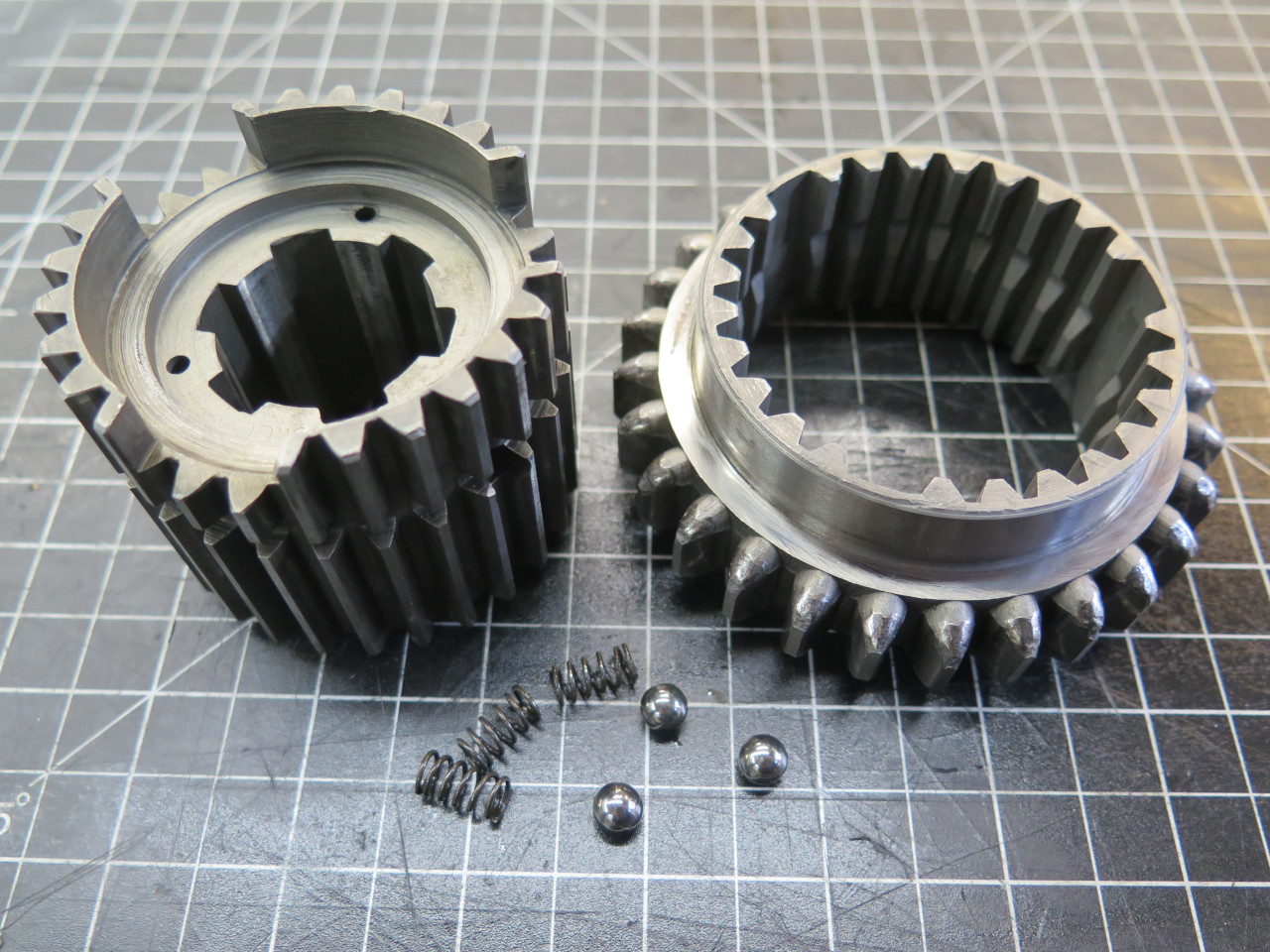
I had ordered new springs for these detents, and I was curious if they
made any difference. The original springs appeared to have relaxed
over the decades.
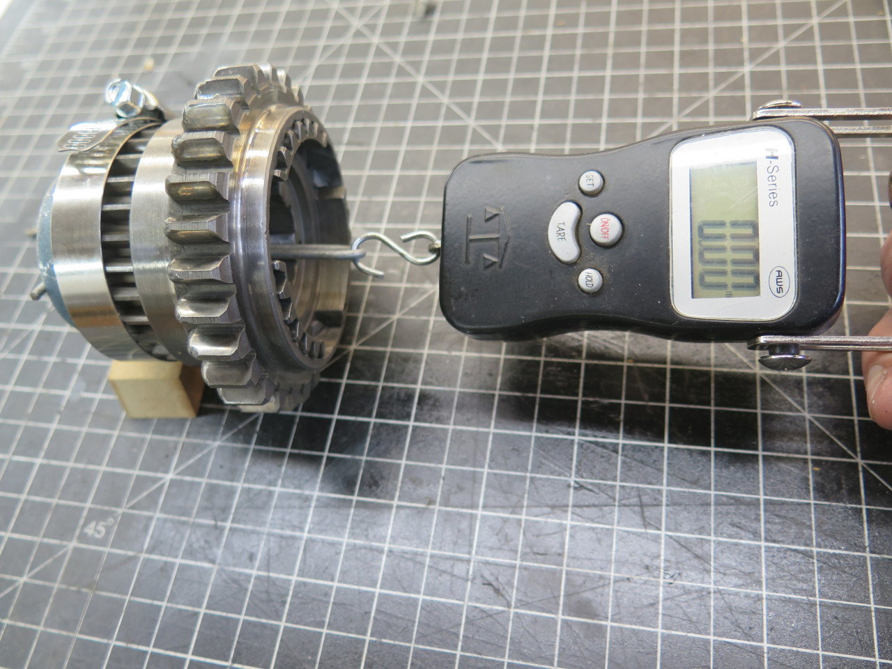
The setup was simple. I held the sleeve stationary, and measured how much force it took to pull the hub out of the detent.
With the old springs, it was about 6.5 pounds. With the new ones
it took just over 9 pounds. The other hub showed a similar
result. I consider changing the springs worthwhile.
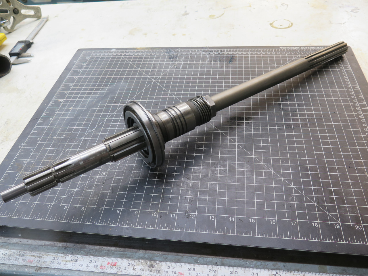
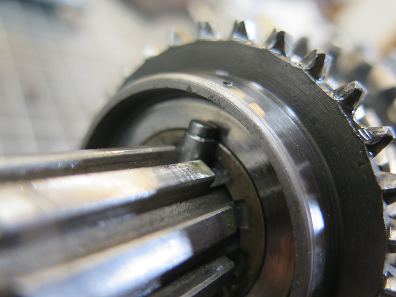
On to assembly. First, some items have to be slid on from the
rear, including the new bearing with its housing, the screw oil pump,
and the speedometer drive gear.
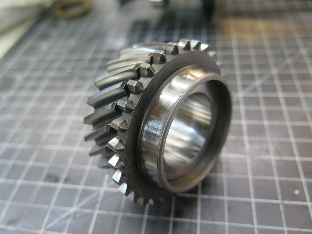
Then, from the front end, the 1st/2nd hub along with the new 2nd gear
synch ring. Then a thrust washer and 2nd gear, which rides on a
bronze bush.
Then the new bronze ring mentioned earlier, followed by 3rd gear and its bronze bushing.
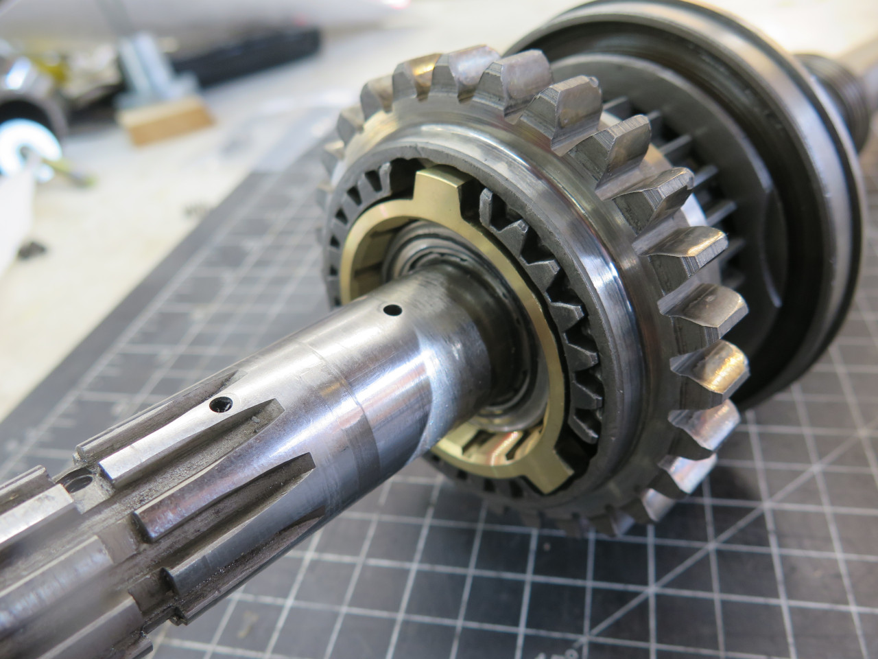
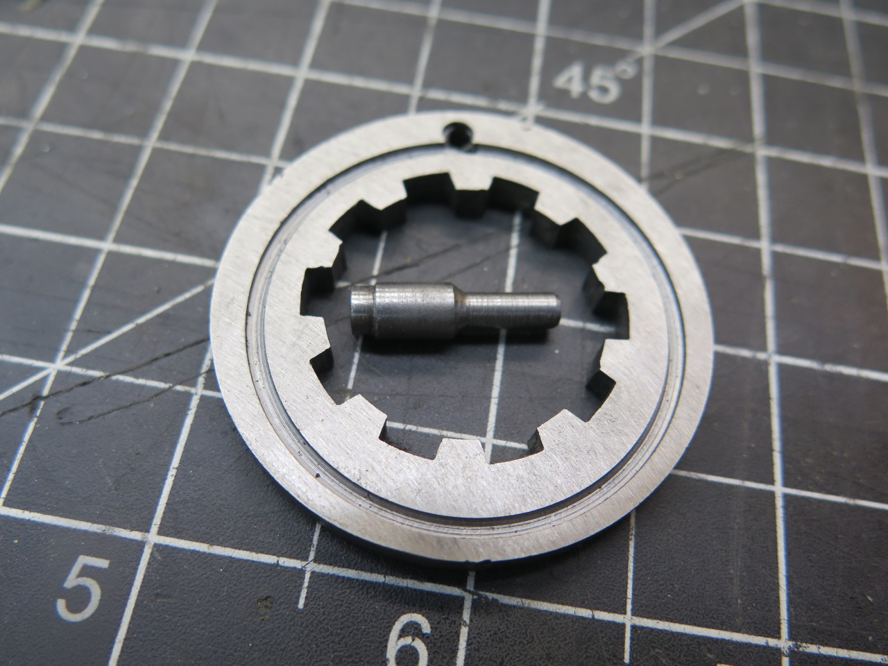
Then, to capture everything so far onto the shaft, the other thrust
washer, but this one is rotated into a slot on the shaft, and locked in
place with this spring loaded "peg". Then the 3rd/4th hub is slid
on with its new synch rings.
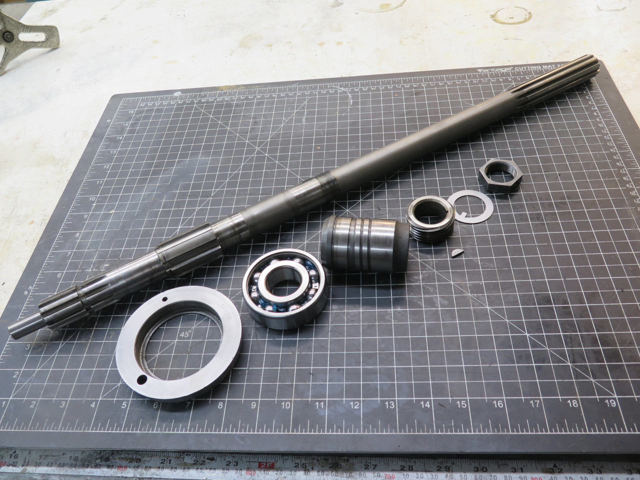
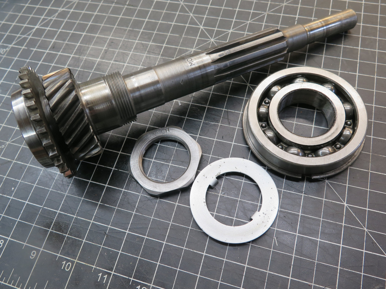
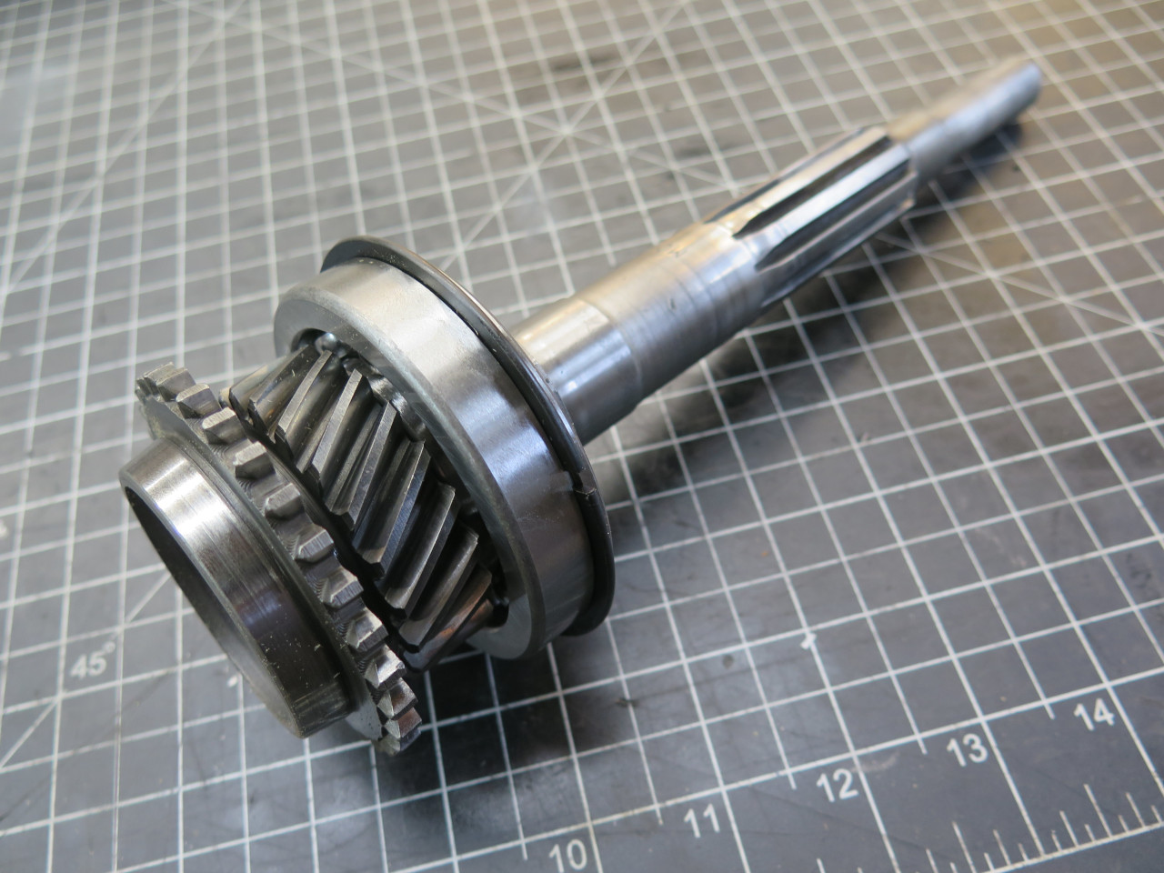
The input shaft is simple by comparison-- just the new bearing and its retaining nut and washer.
The case got a nice coat of tasteful "cast aluminum" paint, and we're ready for reassembly.
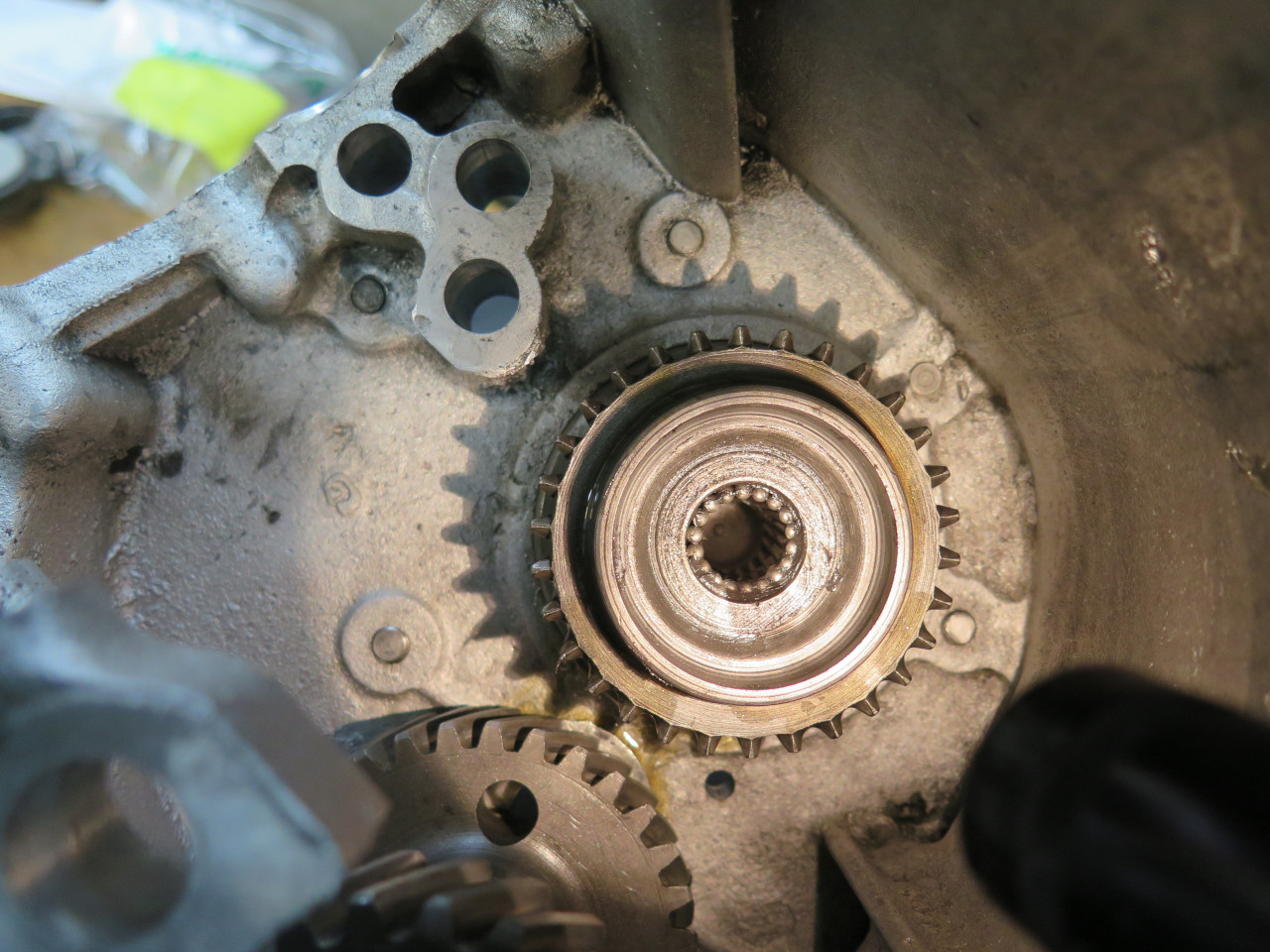
The layshaft assembly has to go in first, but it has to sit in the
bottom of the case. A dummy short shaft goes in to keep the
bearings in place.
Then the input shaft goes in from the front. The bore on the end
of the input shaft gets a bearing compose of loose rollers which
receives the nose of the mainshaft.
Then the mainshaft from the rear. It plugs into the end of the input shaft.
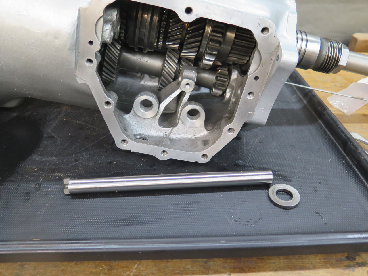
The layshaft assembly is then somehow raised up so the real layshaft can
be pushed in, displacing the temporary shaft. The small thrust
washer, which had fallen out by then, had to be re-inserted.
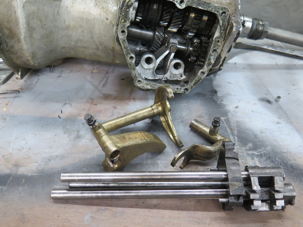
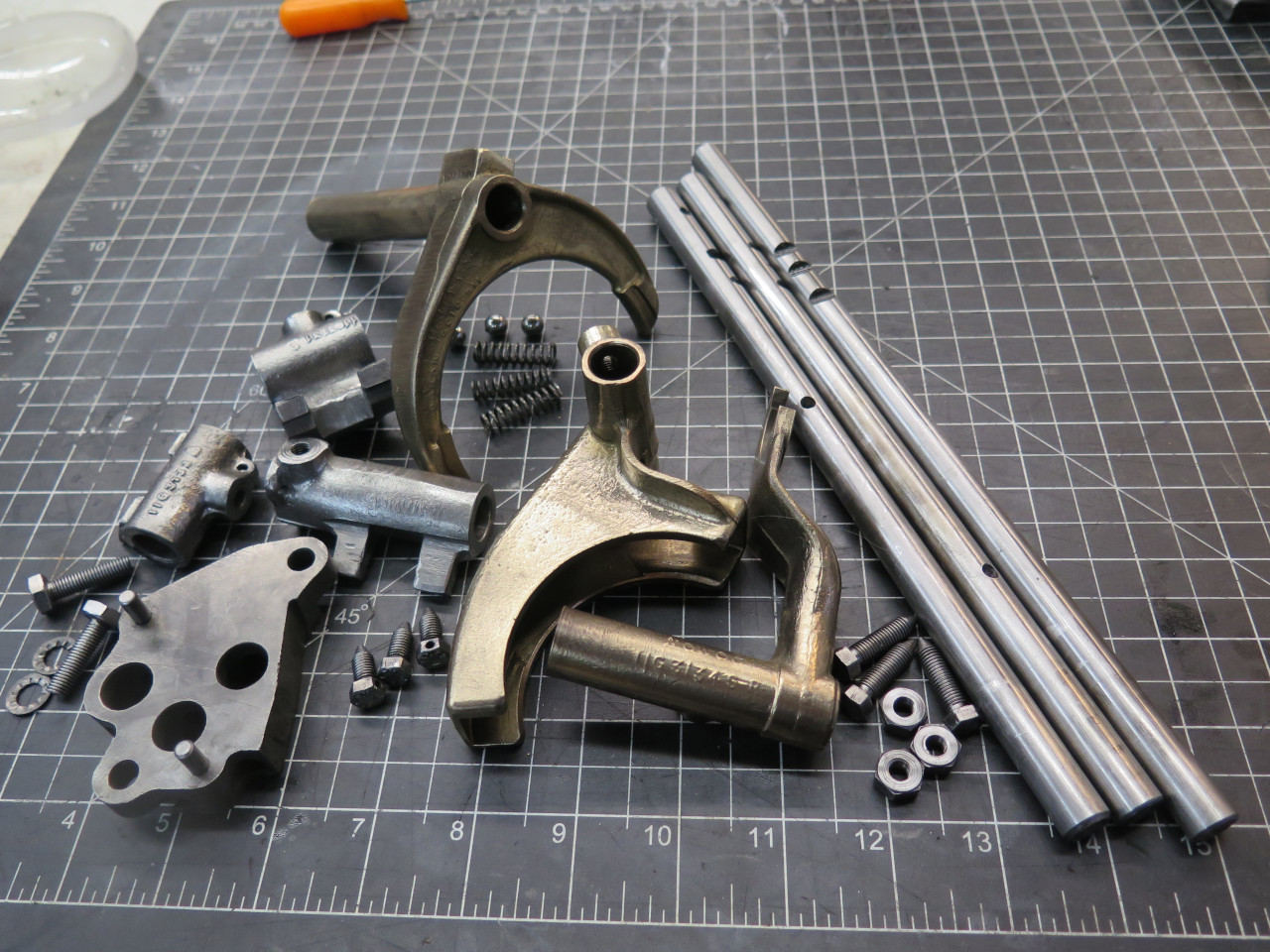
Now, on to the shifter paraphernalia.
I first assembled the three fork rods into the detent block. The
block holds a spring loaded detent ball for each rod. The chances
of having a ball launch to somewhere out of sight is very high here.
The three rods were then inserted into the case, and the appropriate
fork was slid onto each rod and mated with its hub. As far as I
know, they will only go together one way. But wait! The
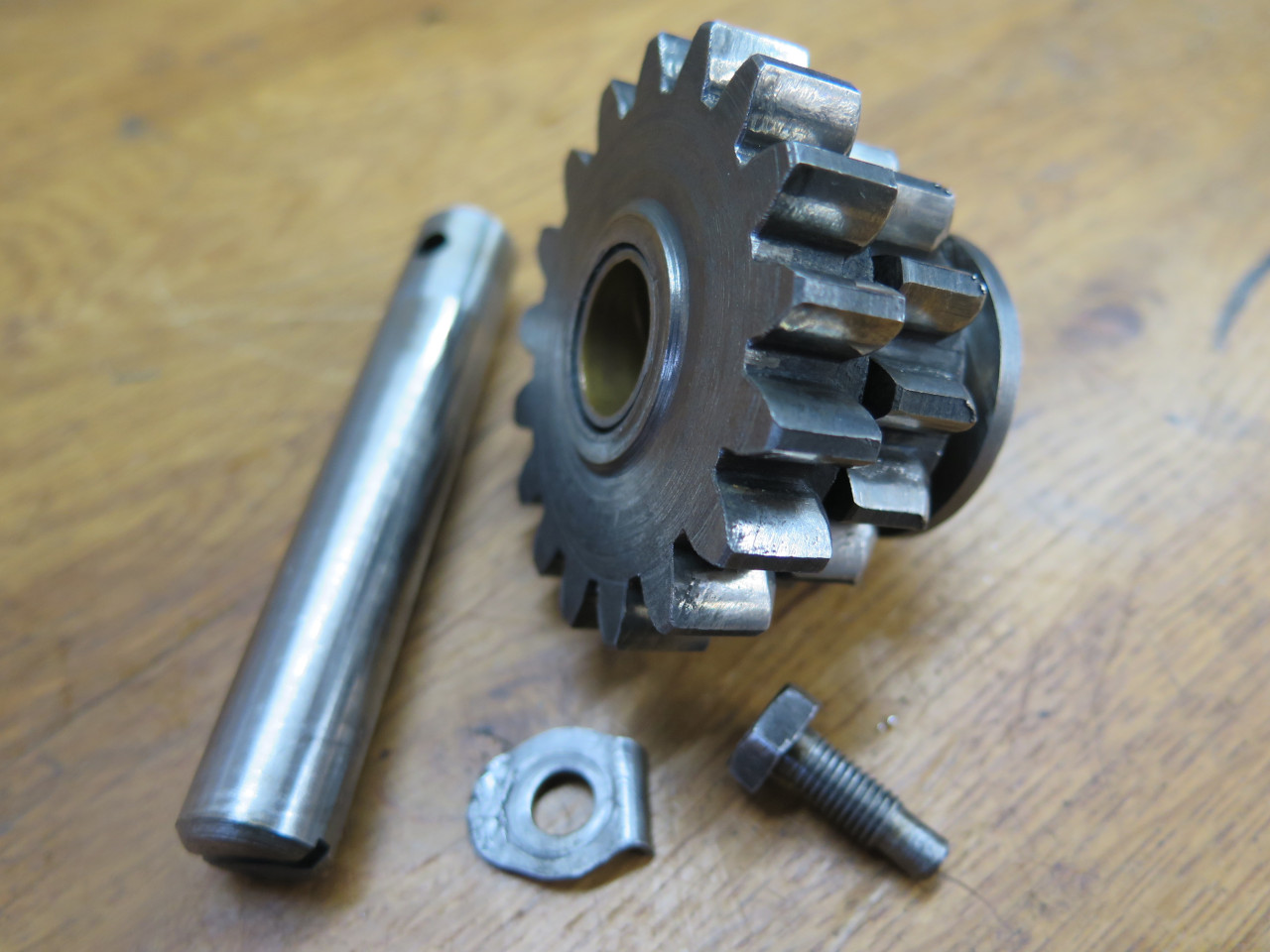
reverse gear has to go in first. The gear and its shaft were in
very good shape and need no attention.
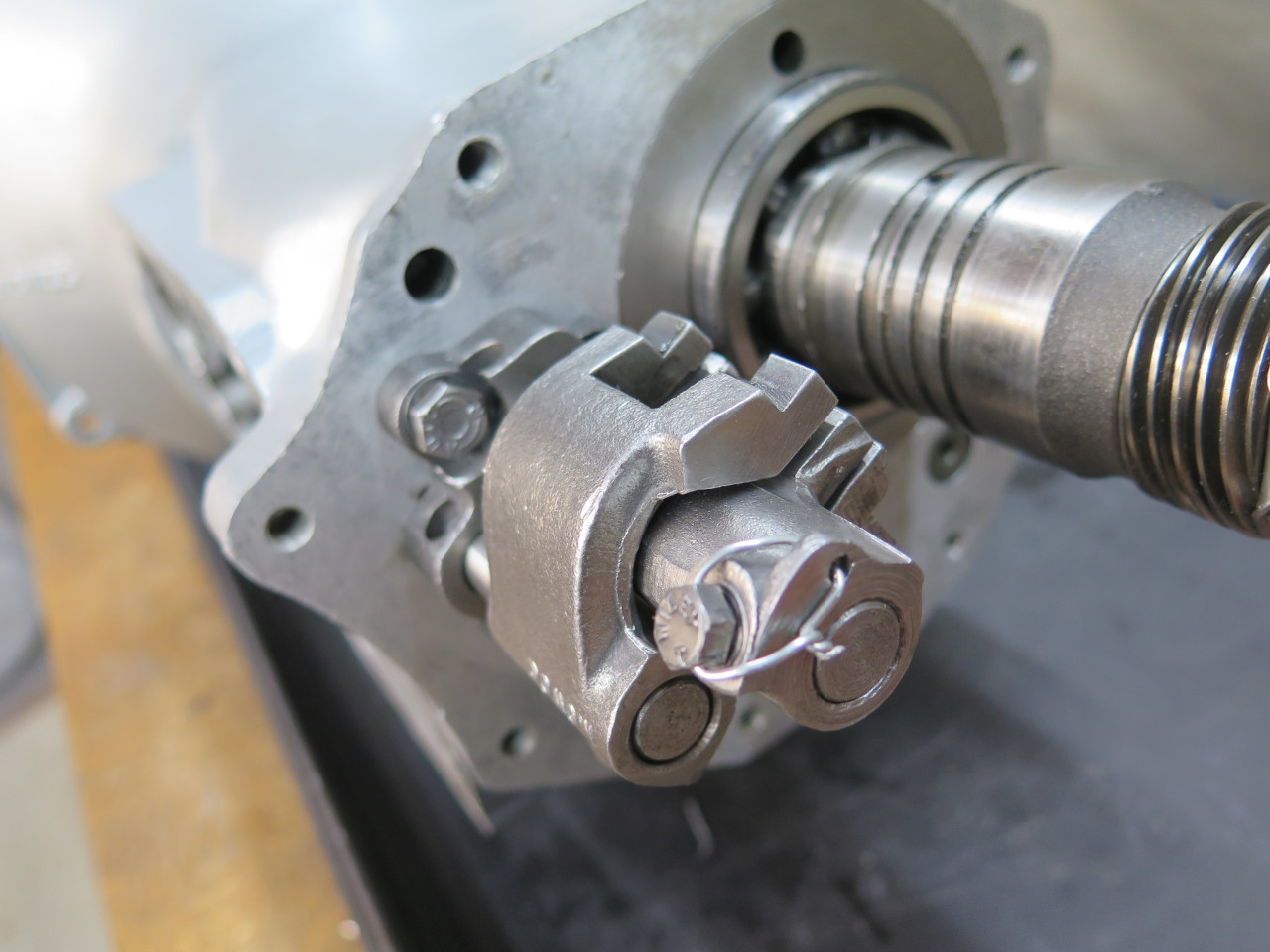
The rods then got their respective selector ends installed. They had safety wire originally, so I put in safety wire.
The access cover got a lovely powder coat and the fasteners nice new
zinc. But I'll leave the cover off until after some testing.
Front Cover
The gear case has a cover inside the bell housing. It carries the
oil seal for the input shaft and has a pair of abutments to hold the
shaft for the release bearing fork. It also captures and locates
the input shaft bearing. For this, it needs to have minimal
clearance to the bearing outer race. This is accomplished with
shims.
Since I had changed the bearing, I thought it important to check the
clearance. I used Plastigage for this, putting a little piece on
the cover and bolting it down, with the gasket and the two original
shims in place. The two original shims measured 0.011" together.
The clearance was about 0.007". I'm not sure I've seen an actual
spec on this, but imagine that something around 0.002"-0.003" would be
about right. I'm not sure if these shims are available, but I had some
0.005" stainless shim stock around. So here is my front cover with
two original and one home made shims.
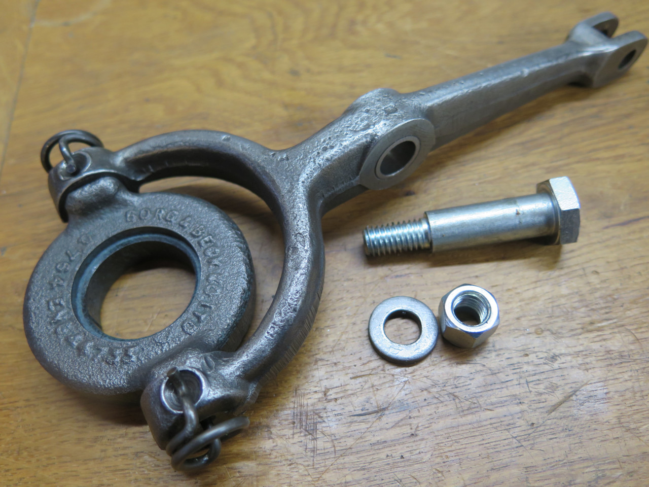
This paved the way for the clutch actuating parts. These were the originals.
The original pivot bolt had some wear, and seemed pretty loose in the
fork. I bought a standard shoulder bolt of the right size, and
replaced the bushing in the fork, too.
I bought a new release bearing as a matter of course, but it was obviously different from the original.
The difference in height seemed like it could make a difference, and
inquiries on some MGA forums didn't give a definitive answer. In
the end, I decided to use the original bearing. It was a quality
Borg & Beck part, bought during my engine work in the 70s, and
didn't have many miles on it.
Ready for install...
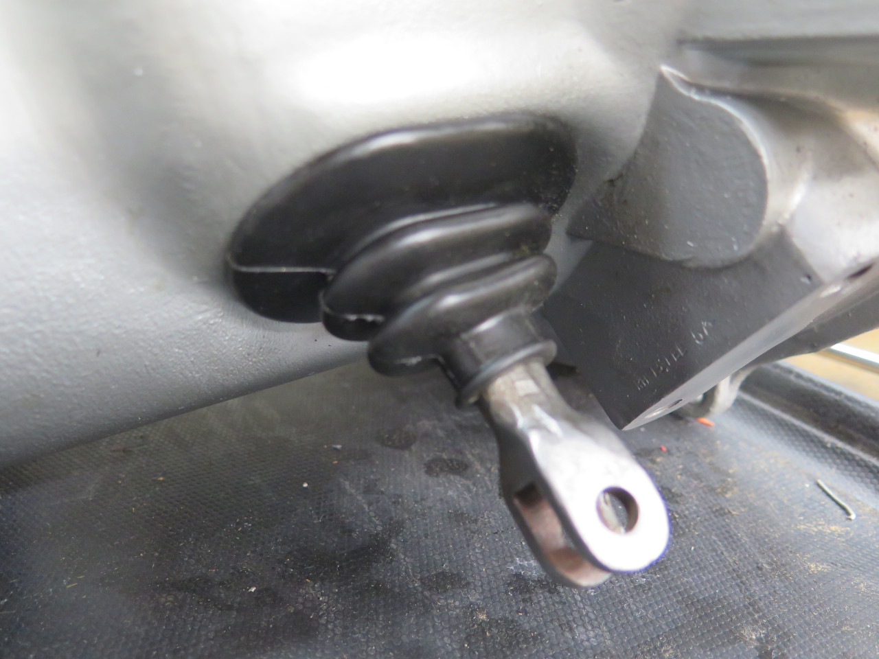
I also bought a new rubber boot for the clutch arm. But honestly,
the original (70s replacement, actually) felt and looked better that the
new one, so I used it.
Final Assembly
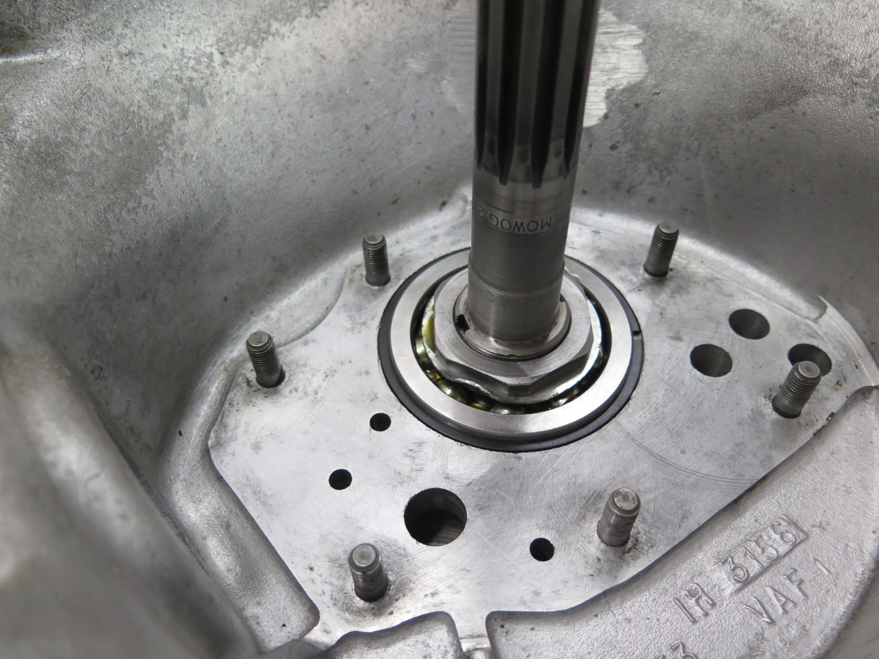
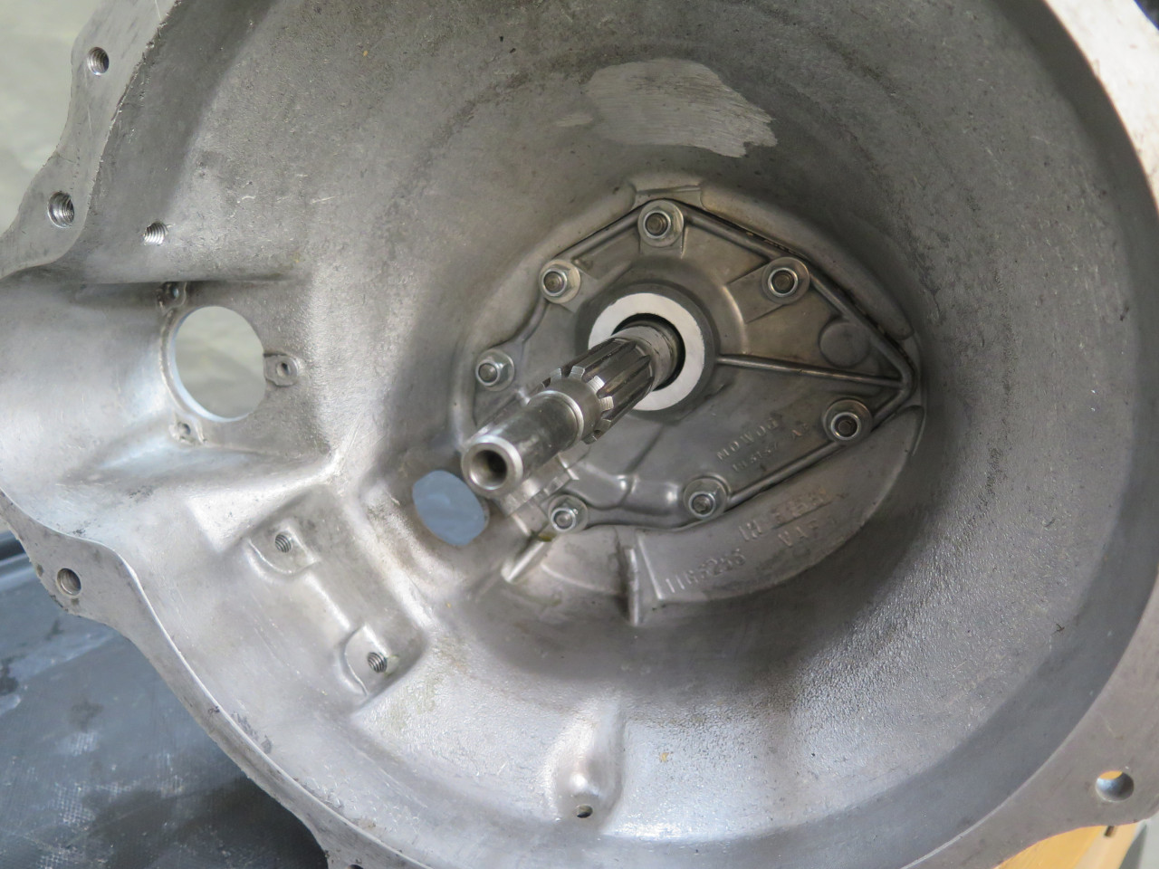
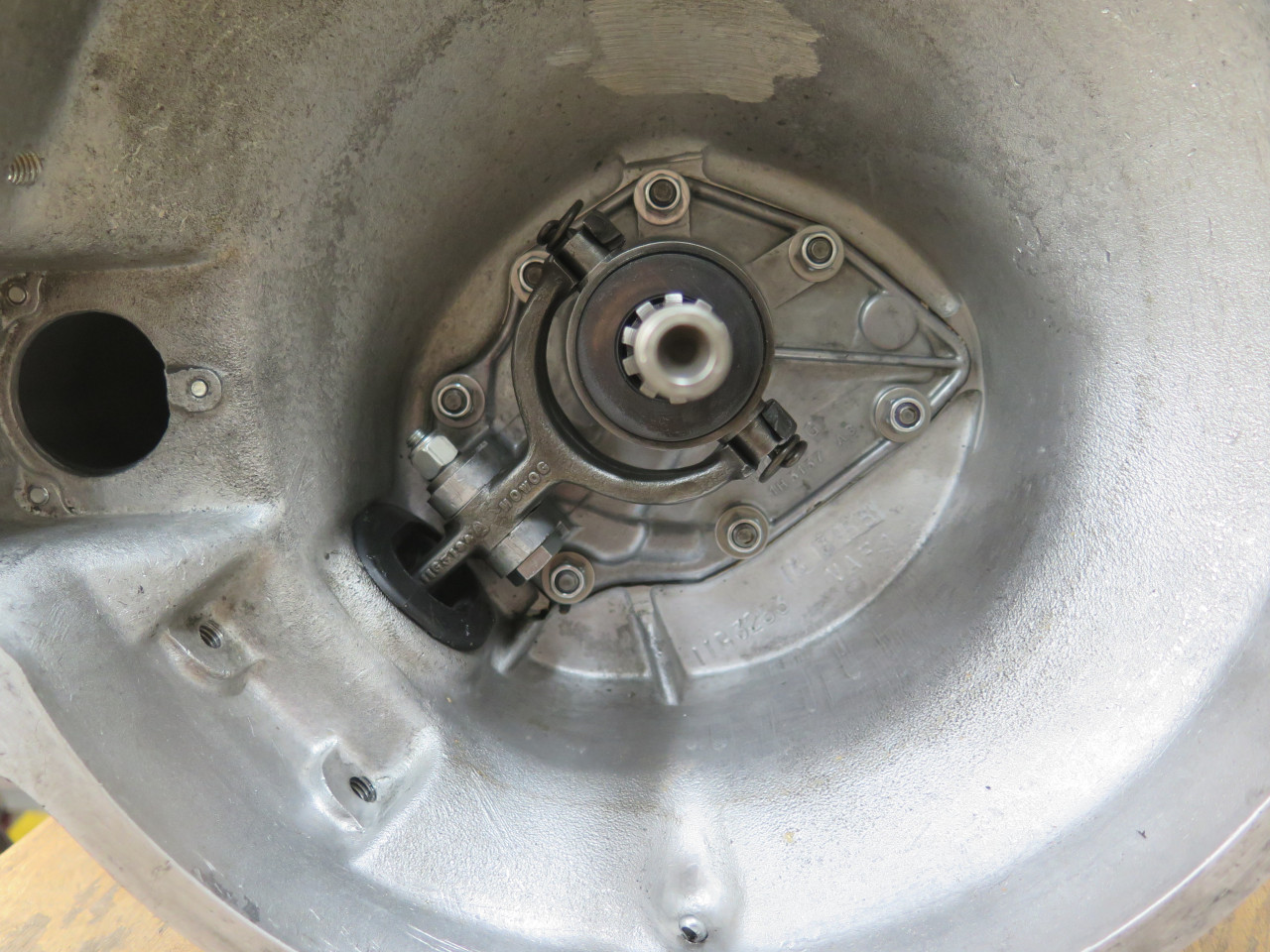
It seemed easier to mount the rear extension by turning the gear case up on the bell housing end.
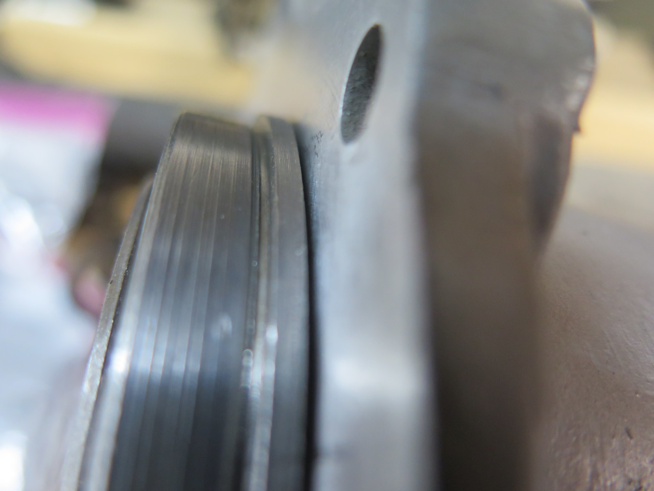
When I lowered the extension, I couldn't seem to get it to seat
fully. There is a pin that has to go into both the rear extension
and the rear bearing housing that can be difficult to align, but it
seemed to be going into both holes. The extension lacked almost 1/16
inch from seating fully. In desperation, I removed the rear
bearing housing and tried it on the extension. it would not seat.
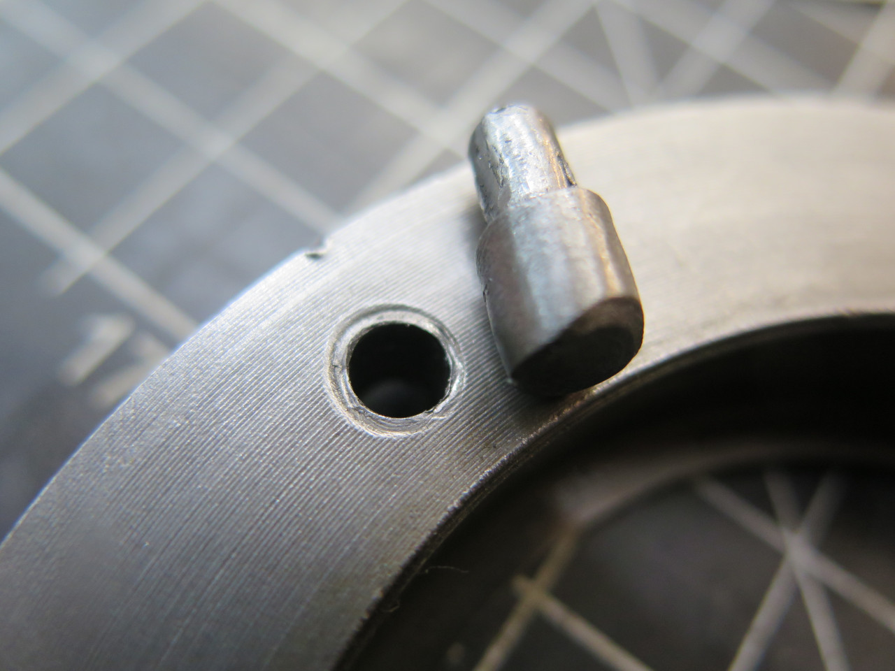
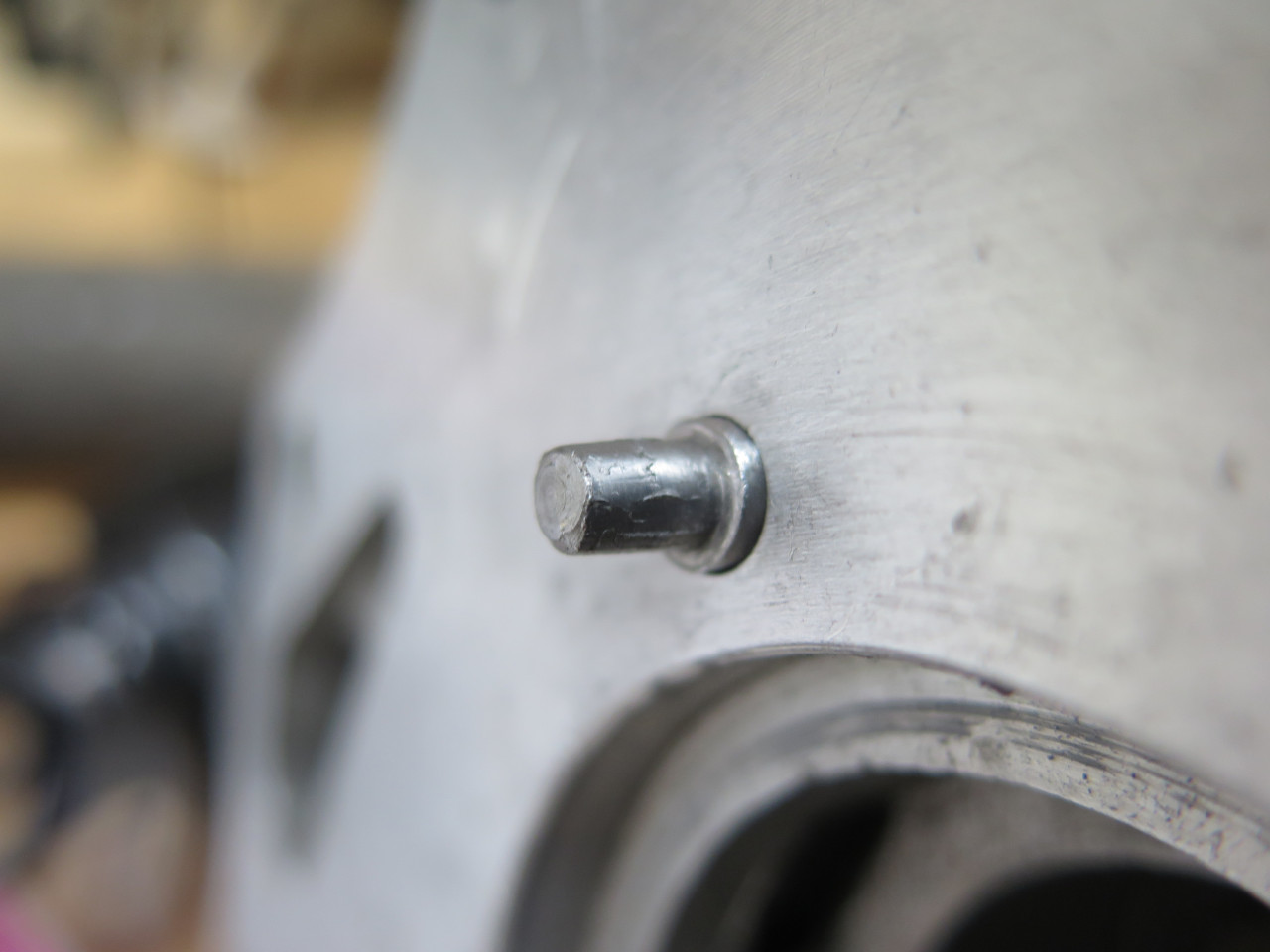
I traced the problem to the alignment pin. It's a stepped pin with
the large end in the extension, and the small end in the bearing
housing.
That sort of mashed area around the hole in the housing was my
clue. Putting the large end into the extension as far as it would
go, the step was proud of the surface. I believe it left the
factory that way.
Grinding away some of the big end of the pin fixed the problem. The extension then went home properly.
There is an "arm assembly" that then needs to go into the extension opening. I believe it helps guide the gear selection.
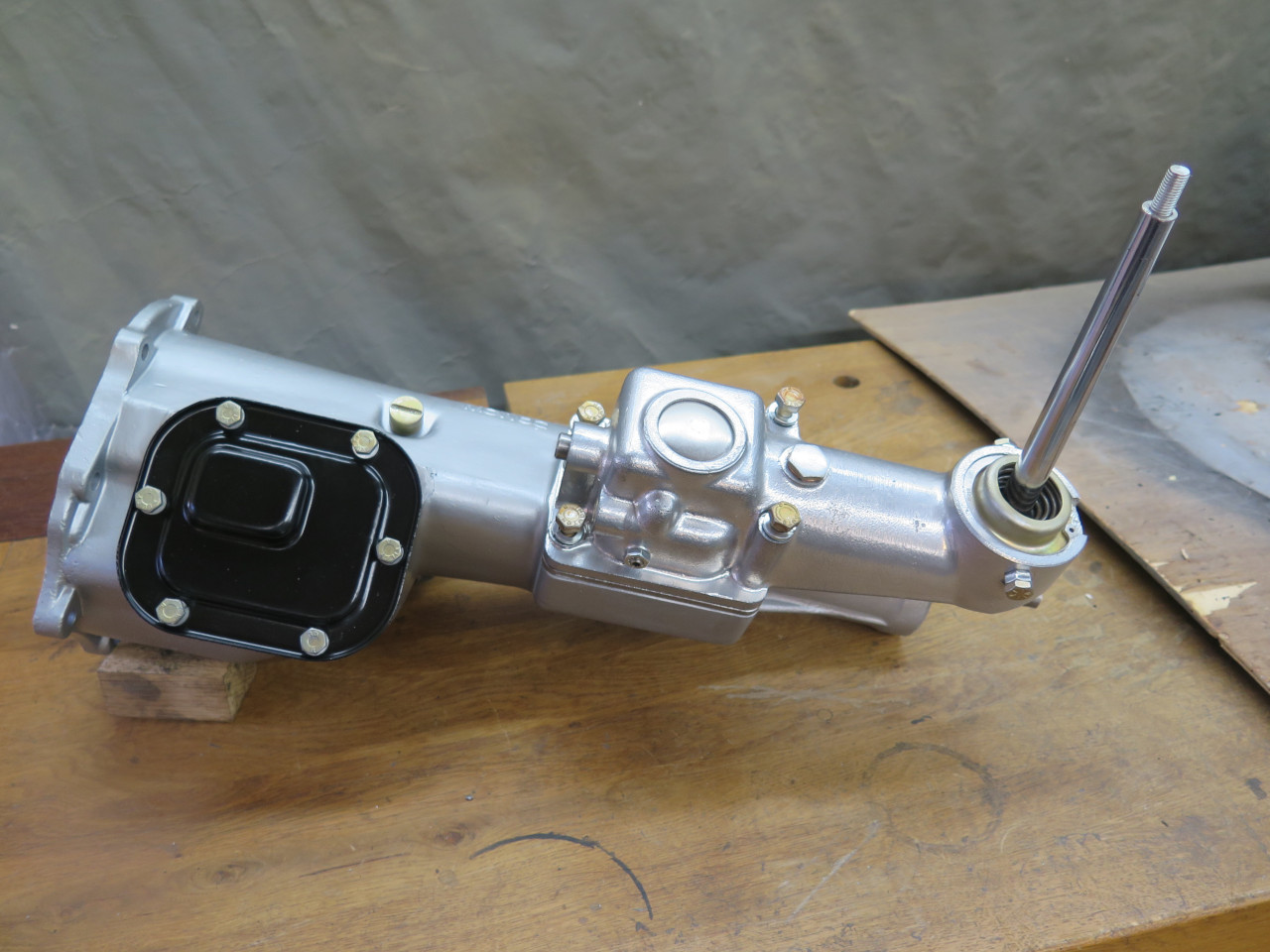
Covers put on dry for photo-op. They will come off again for final testing.
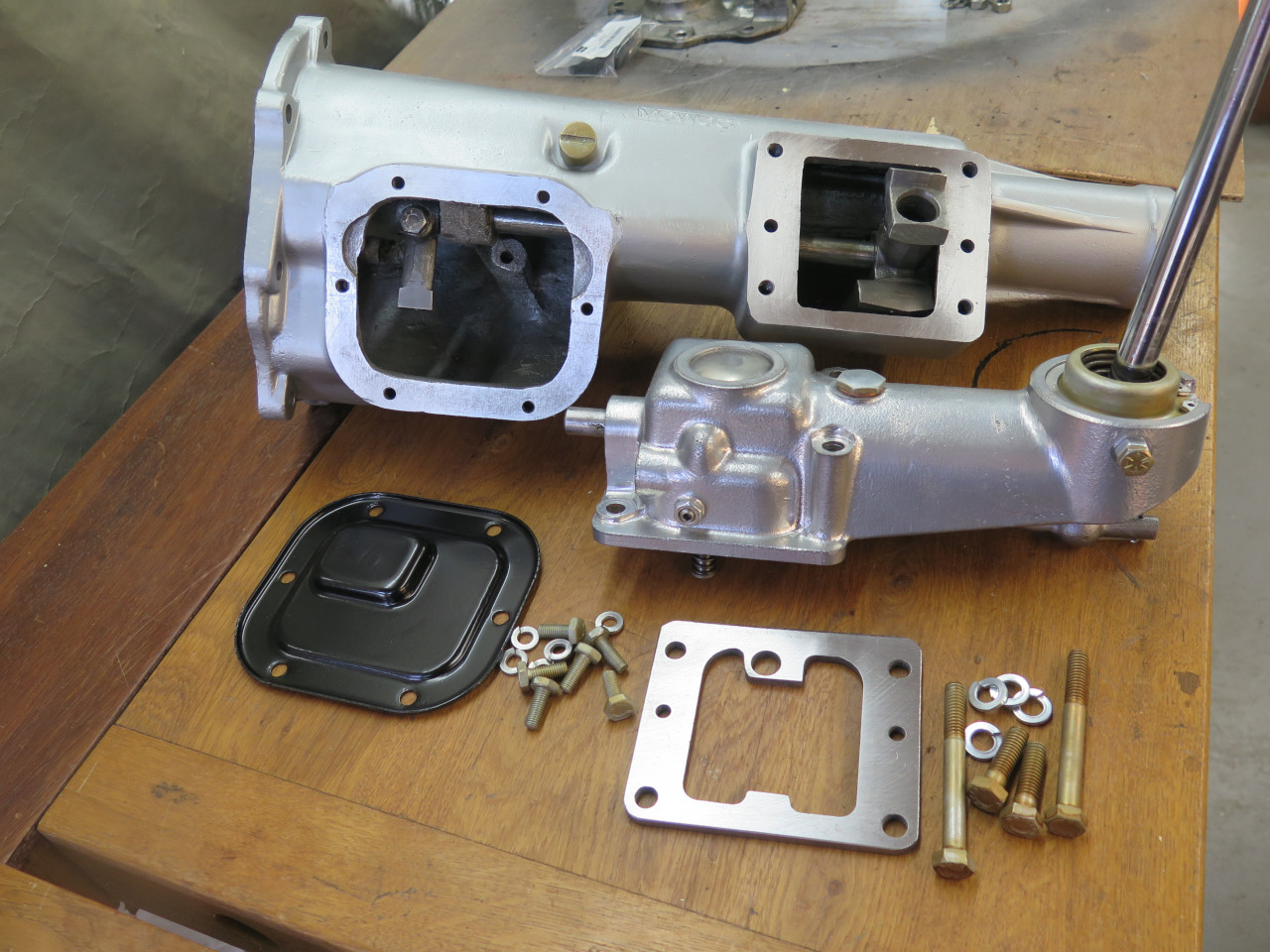
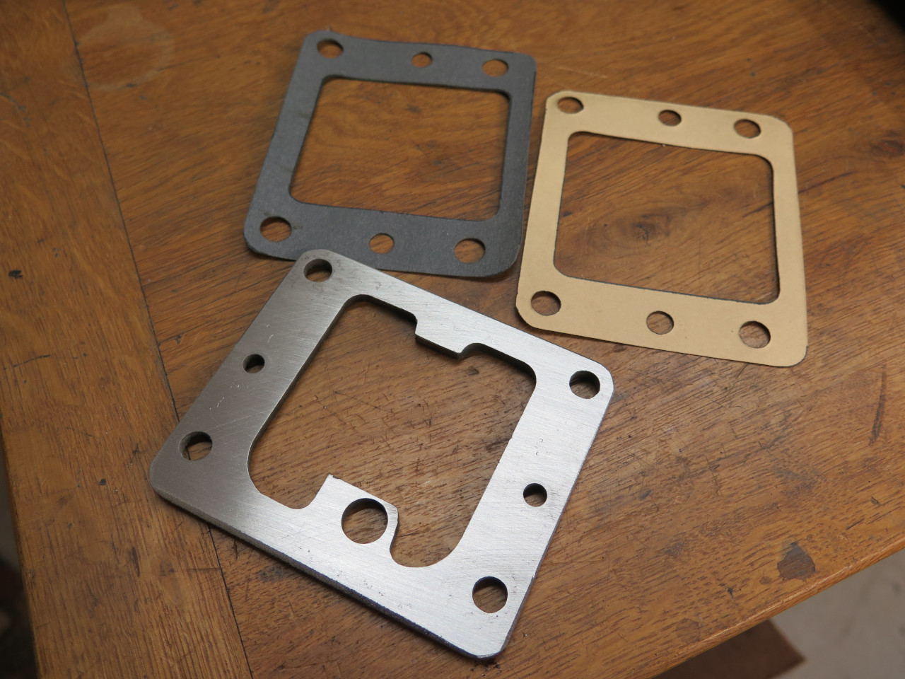
This plate goes between the remote control tower and the rear
extension. It limits the sideways travel of the shift lever.
It takes a gasket above and below, but my gearbox gasket set only came
with one. The dark one is home made.
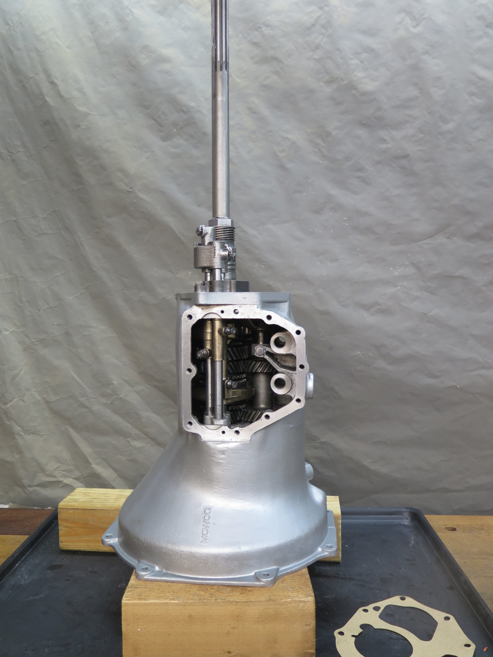
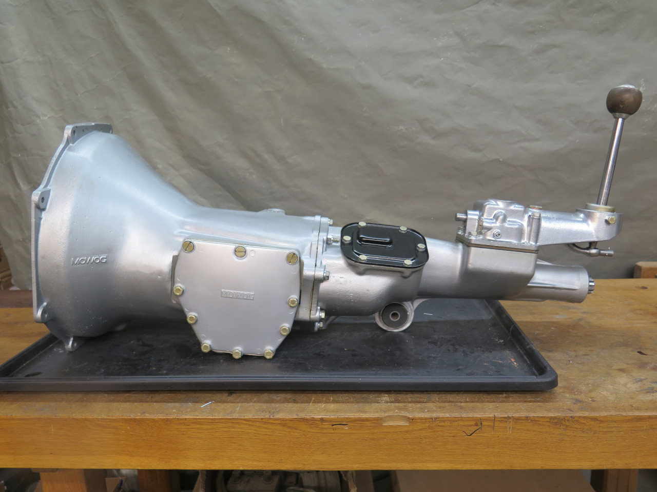
The whole enchilada--
Miscellaneous
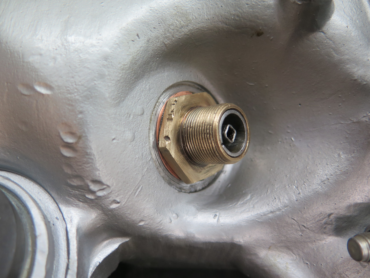
Just a few odds and ends left. A nice drain plug for one.
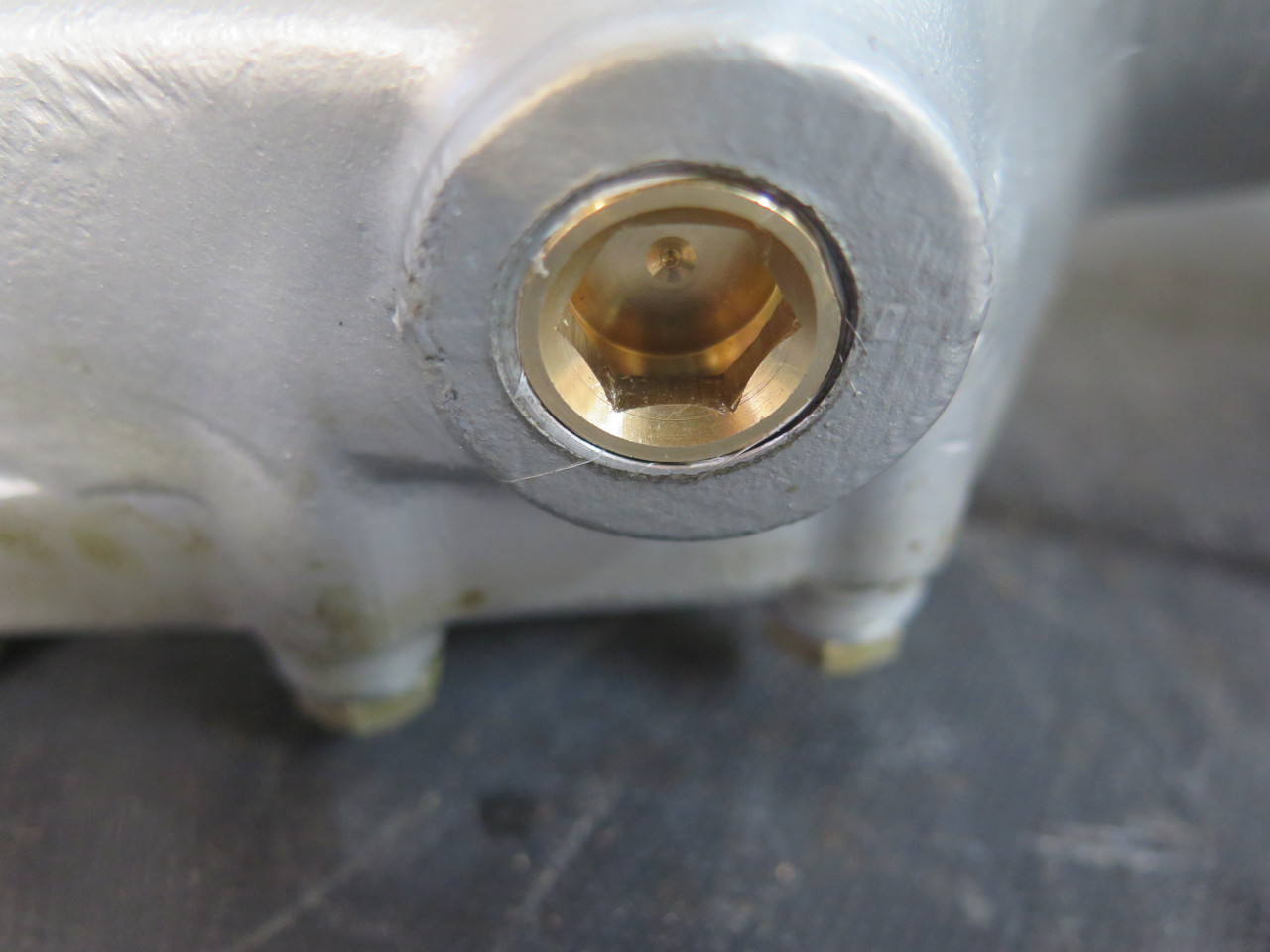
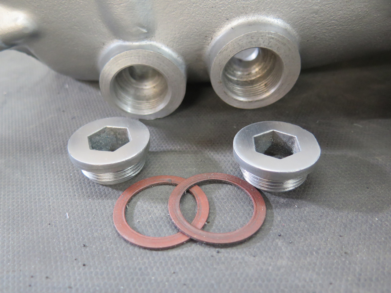
There were a couple of threaded ports down low on the right side of the
gear case. These had threaded plugs in them. I don't believe
there is any functional reason for these. They were likely for
fixturing during manufacture.
Since these ports are below the oil line, they need to be sealed well. I used a thread sealant.
And the dip stick.
Then there was the starter drive cover. This is what I found on the gearbox. It's something I made in the 70s.
There probably aren't many MGAs today that even have this cover, and I'm
not sure that they all even had them from the factory, but they did
exist. Research turned up some pictures, and I 3D printed a
facsimile.
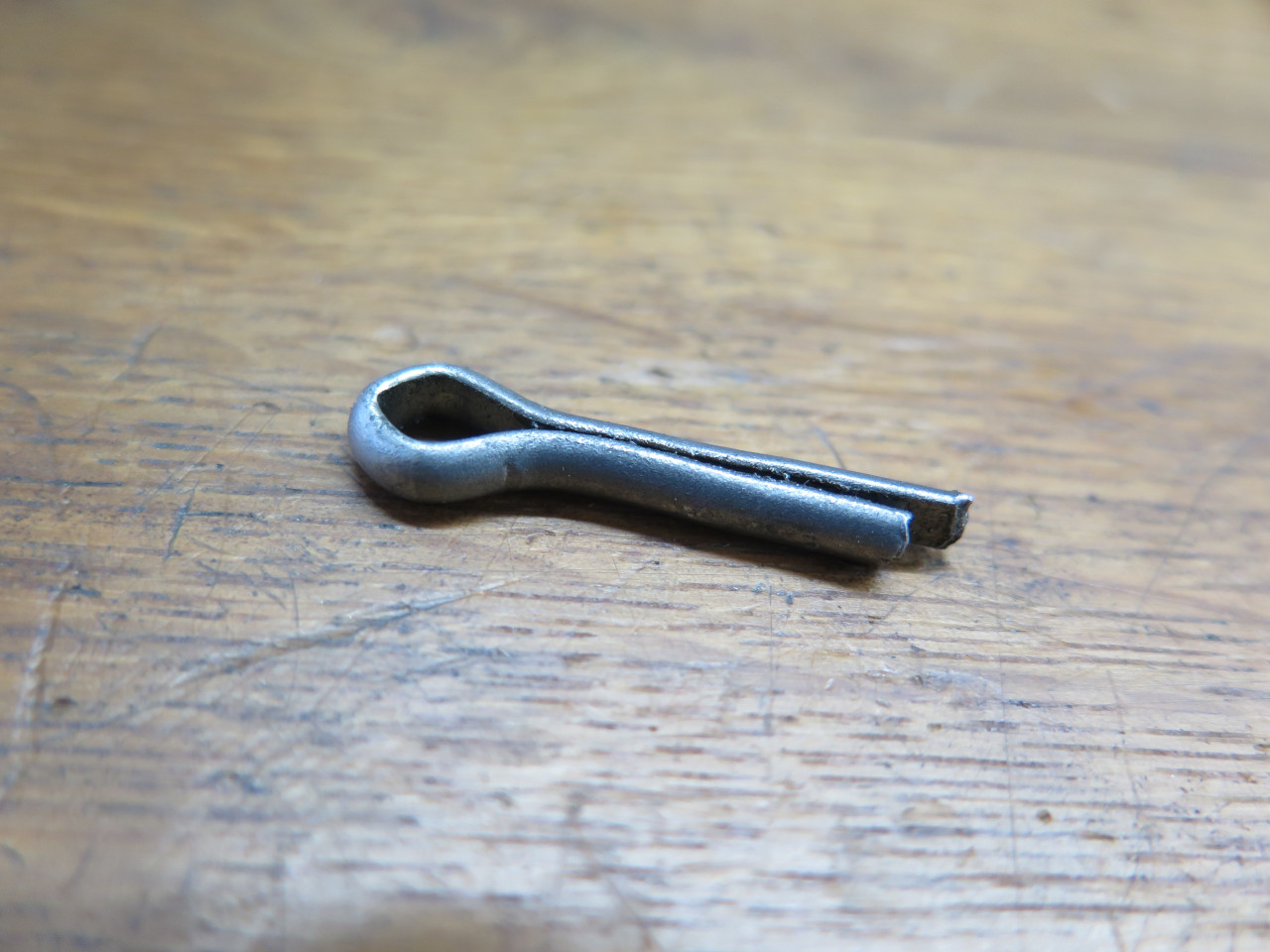
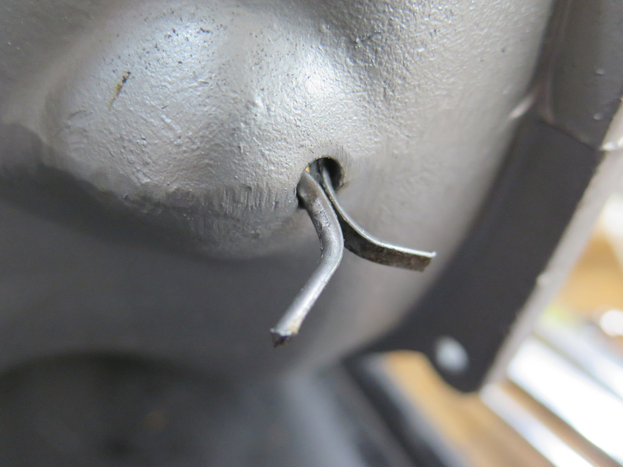
And, finally, the gearbox would not be complete without a final crucial
part. This is the cotter pin installed in the bell housing weep
hole to keep it open. I used the original because I'm so
sentimental.
Testing
There is only so much bench testing I could do, but I certainly wanted
to make sure I could select all four gears and reverse, and that the
relationship between input and output was what I expected.
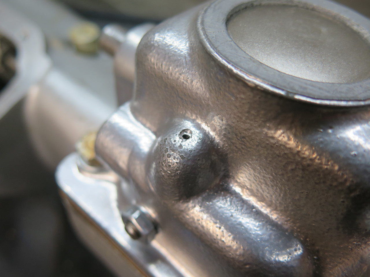
During the first test, all seemed well, except I couldn't get the lever
into reverse. I finally traced it to the detent ball in the
reverse plunger on the remote control tower. It had slipped out of
its proper place, and was lodged in the bore for the plunger, limiting
its travel. Removing that greased ball from the blind hole was
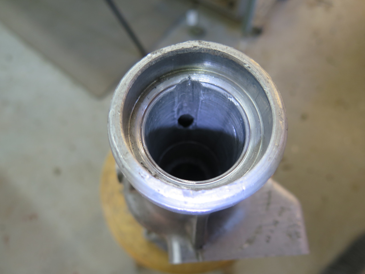
good for a couple of hours. I tried shock. I tried magnets. I
tried air. I tried vacuum. I finally drilled a small hole
in the casting into the top of the bore. I'll patch it with a dab
of epoxy.
A couple of short videos of the mechanisms working as designed.
The gearbox wasn't fastened down to the bench, so they are shaky in
places.
This project was a pretty major one. I've only done a couple of
gearboxes before, but still felt that I was in over my head at
times. It wasn't exactly cheap, either. Bearings, synch
rings, seals and such came to nearly $600.