To my other MGA pages.
April 24, 2025
Rear Axle
The MGA cars came with a so-called "three-quarter floating axle"
arrangement at the rear. In this design, the rear wheel hub is
supported by a single bearing pressed on to the axle housing. The
axle shaft passes through the hub, and its inner end is supported by the
differential carrier bearing at it's inboard end. The outer end
of the axle shaft carries a flange that is bolted to the outboard side
of the hub. This keeps most of the actual weight bearing stress
off of the axle itself.
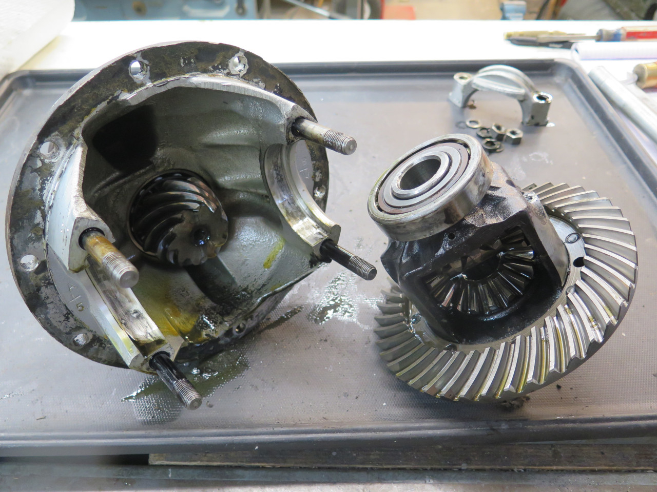
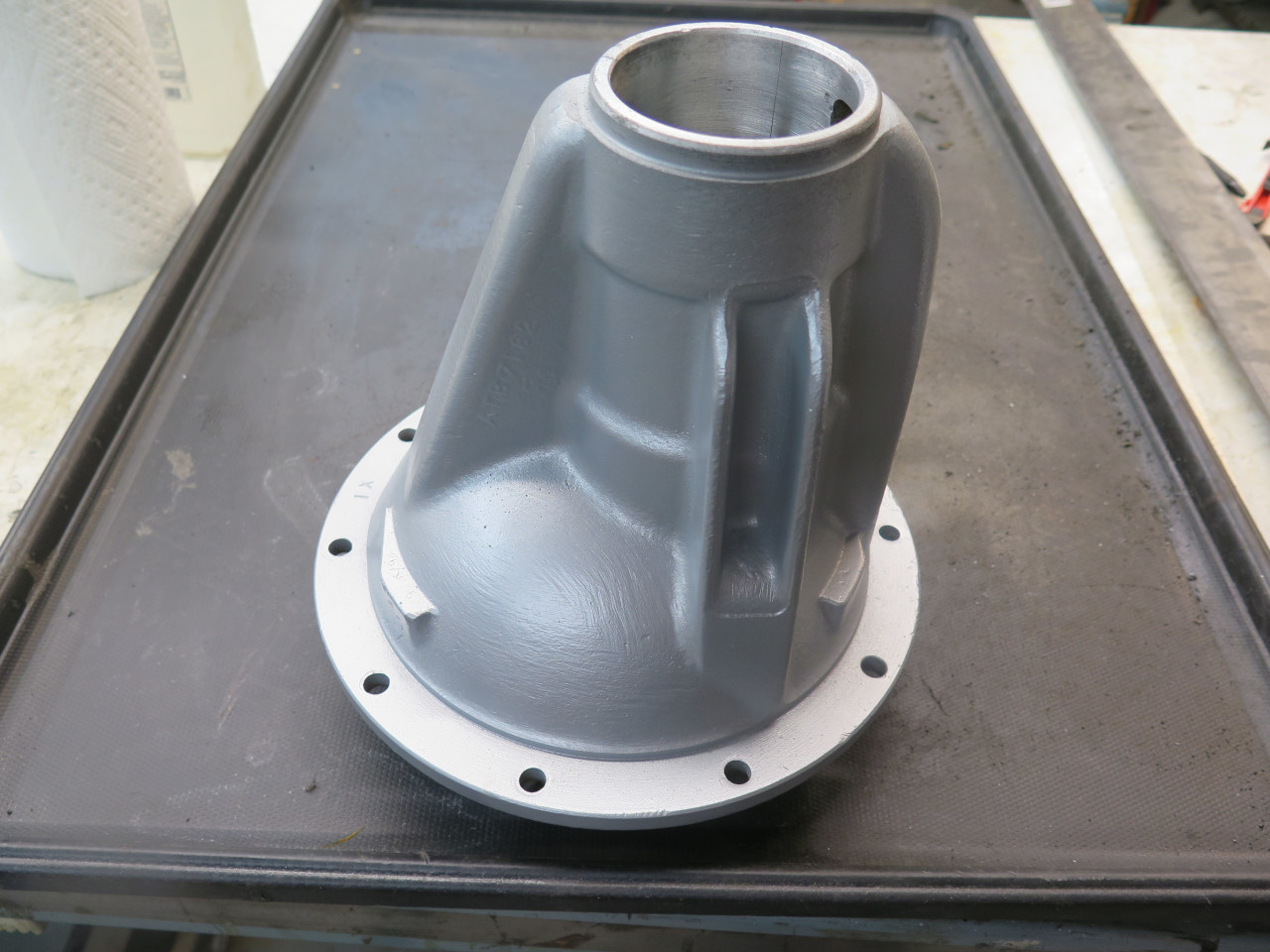
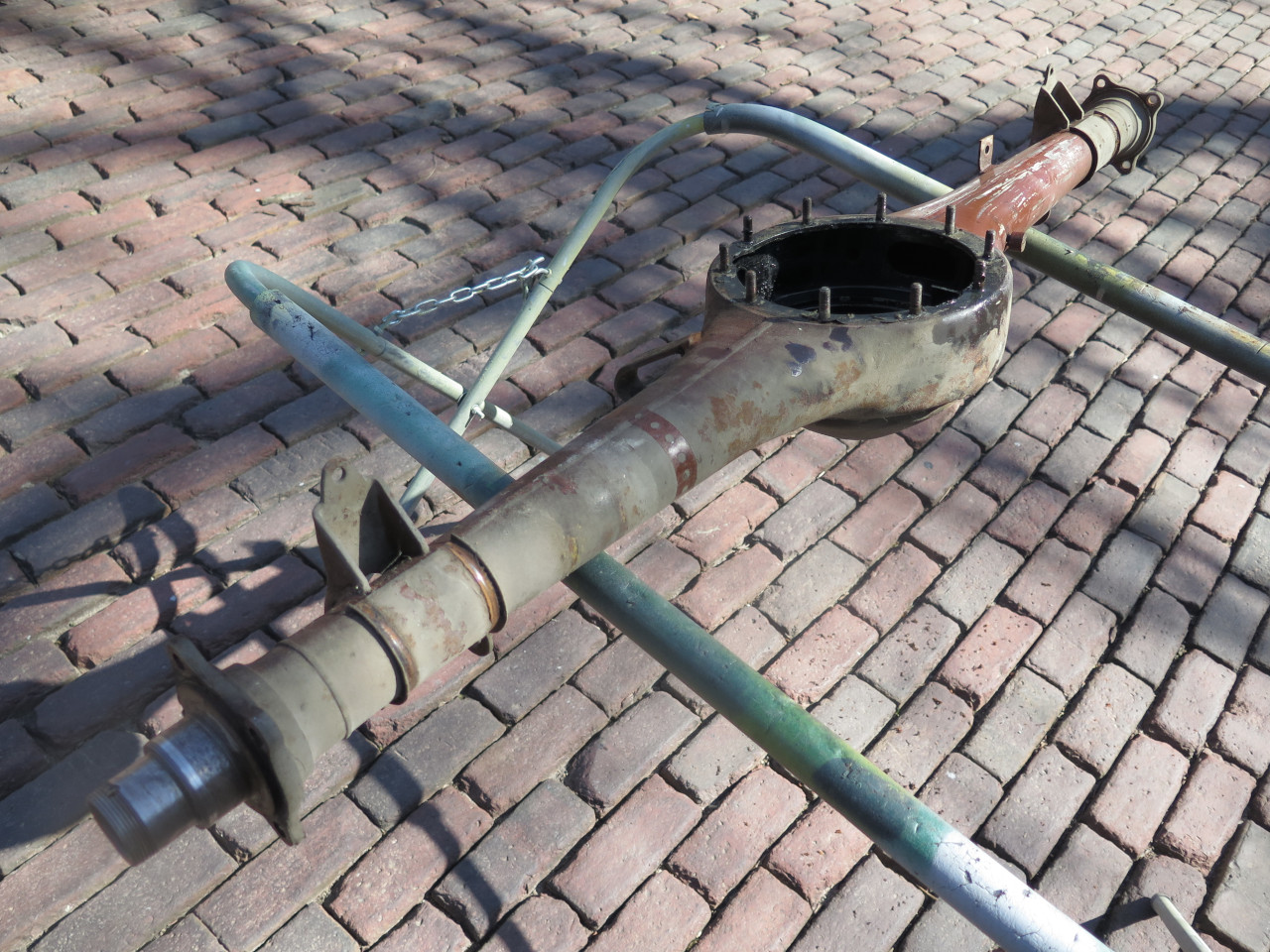
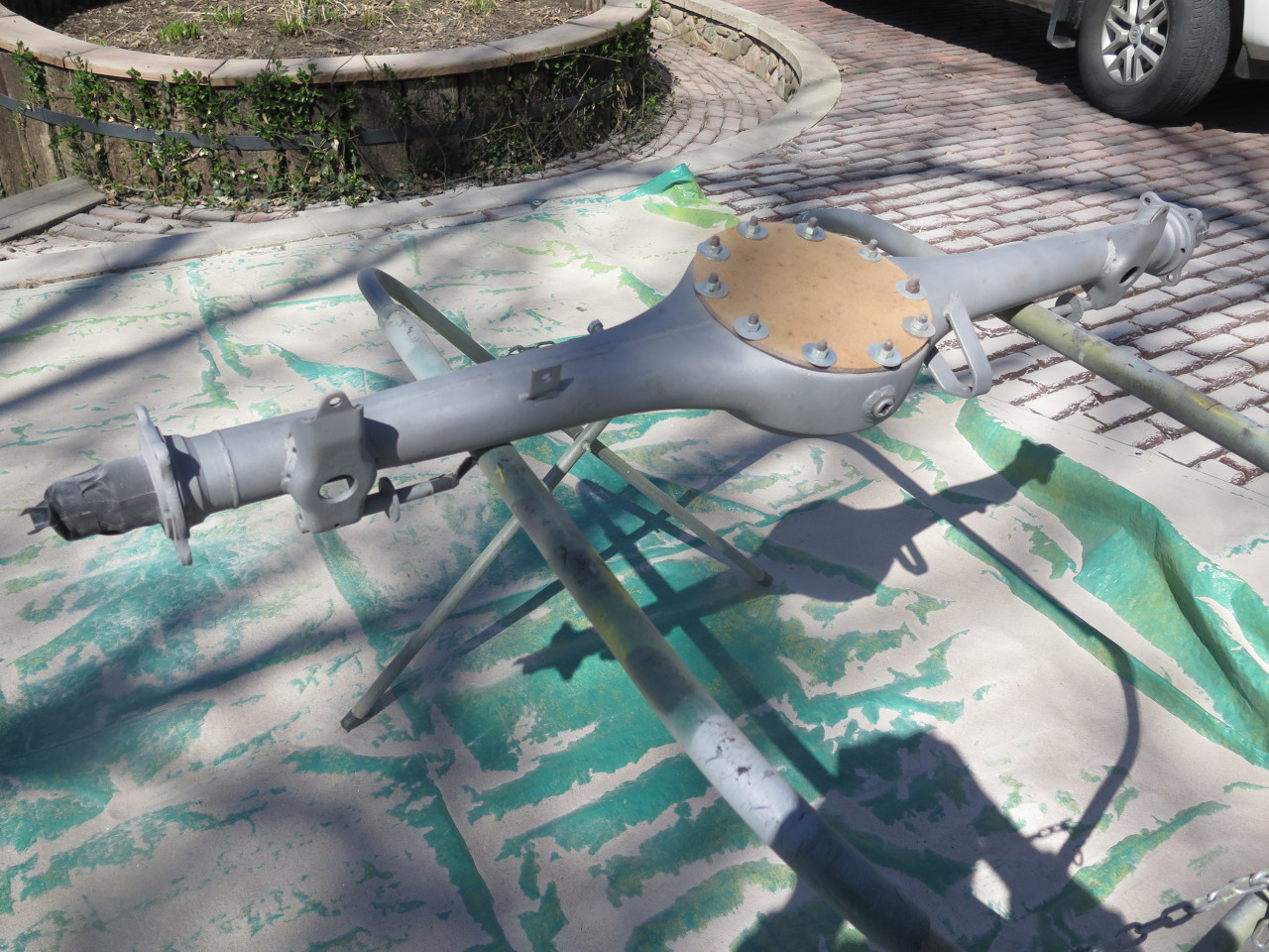
This is the rear end assembly as it dropped from the car.
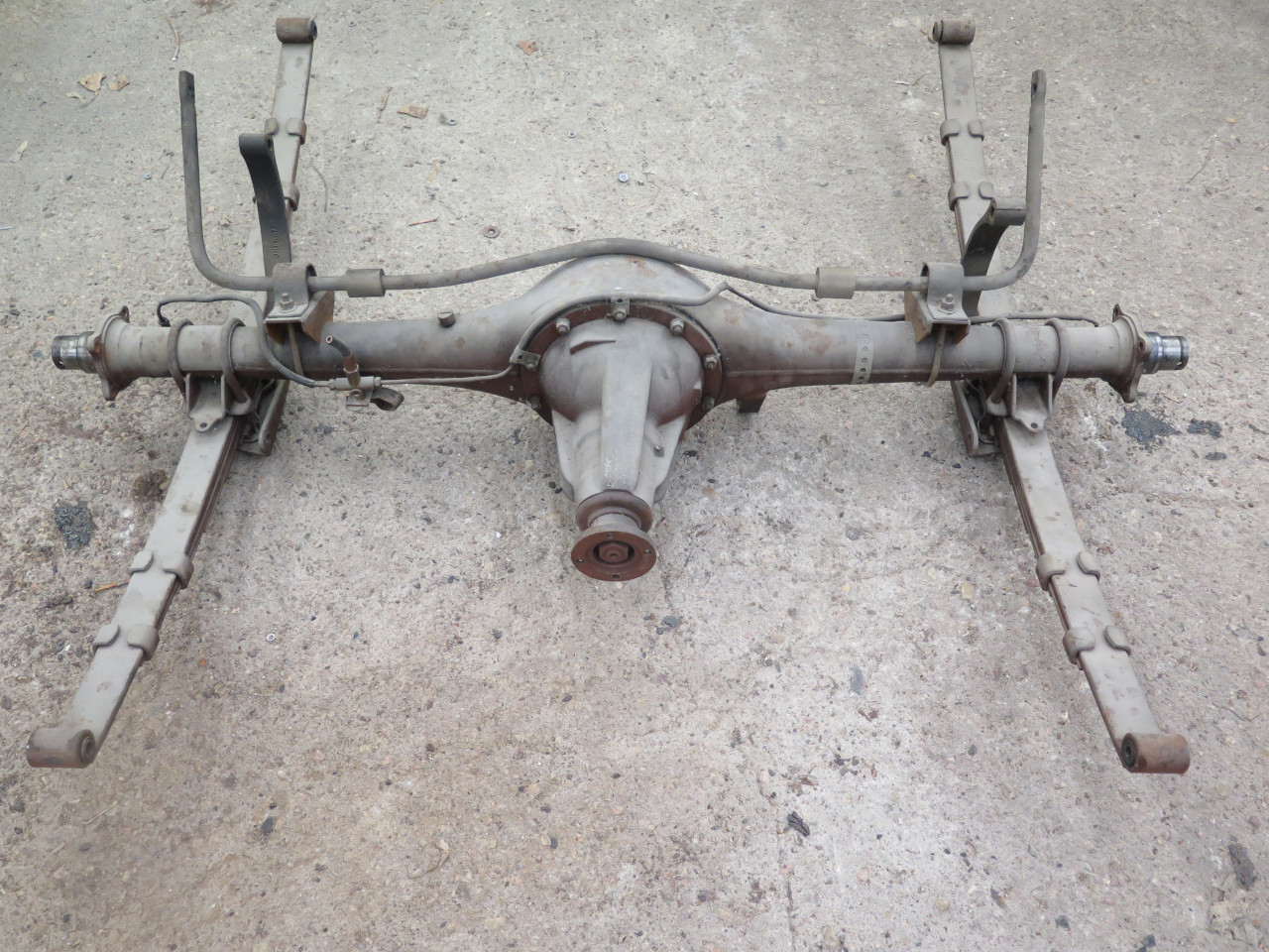
Stripping off the aftermarket rear sway bar, the springs, and the brake
plumbing left a simpler lump. The actual axle shafts had been
previously removed with the hubs.
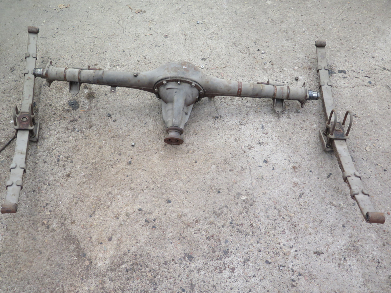
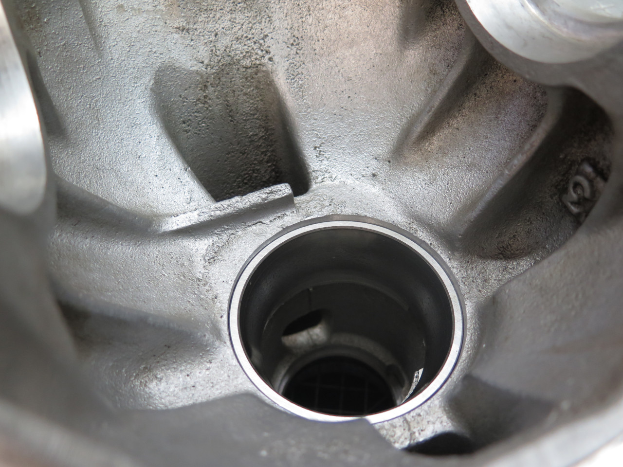
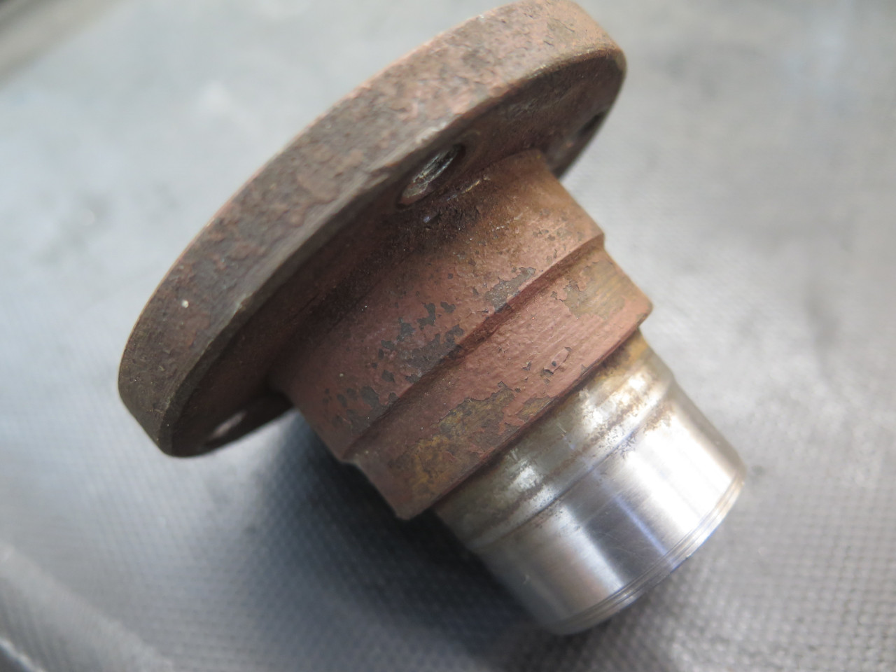
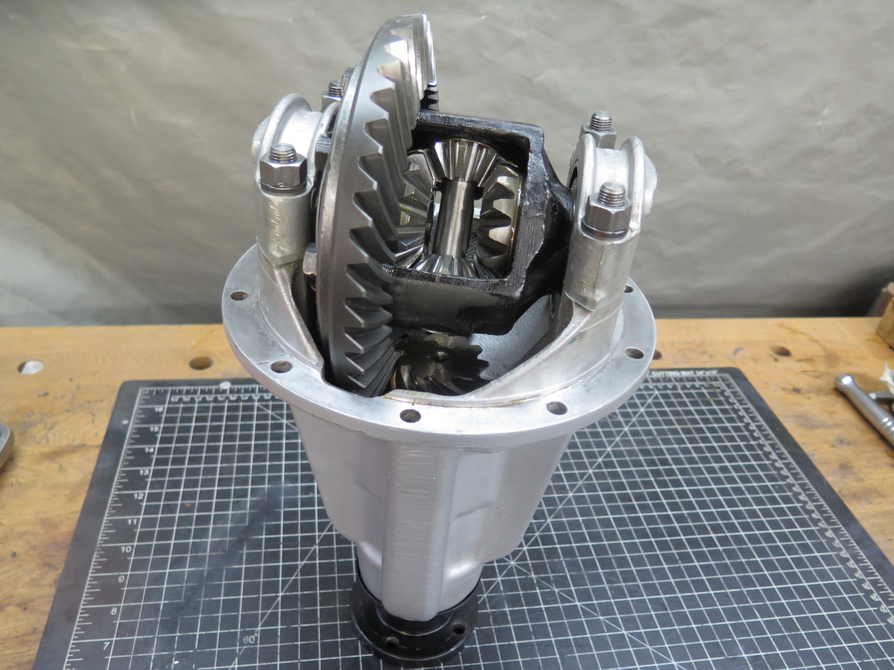
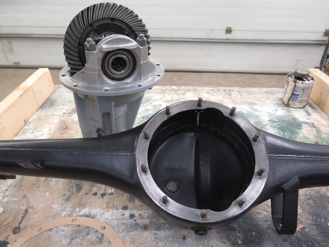
The working guts of the rear axle are all contained in this nose piece. I pulled it of and took it down to the shop.
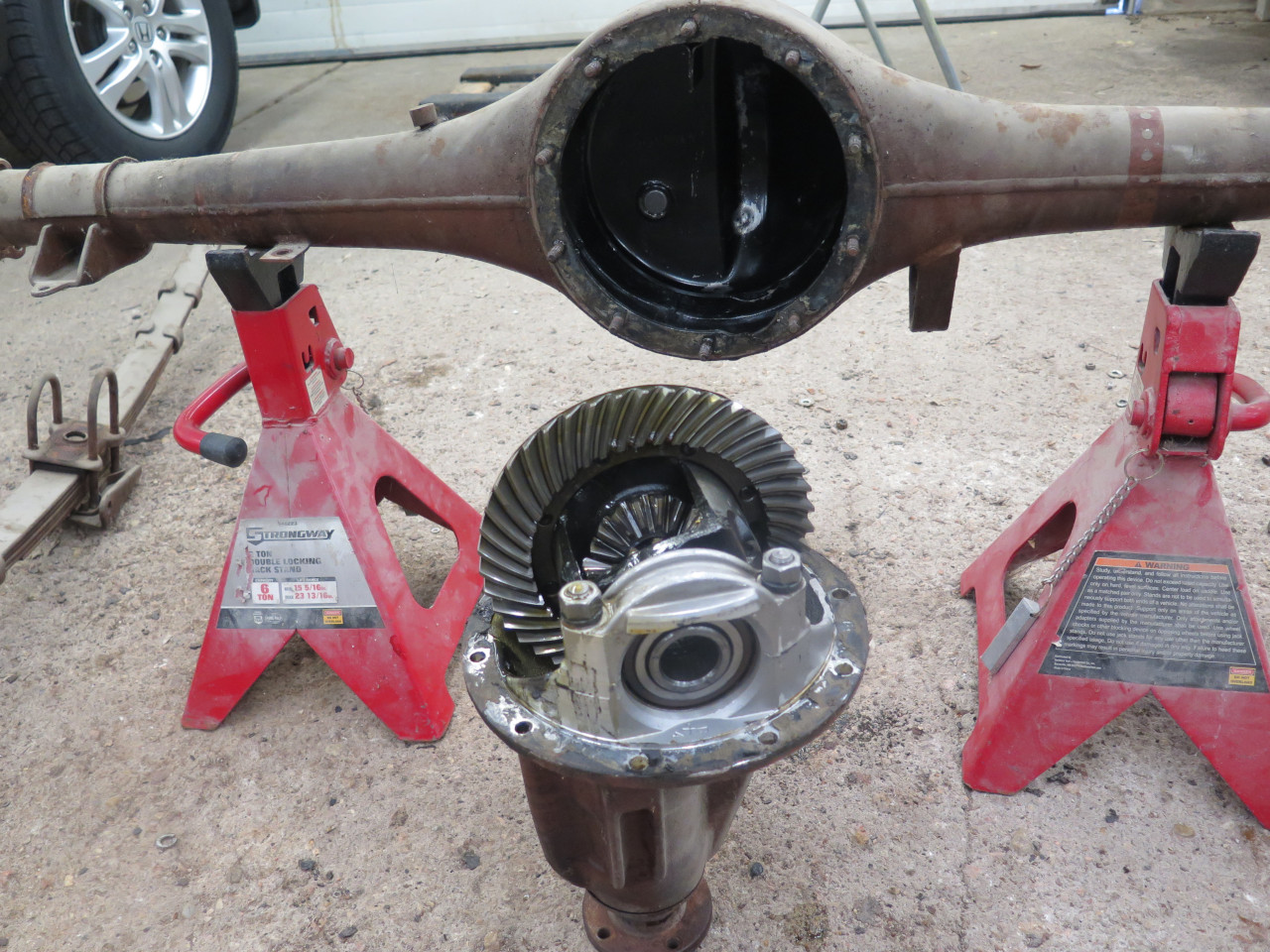
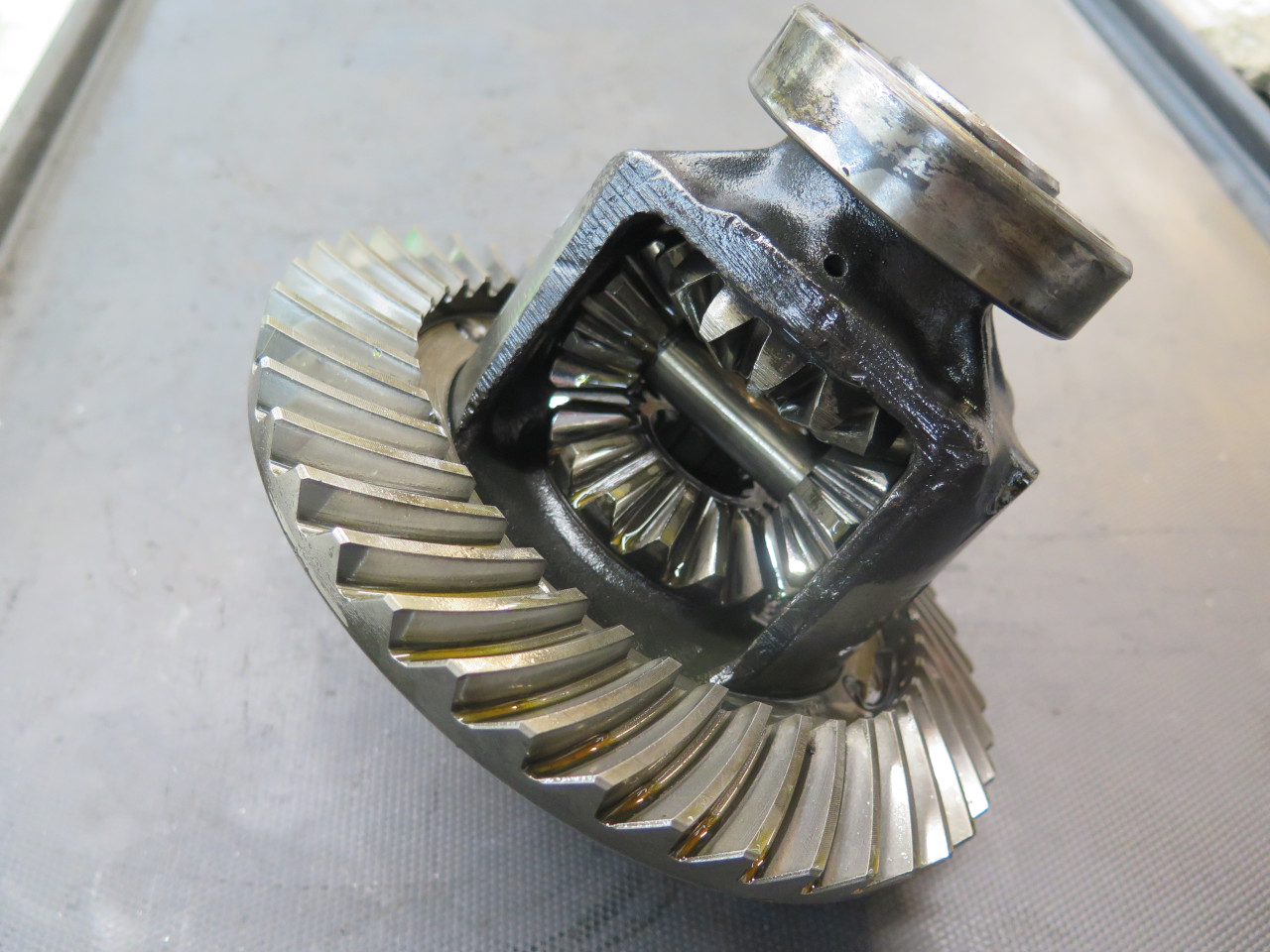
My first impression on looking at the innards was that it was
surprisingly clean and I saw no obvious signs of wear. I did a
couple of quick initial checks: Crown-pinion backlash was
minimal. Differential gear backlash was very small. Pinion
preload seemed loose.
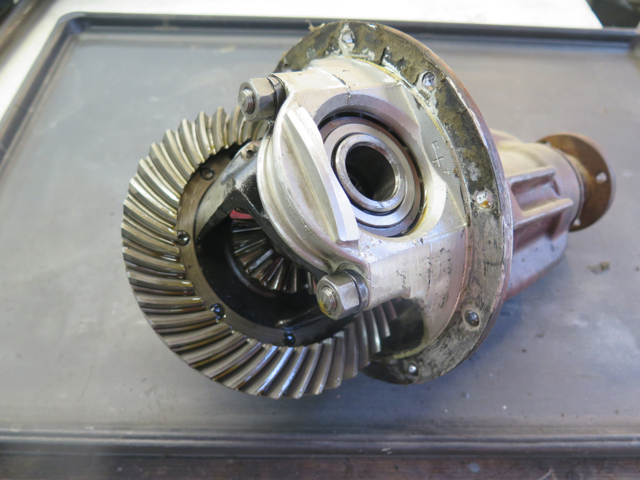
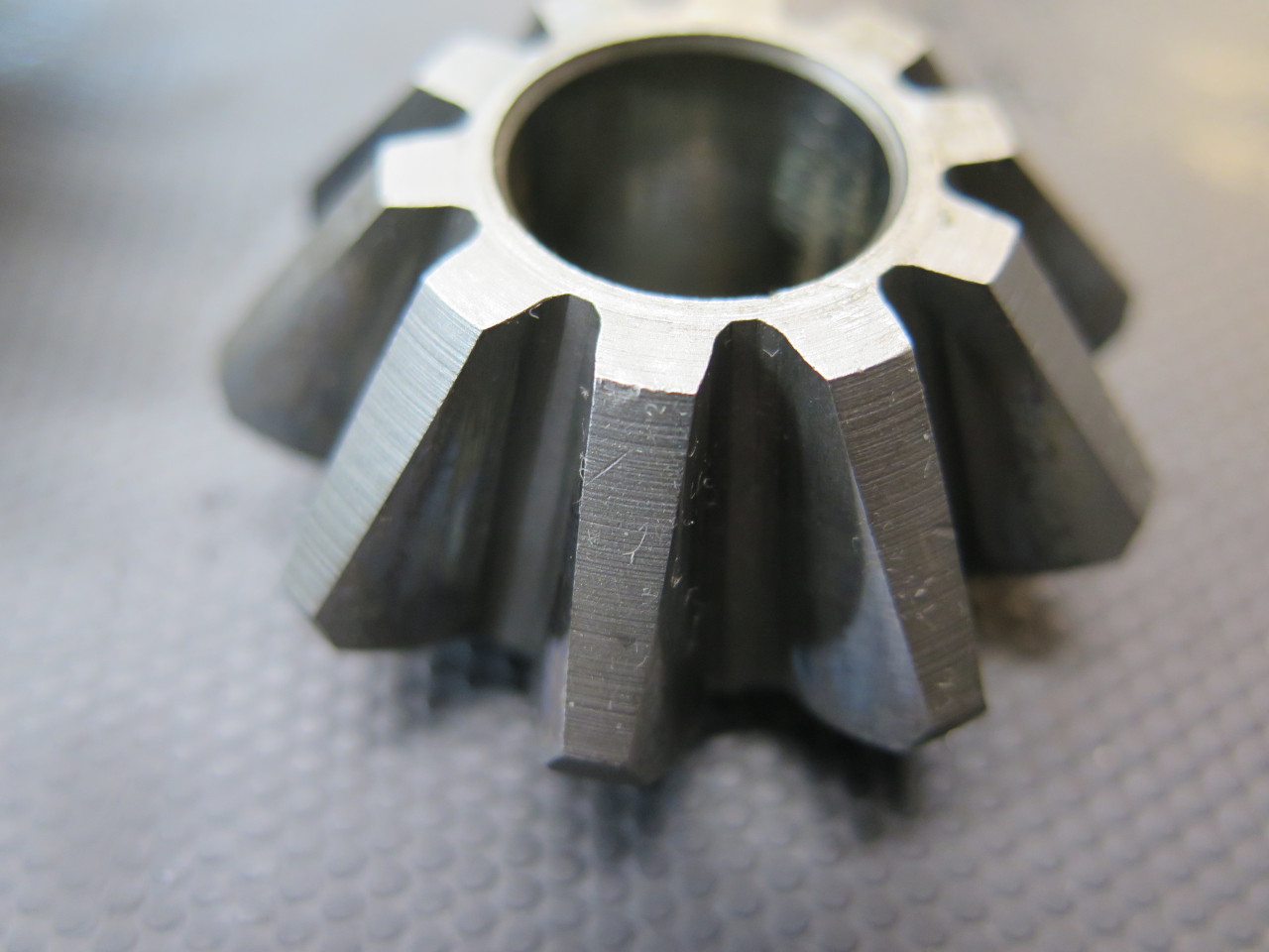
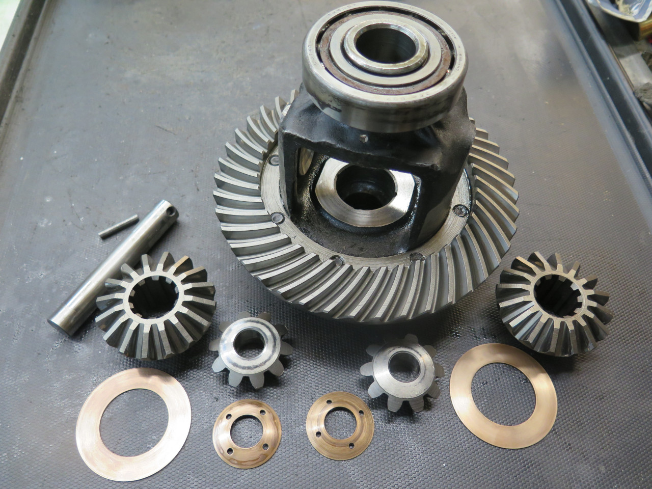
I pulled out the "differential cage" from the carrier body.
Knocking out a little keeper pin allows the planet gear shaft to be
extracted. The shaft showed some polishing wear, but nothing I
could feel or measure.

Pulling all the differential gears, the bronze thrust washers looked nearly new.
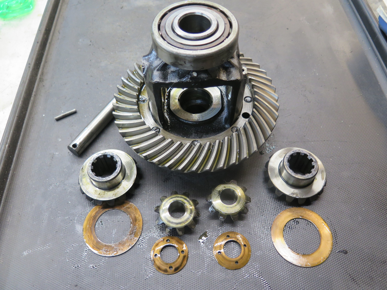
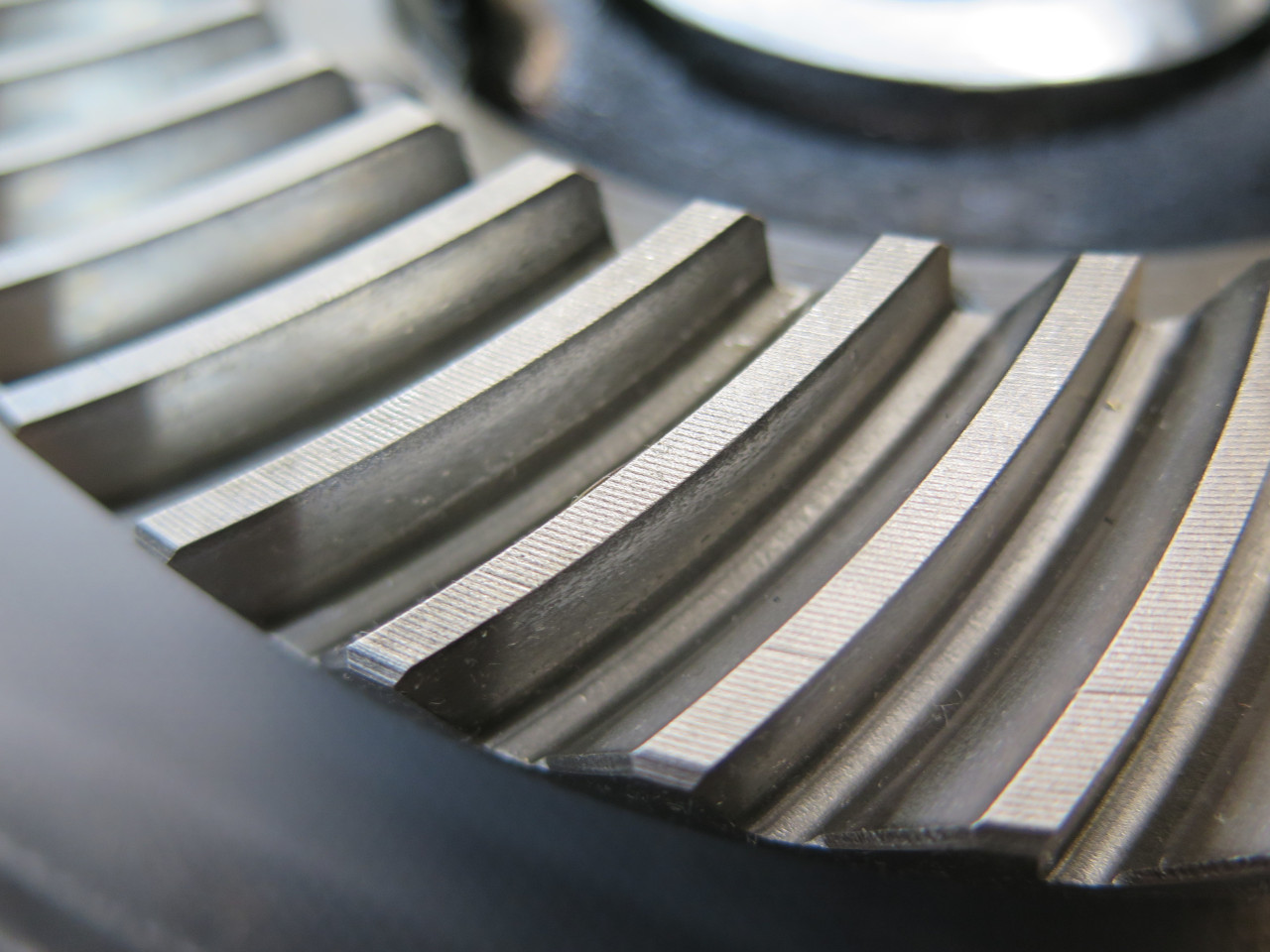
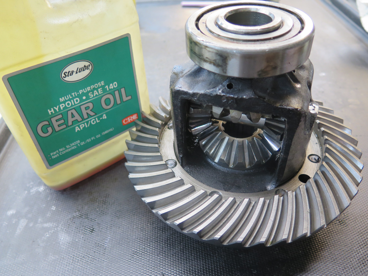
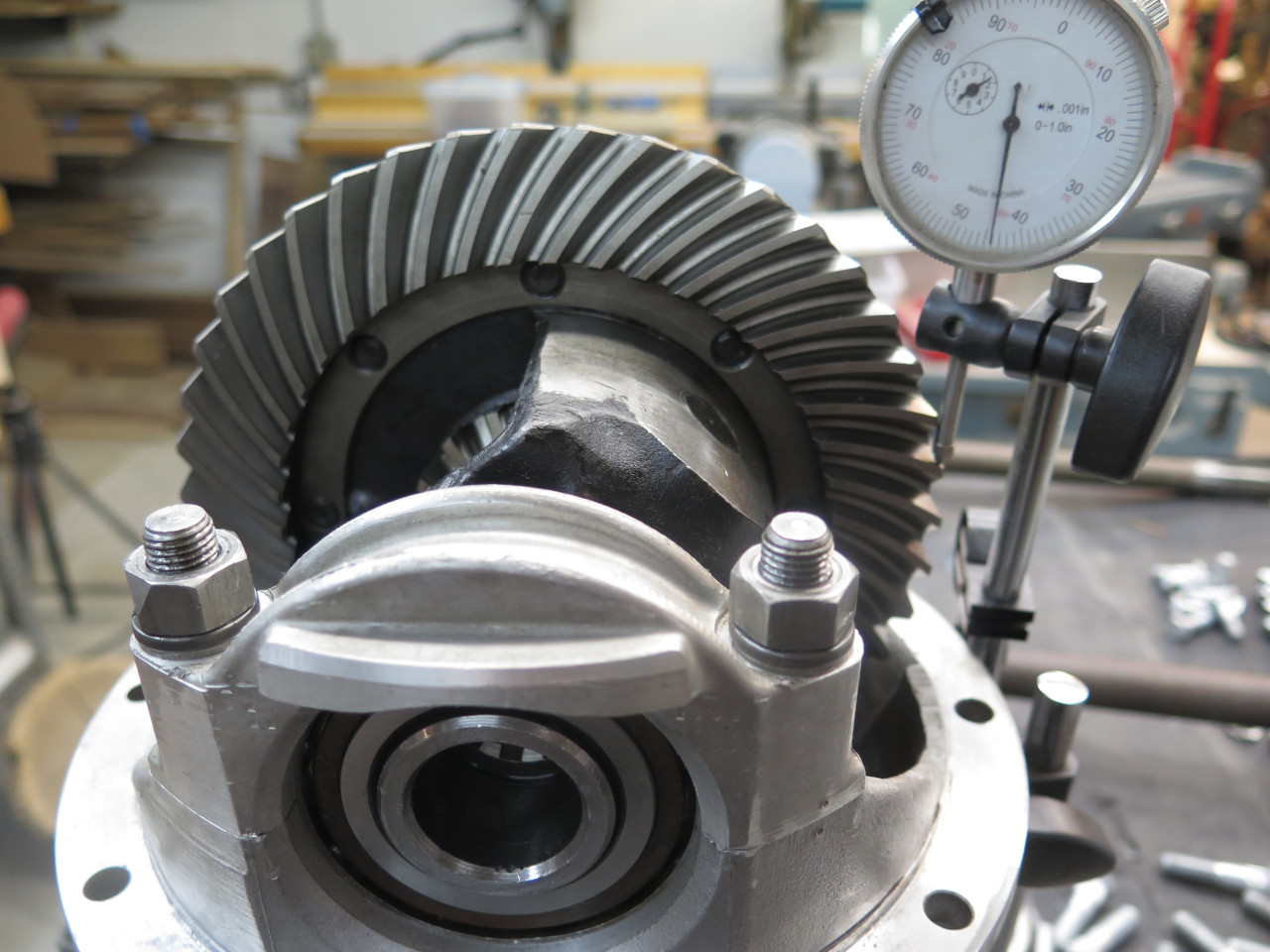
Close inspection of the differential and crown gears showed a remarkable lack of visible wear.

The differential cage bearings felt smooth and tight, so I just put
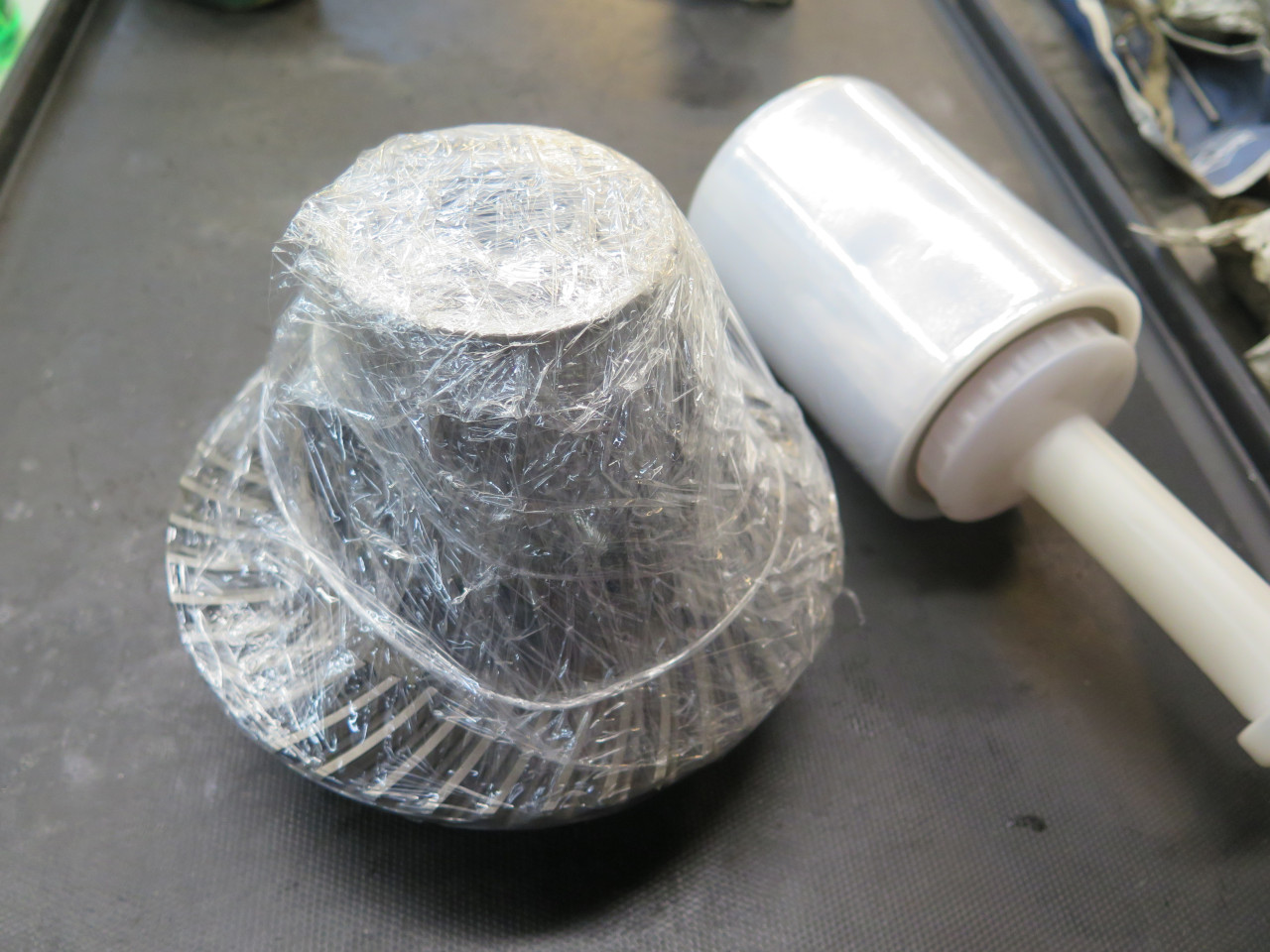
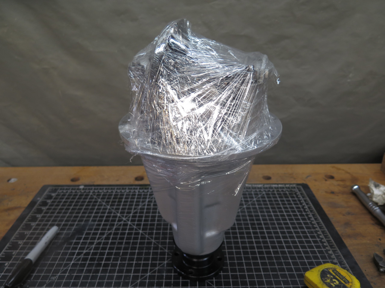
everything back together with no new parts. I wrapped the
differential assembly in plastic to keep shop dust and grit out of it
while I tended to the rest of the rear end.
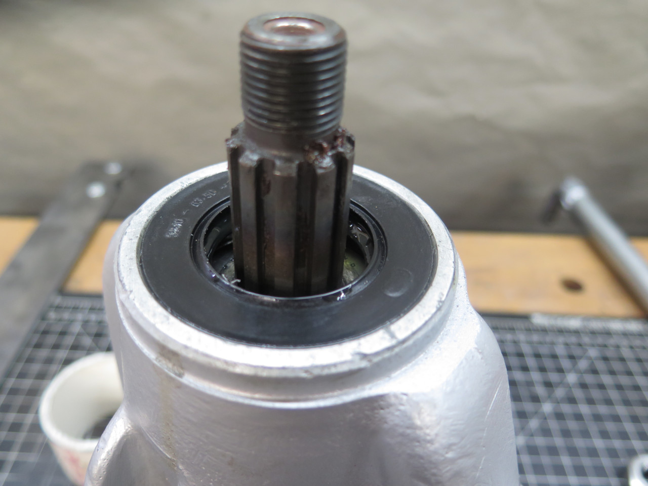
This brought me to the pinion gear, which was still in the
carrier. Since the pinion preload seemed off, it had to come
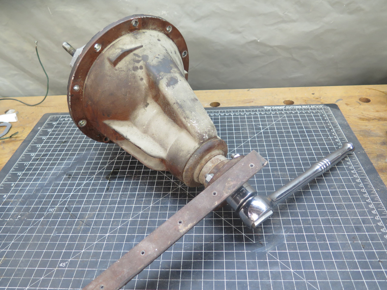
out. There is a serious nut holding it in.
The biggest challenge to removing that nut is holding the flange
stationary. I was really surprised that the shop manual didn't
refer to a special factory tool for this, instead advising to hold the
input flange in a vice. That seemed overly barbaric to me, so I
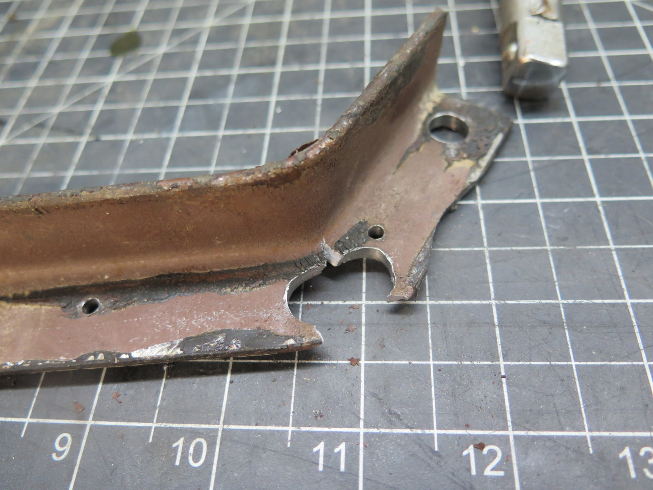
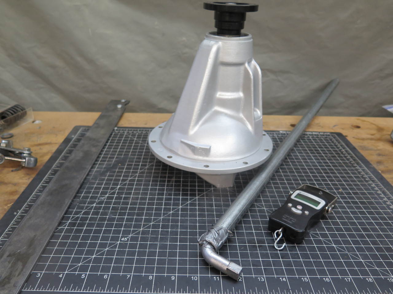
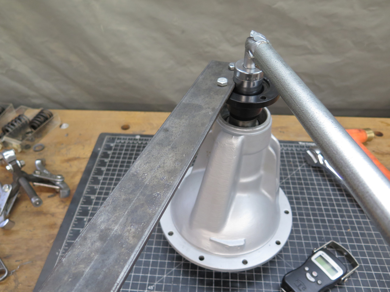
fashioned the tool the factory neglected. It's just a three foot
length of angle iron with two holes at one end that match two of the
holes in the pinion flange. Version 1.0 failed. Version 2.0
worked fine.
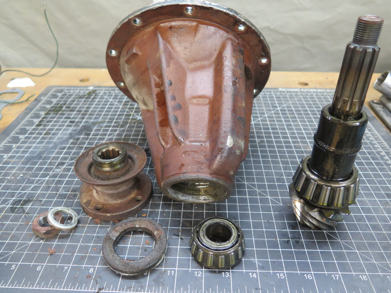
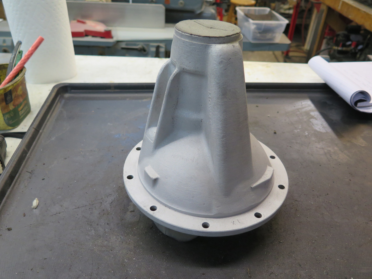
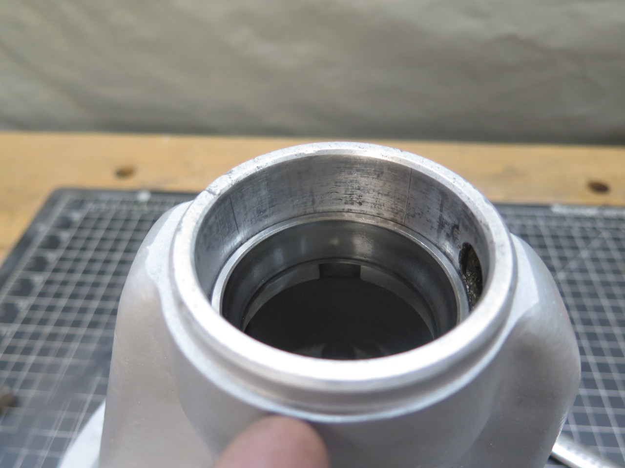
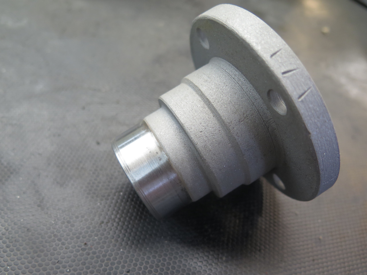
I put the pinion parts aside to focus on the carrier body. It got cleaned, blasted, powder coated, and then cleaned again.
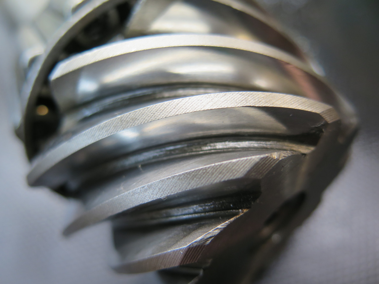
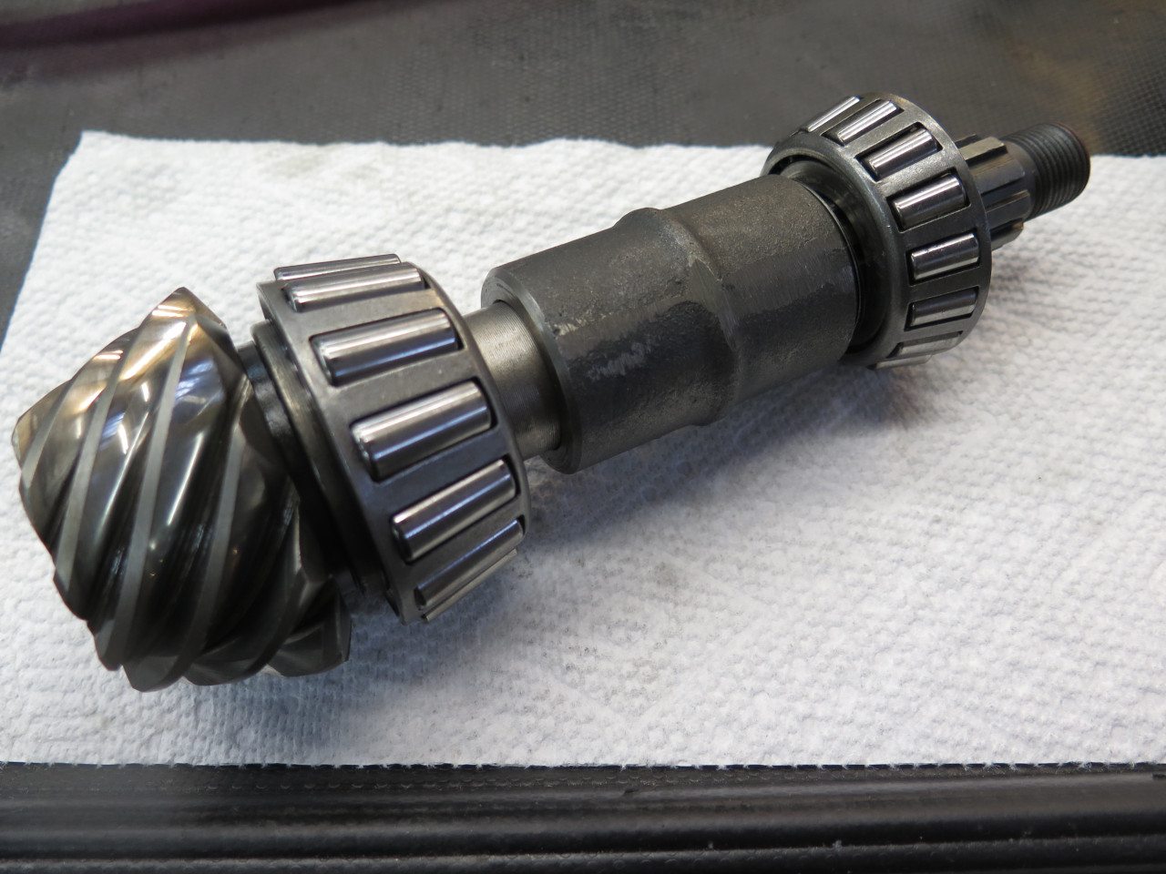
The pinion assembly looked just as good as the differential parts.
The bearings were smooth, and the pinion teeth looked pristine. I
resolved to re-use all the parts.
But there was the matter of the preload. First task was to
reinstall the two bearing outer races. I made these two pucks to
fit the races so that a threaded rod could pull bithg races into
position at the same time without any hammer brutality.
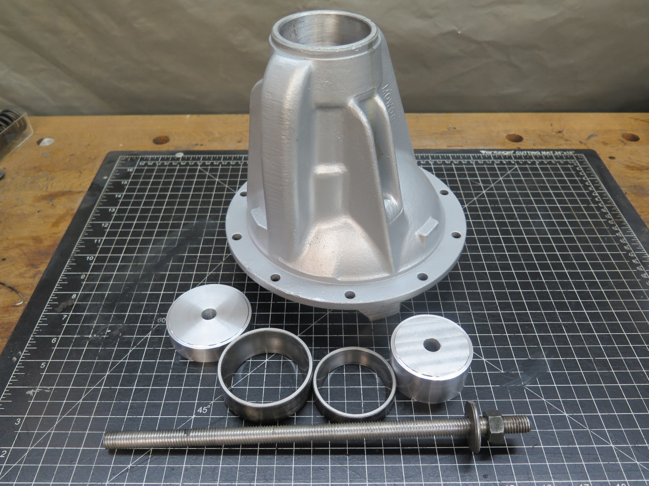
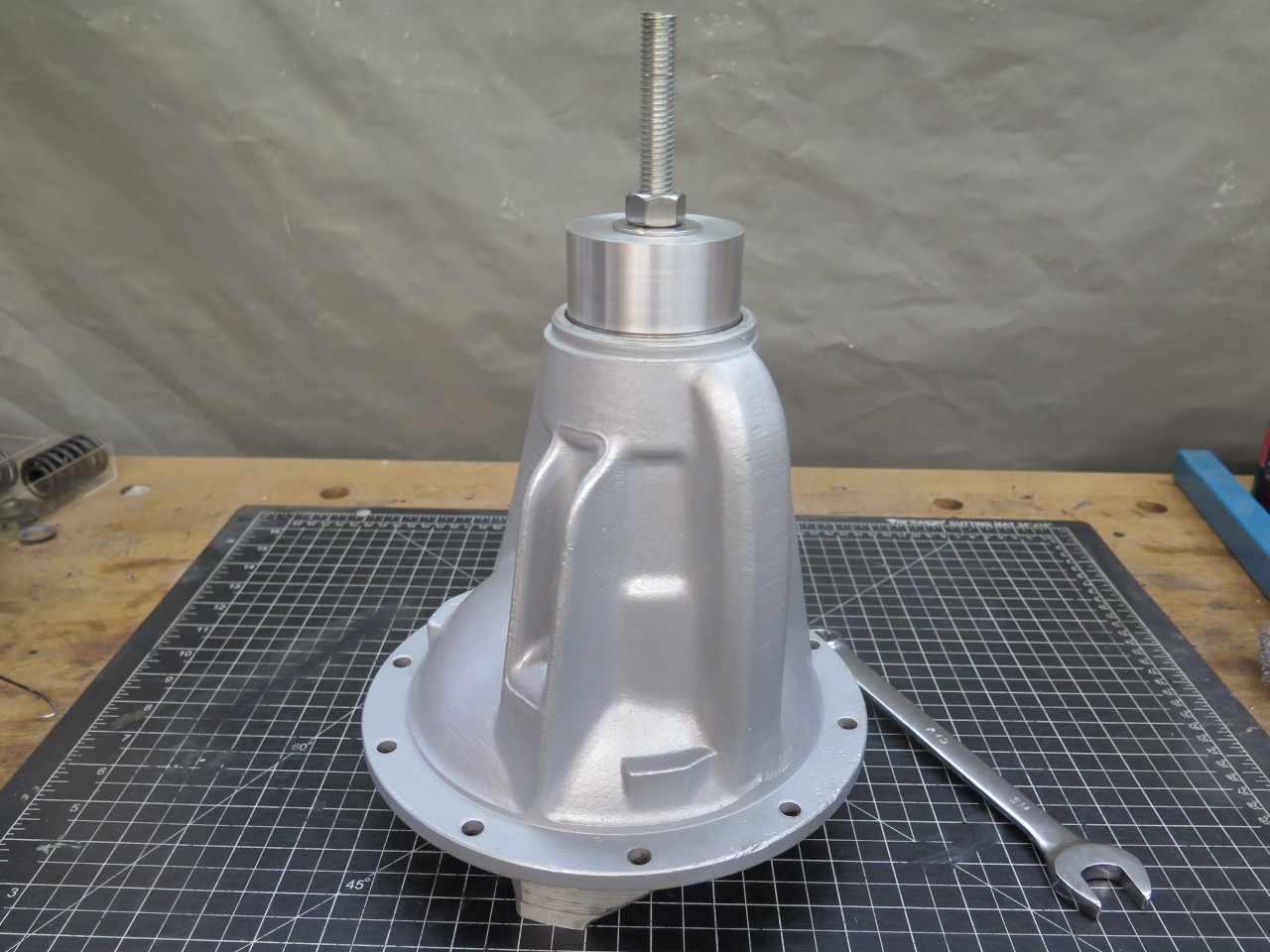
They went home without too much complaint.
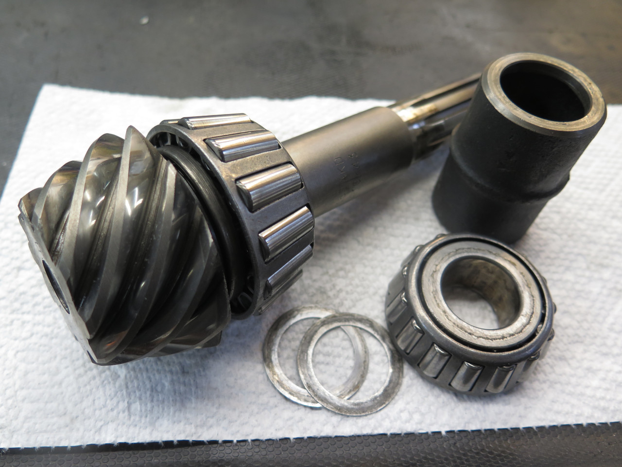
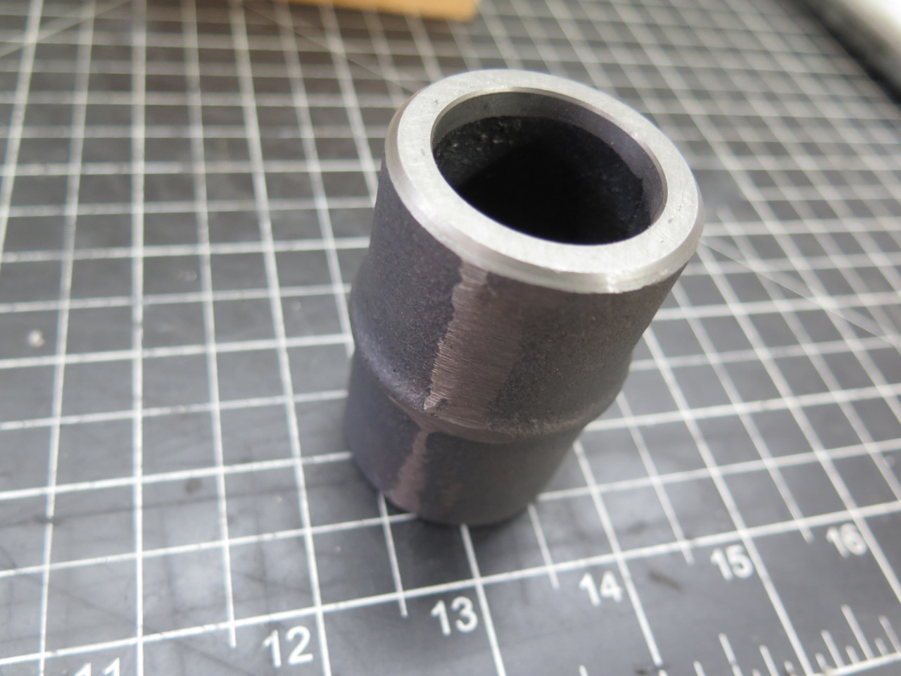
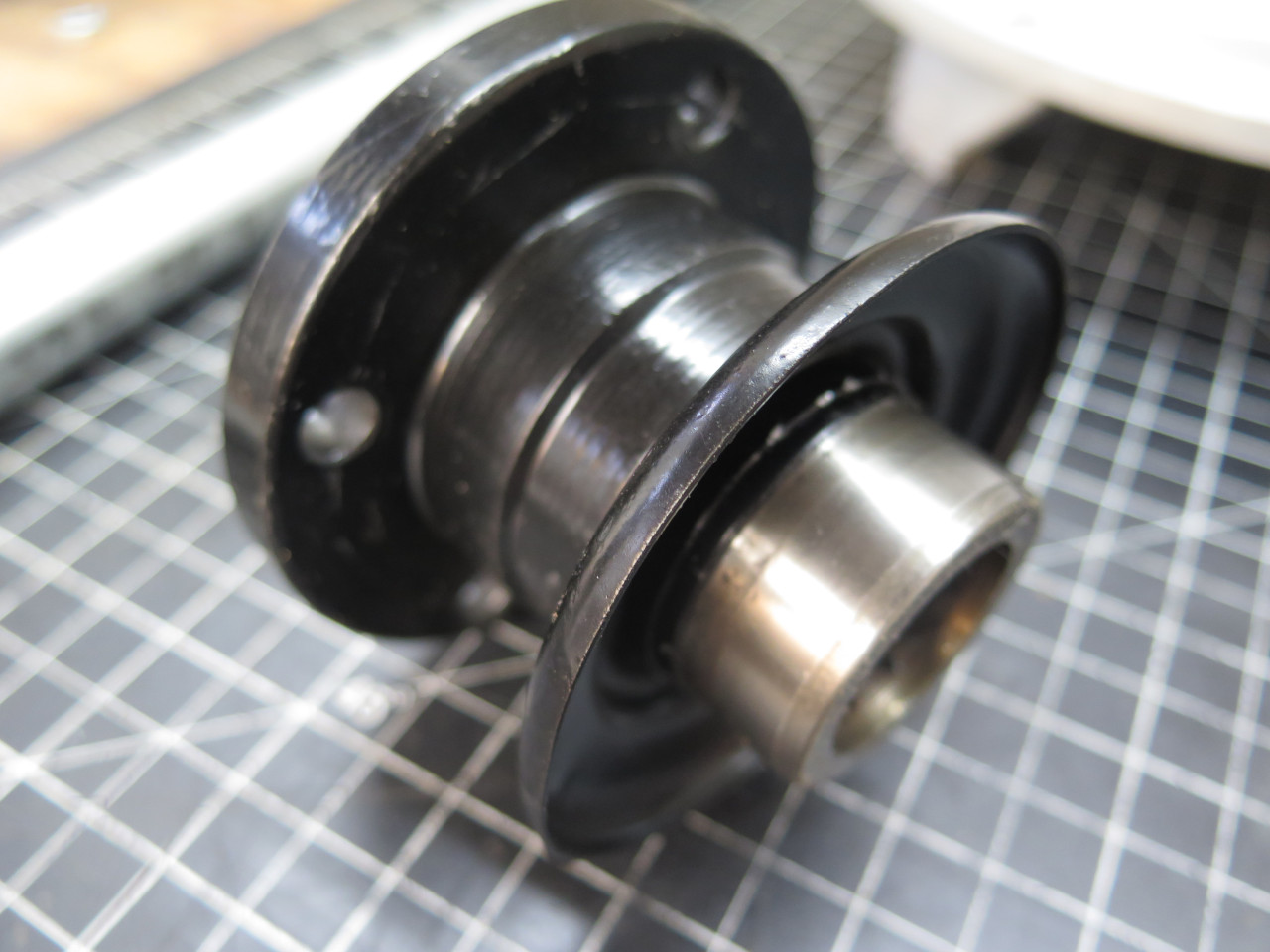
The pinion rides on a pair of chunky tapered roller bearings. The
preload is adjusted by setting the distance between the two inner
races. That distance is determined by a barrel shaped distance
piece, and fine tuned with shims.
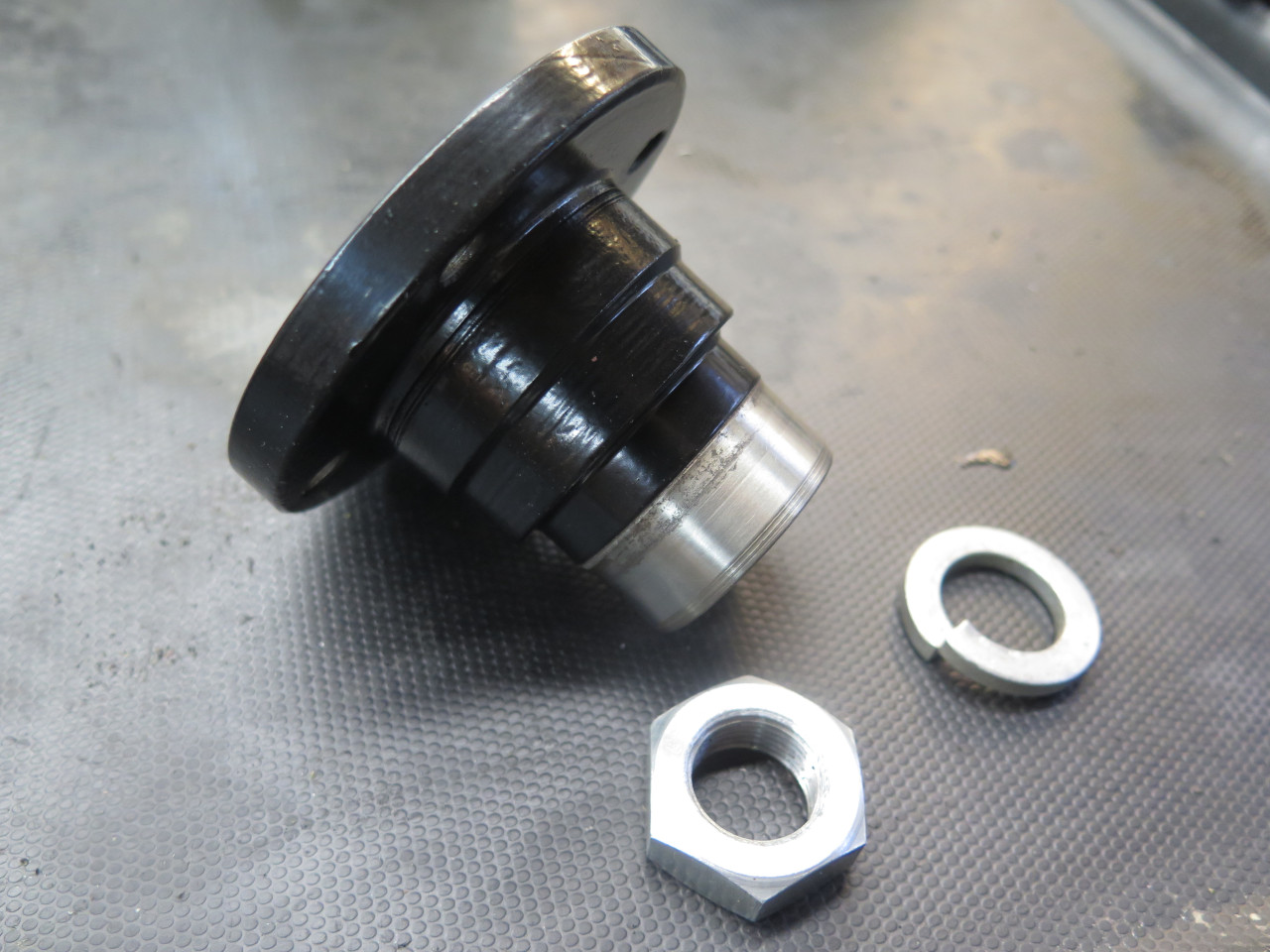
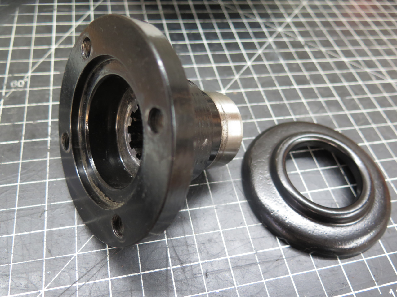
In preparation for the preload process, I cleaned up and powser coated the input flange.
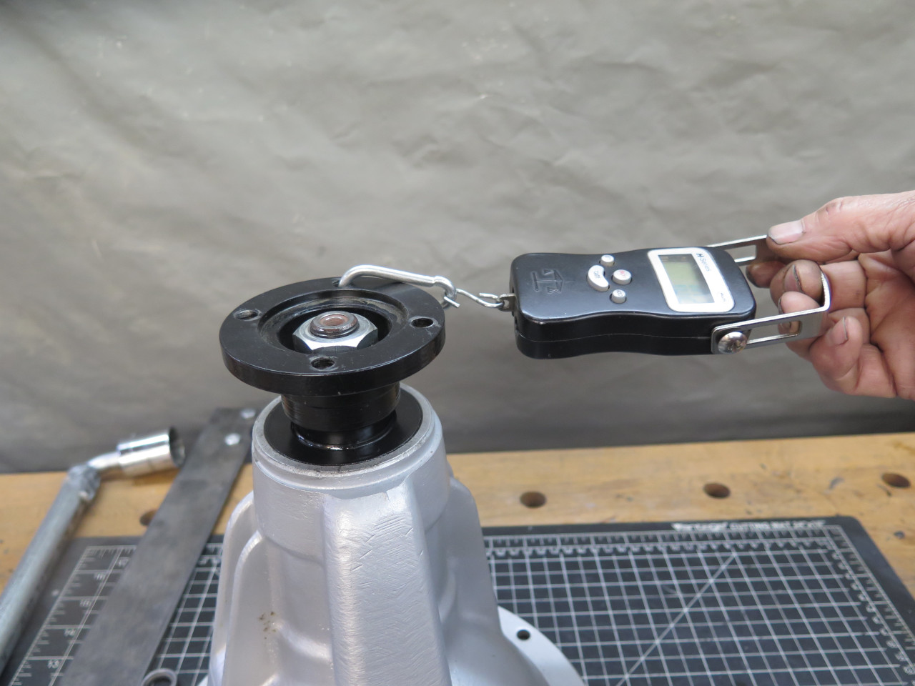
There were two shims in the assembly as I found it--one was 0.006", the
other measured 0.011". Since there was not enough preload, I had
to reduce the spacing. I was under the impression that the spacing
only needed to be reduced by a few thousandths, and that removing the
thinner shim was likely too much. Since I didn't have any shims
that would fit, I decided to just shorten the spacer barrel. It
measured 2.401", and I reduced it to 2.399". This made no
difference, and the preload was still essentially zero. It took
three more iterations to get to the required range of 10-12 inch pounds,
with a final barrel length of 2.395--exactly 0.006" less than where it
started.
Each iteration required undoing the highly torqued pinion nut, pulling
the flange off the shaft, dropping the pinion assembly, skimming the
barrel, reassembling everything, re-torquing to 140 foot pounds, and
measuring the preload. I have two torque wrenches, but neither
goes as high as 140 foot-pounds. Here are the non-factory tools I
used, including the home-brew torque wrench. The three-foot long
cheater only required a pull of around 47 pounds on the far end.
Once the preload was correct, the pinion had to come apart again to install the oil seal.
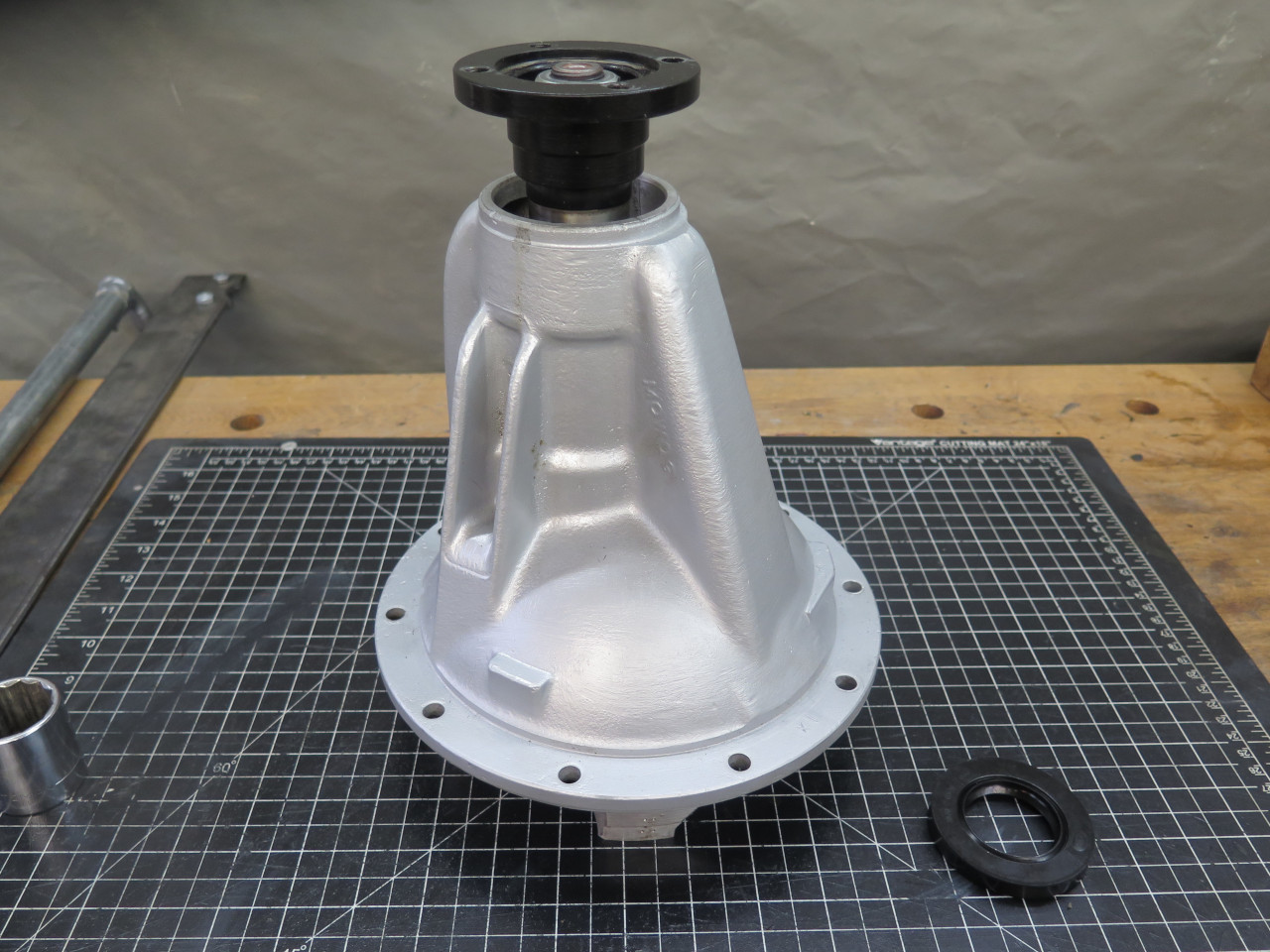
And then once more to install the "dust cover" that I'd forgotten.
So, with the preload set, I retrieved the differential assembly, and popped it in.
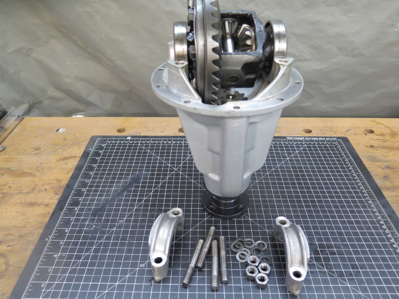
Checked the crown-pinion lash. It was at the top edge of the spec.
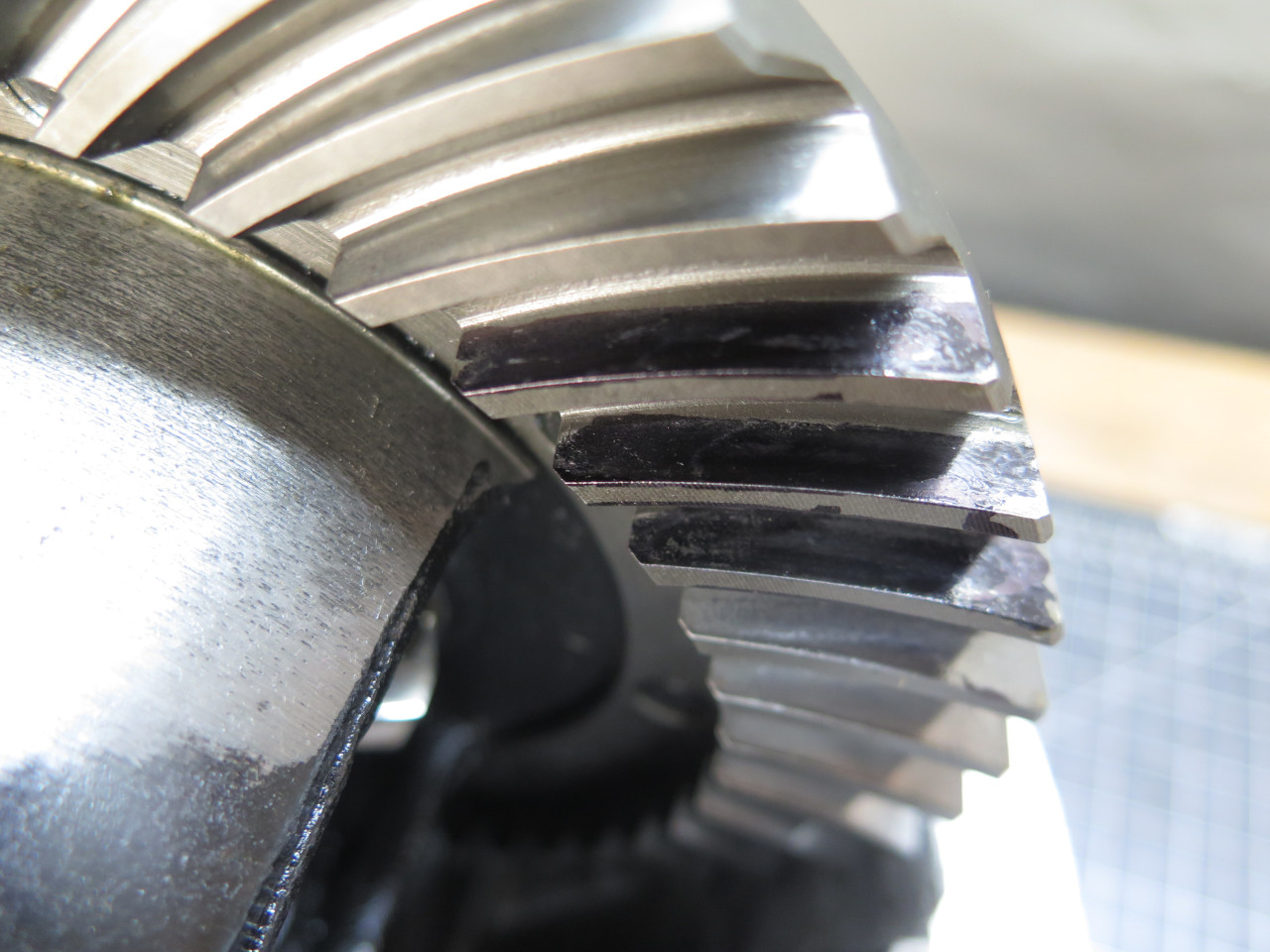
Then checked the pinion-crown mesh. The camera didn't pick it up well, but the contact areas are just in the right place.
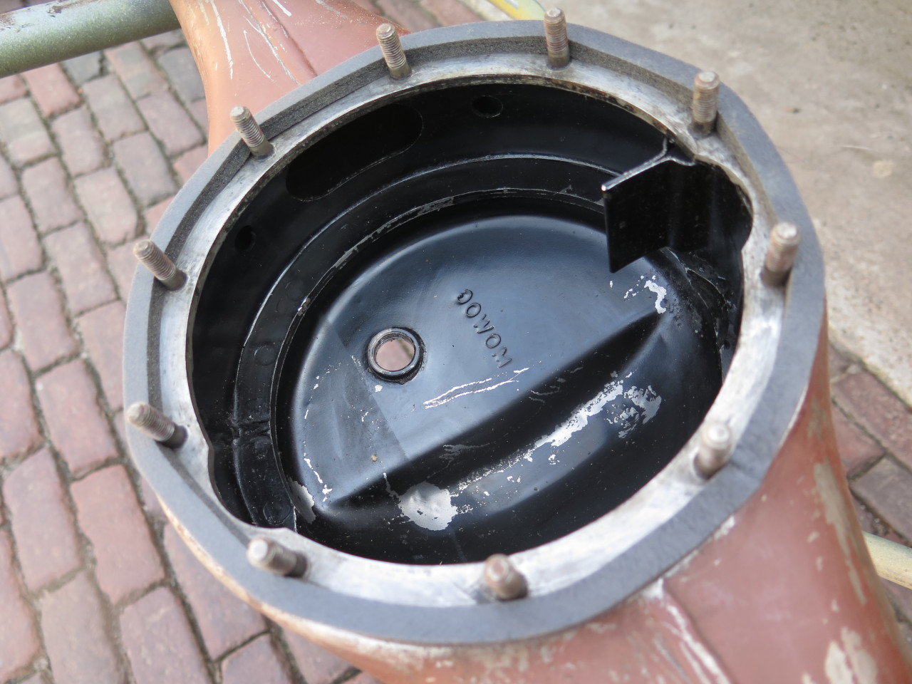
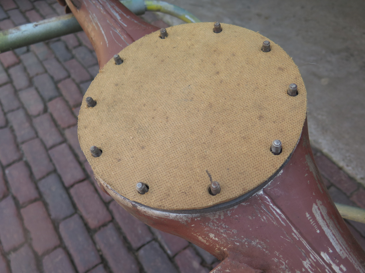
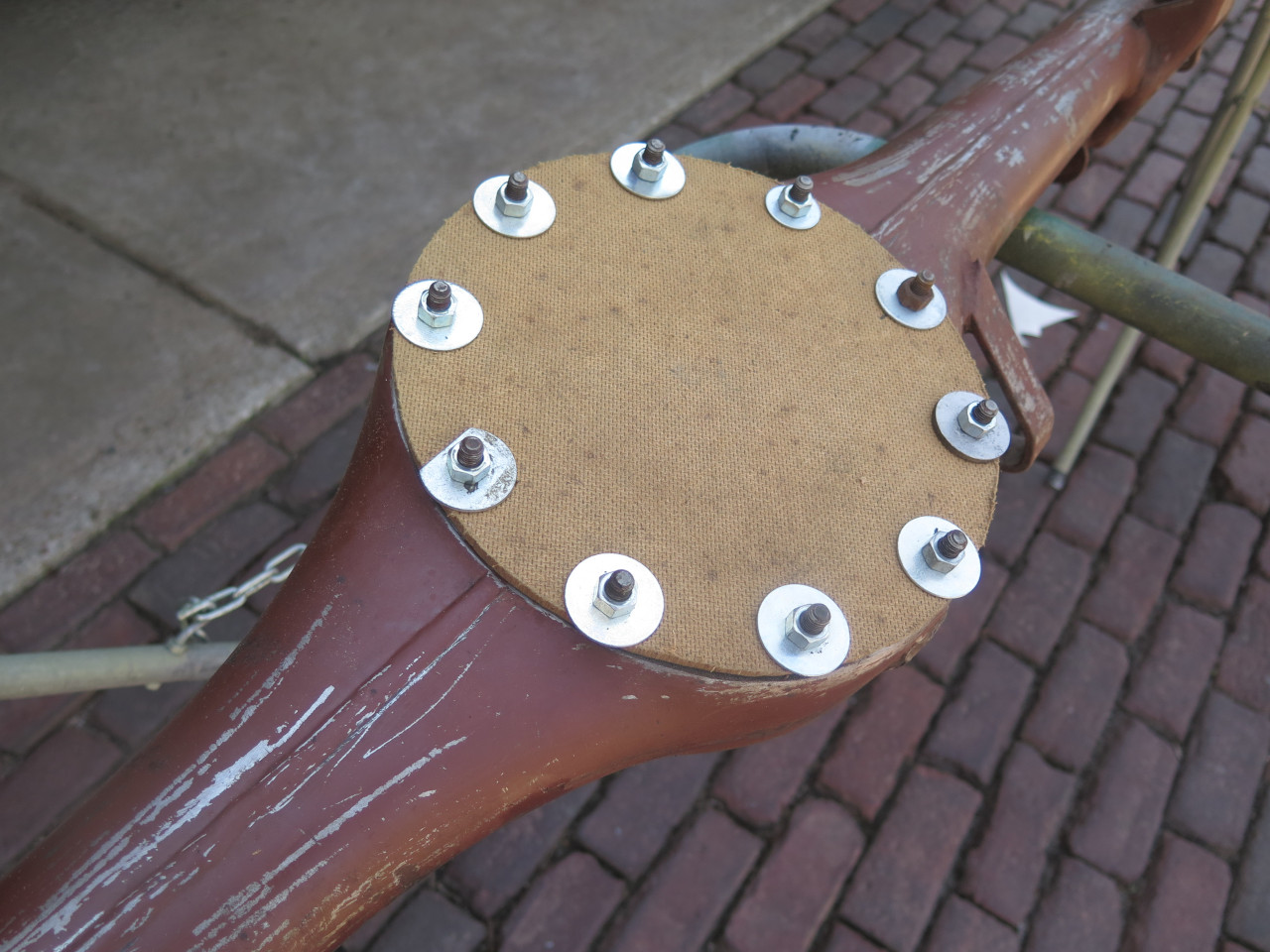
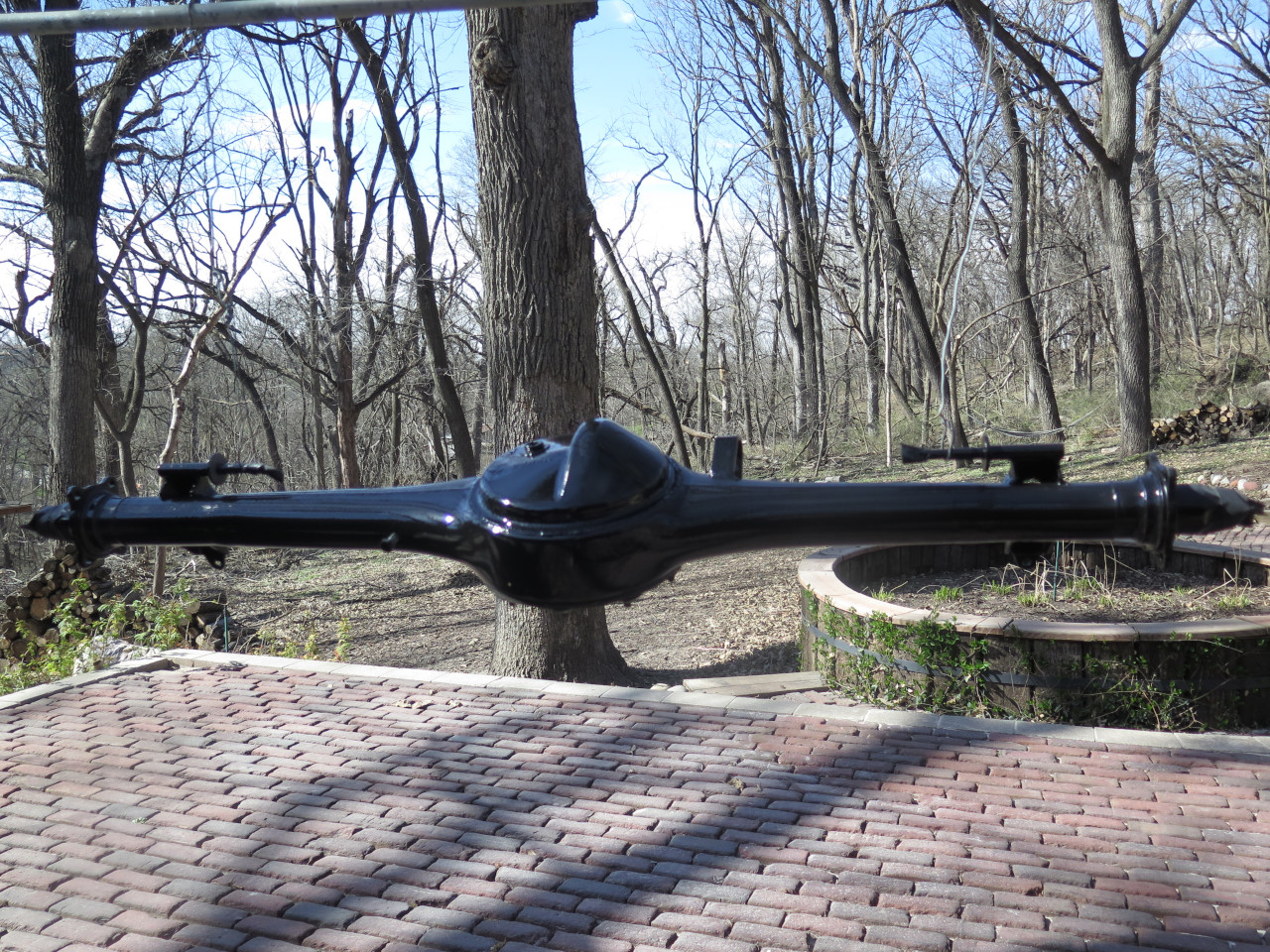
Sealed it up, and went to the garage looking for the rear axle housing. I drug it outside for blasting.
But since I thought that getting blasting grit inside the casing was
probably a bad idea, I spent some effort to seal it up. I plugged
the hub ends and made a bespoke cover for the big mouth. Sealed it
with foam tape.
And blasted away, then some nice epoxy.
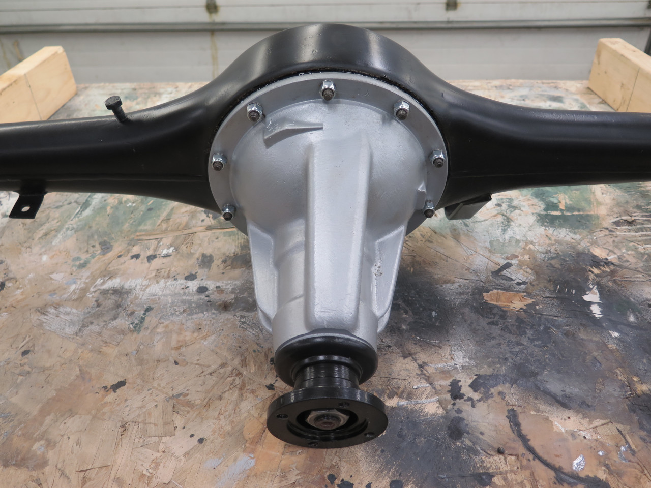
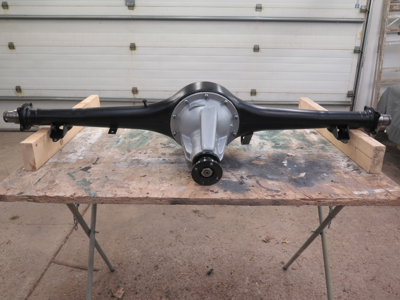
Then it was time to reinstall the guts.
Finally looking respectable.
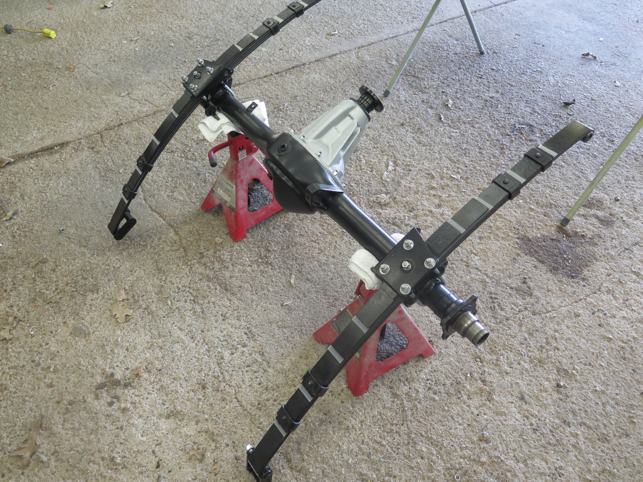
Went and got the recently rebuilt leaf springs.
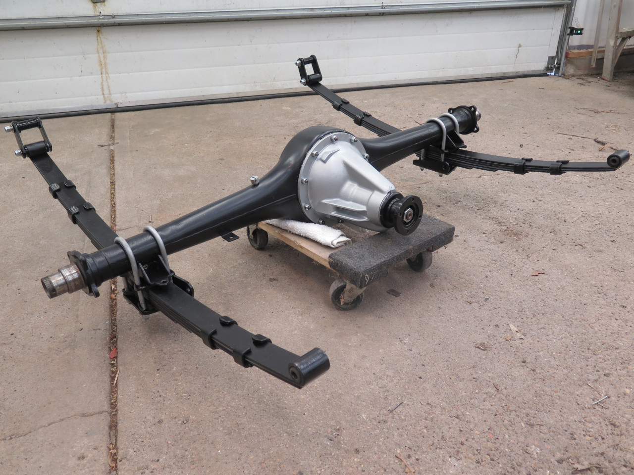
This job took a while, but thanks to the surprisingly good condition of
the internal parts, the cost was next to nothing. I'm thinking
that the rear axle must have been replaced shortly before I got the car,
and I probably put less than 10,000 miles on it. It's
serendipity.!
Comments to Ed at elhollin1@yahoo.com
To my other MGA pages.