To my other MGA pages.
February 23, 2025
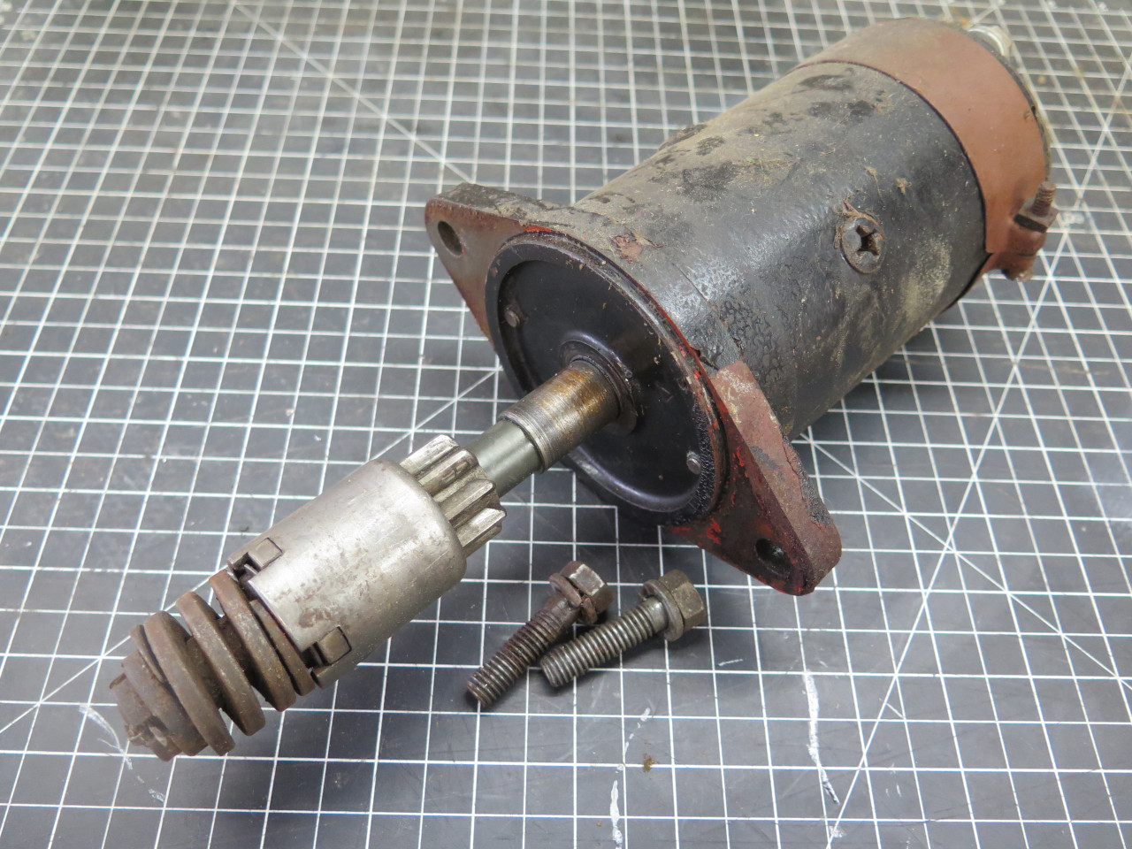
Starter
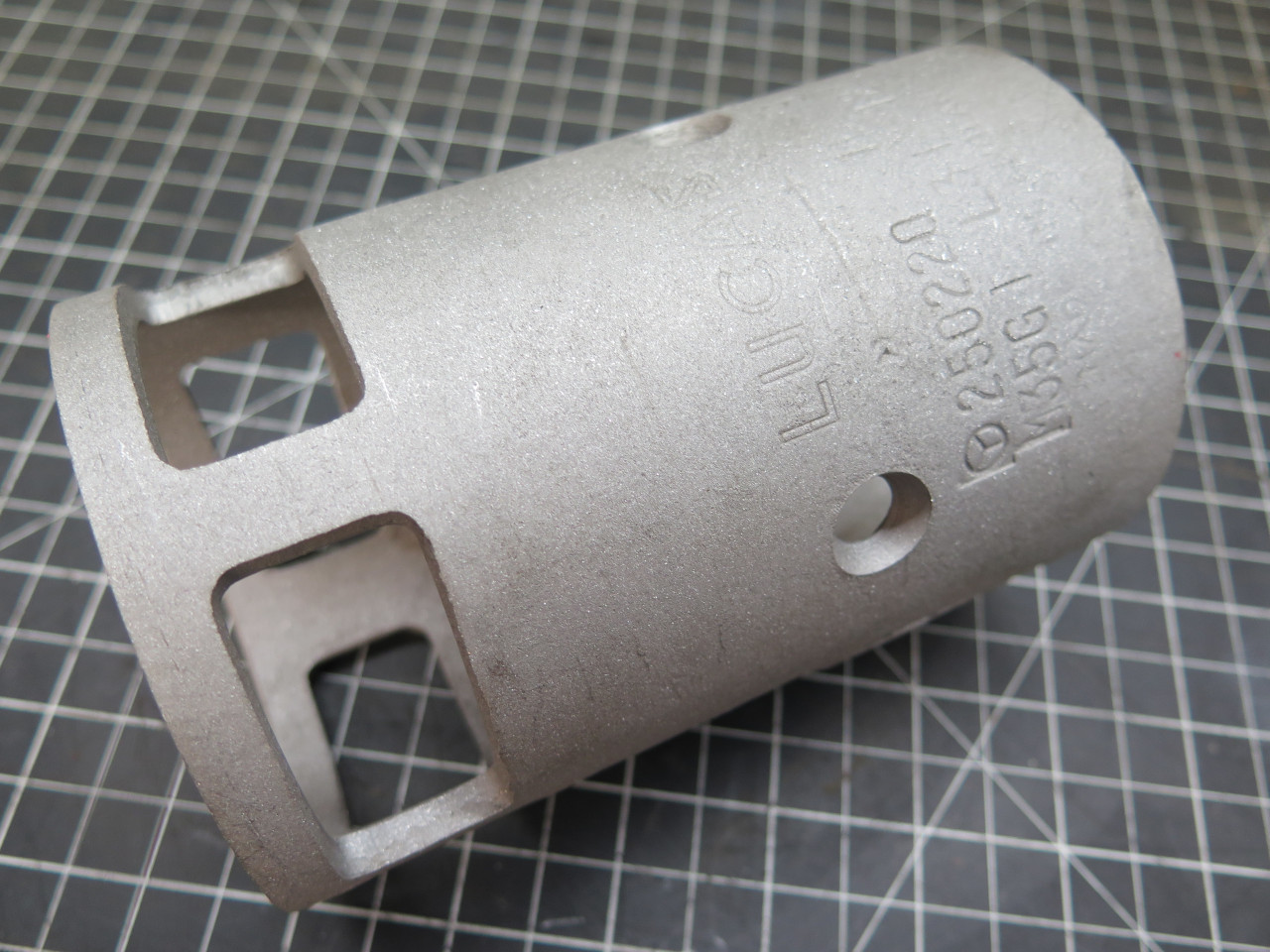
Lucas made starter motors for a wide range of vehicles and other
equipment. The motor in my car was an M35 type, with the "35"
signifying a 3.5 inch outside diameter of the motor casing. This
starter family, with its variants, was used in many British sports cars
of the era.
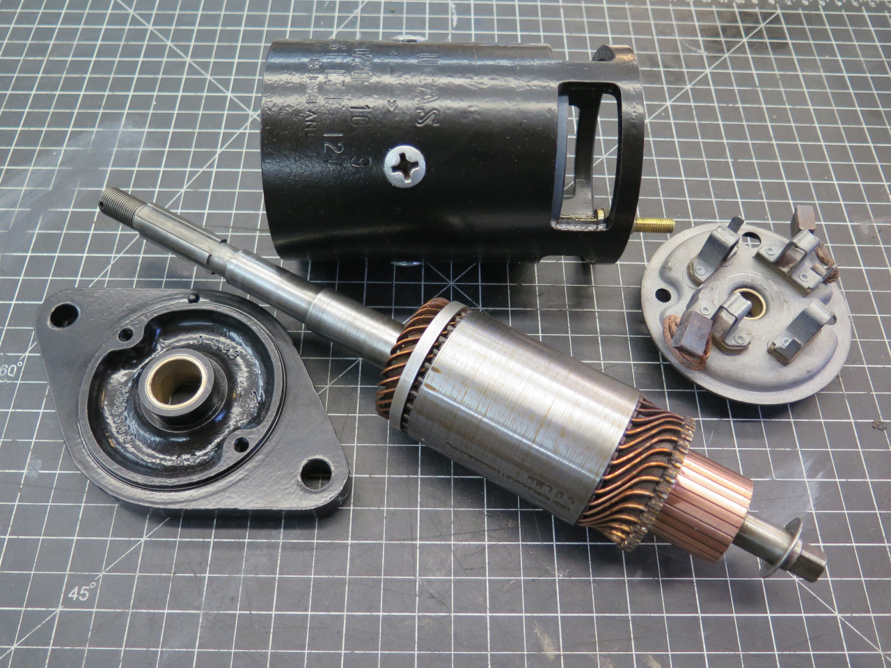
My starter was pretty crusty. With a date code of 10/59, it apparently wasn't original, but an early replacement.
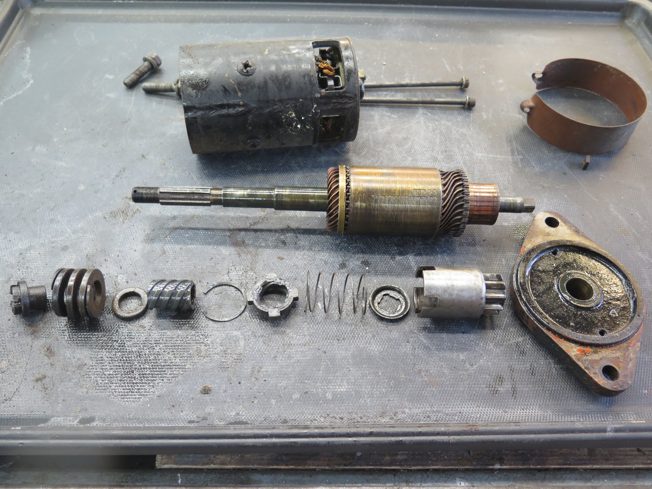
It was pretty quick and easy to get the armature free, with the hardest part being the inertial drive pinion.
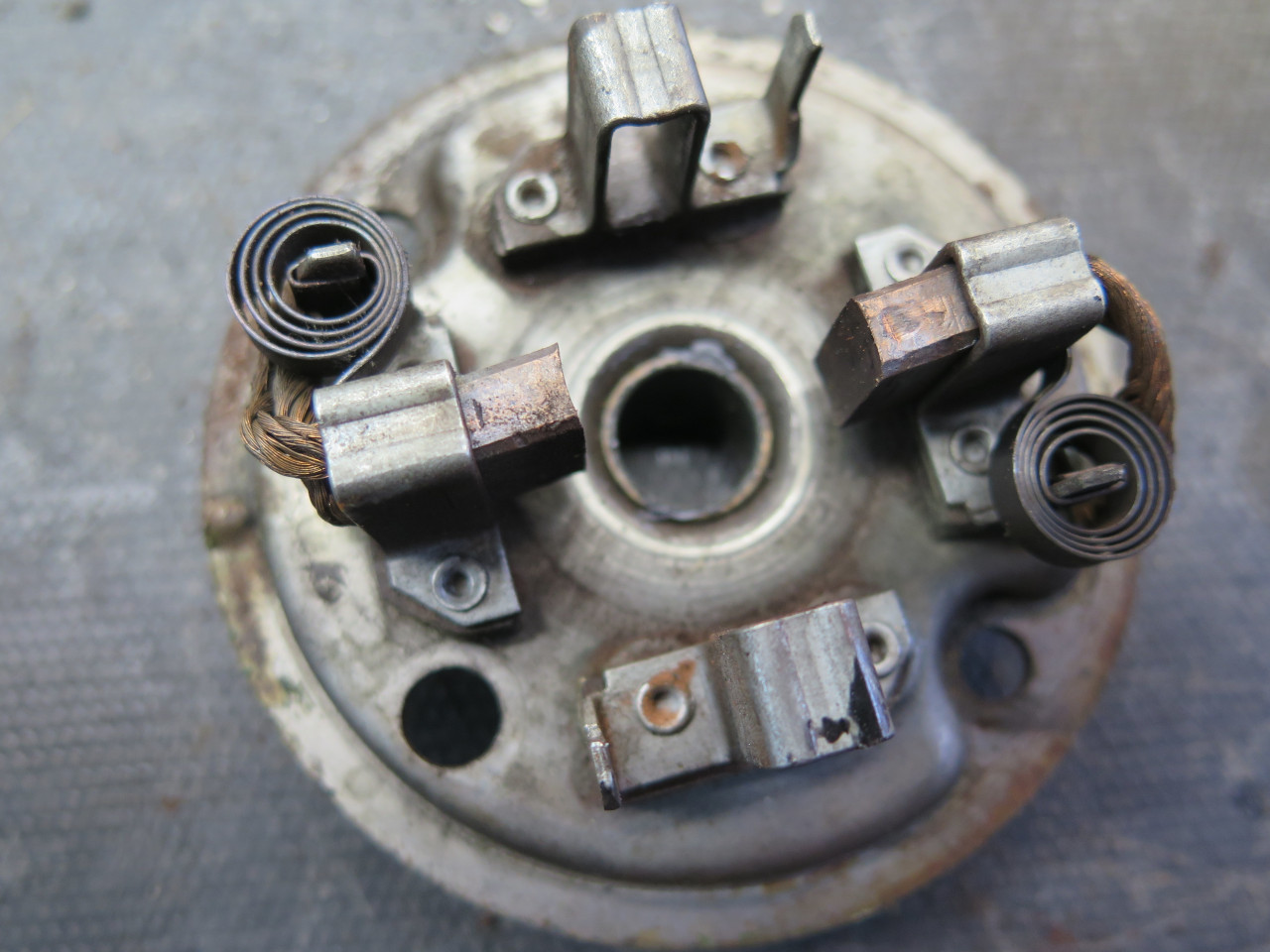
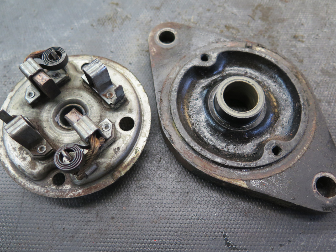
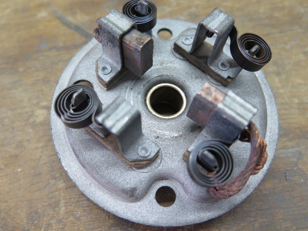
Then the brush assembly.
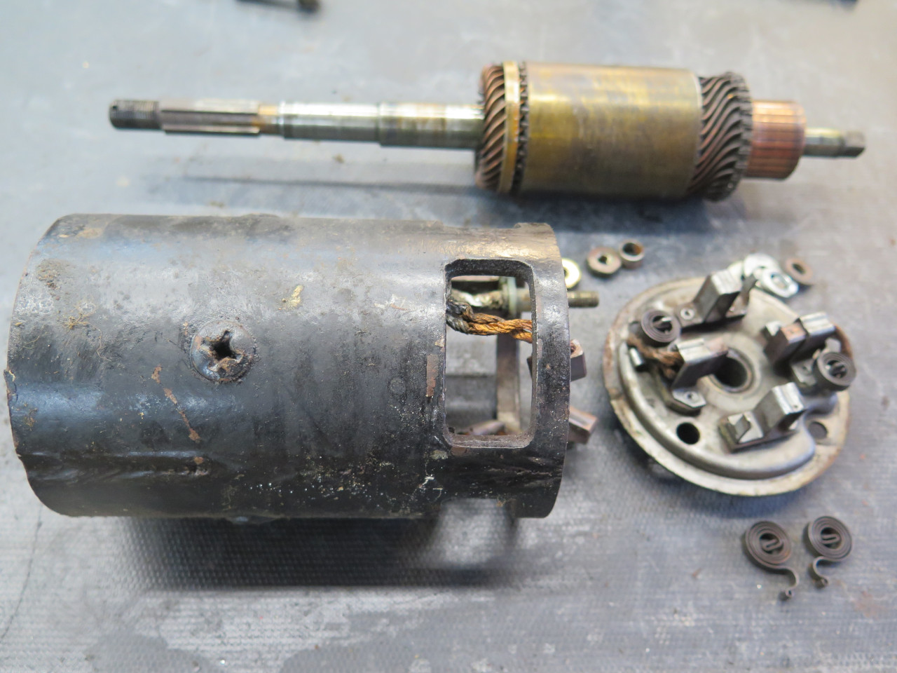
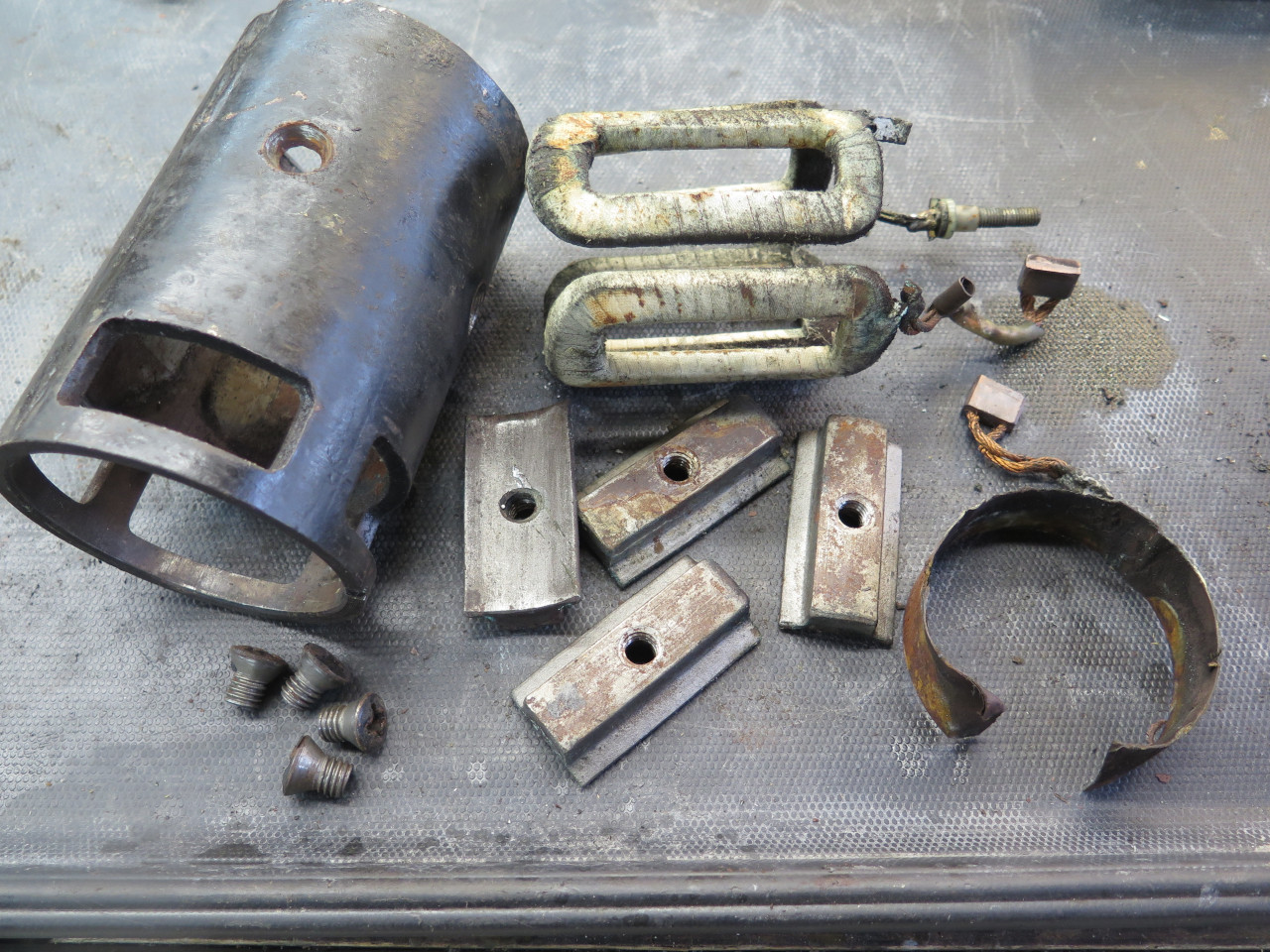
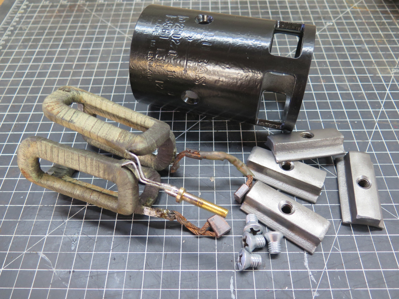
This left just the field coils in the motor case...
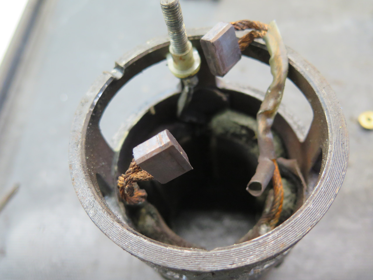
...which came out next, with their pole pieces. One of the brushes
fell off in the process. It couldn't have been a very good solder
joint.
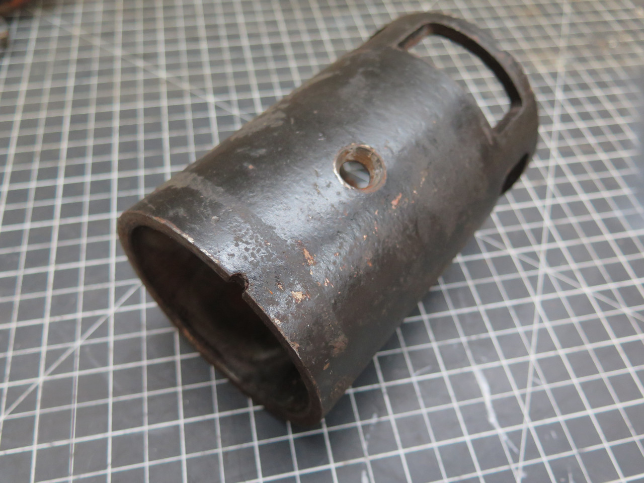
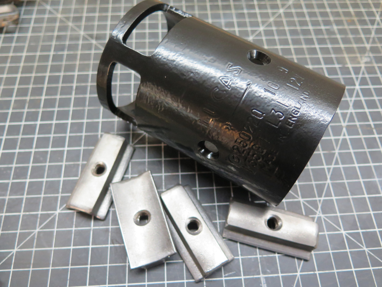
The motor barrel got a quick blast and a quick powder coat.
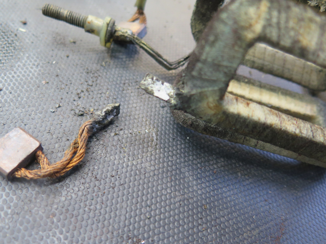
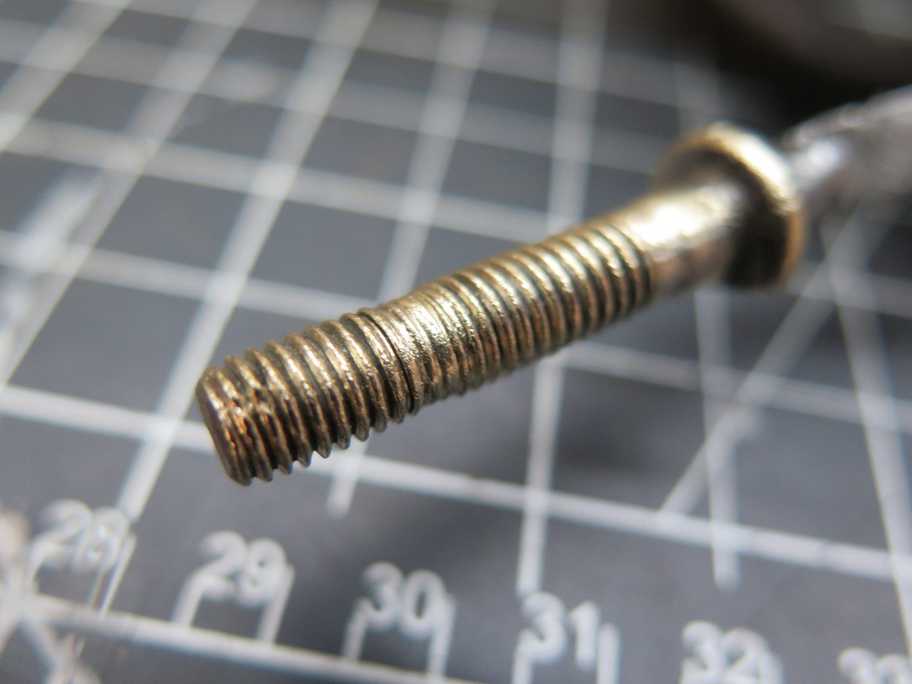
One thing I noticed during disassembly was that the brass electrical
terminal post, which is connected to the field coil assembly, had some
stripped or nearly stripped threads.
It seemed like a good time to fix that. I first unsoldered the
terminal from the field conductors. The field conductors are flat
strips of aluminum.
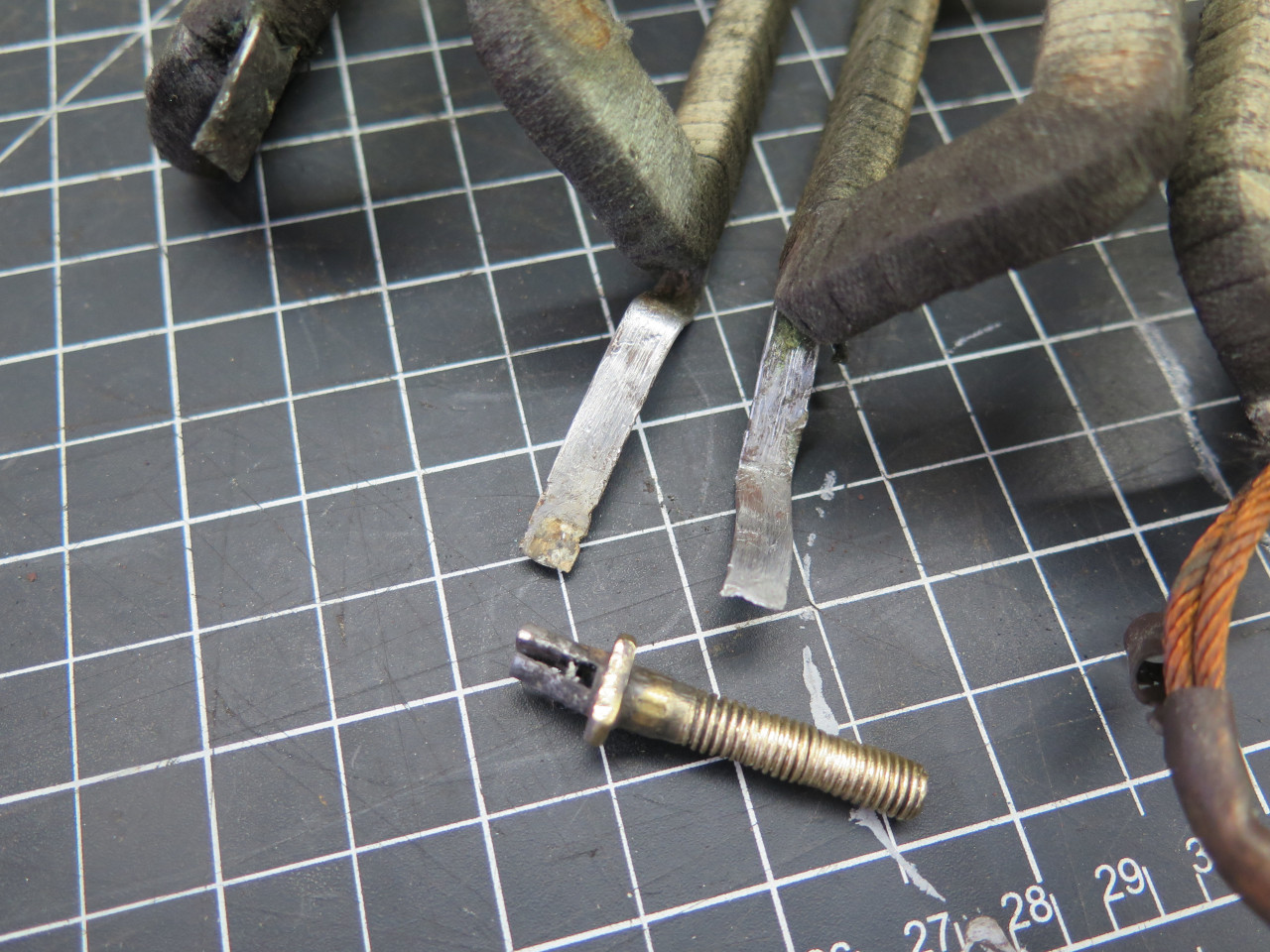
Found a little scrap of brass, and made a new post. I made two,
actually. On the first one, a worn out 1/4-28 die didn't make very
good threads.

Soldered it back to the field conductors, and also re-soldered the
errant brush wire. Soldering copper or brass to aluminum takes a
special solder.
Field assembly was then ready to go back home.
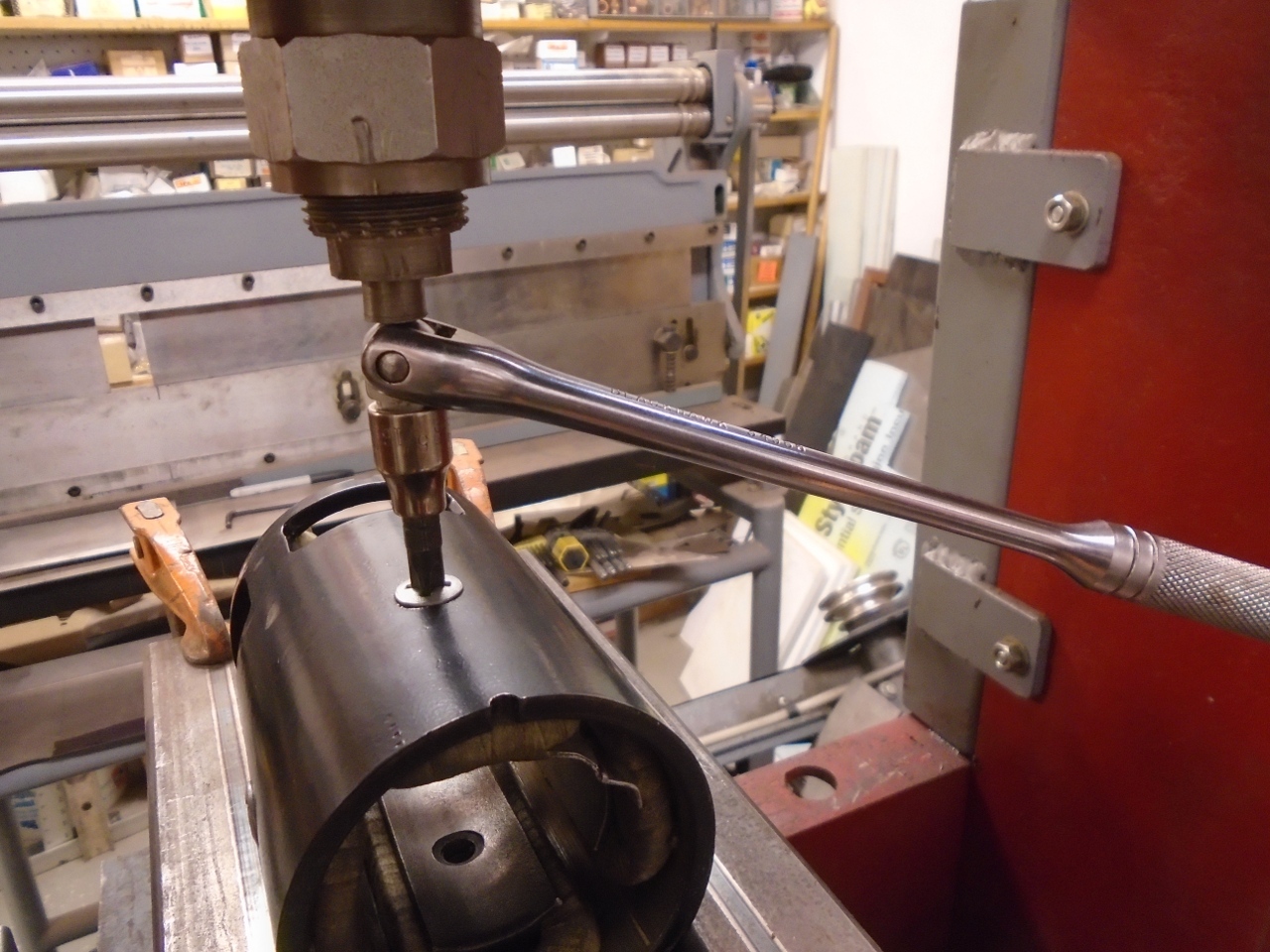
Those chunky screws that hold the pole pieces take a little extra
trickery to get tight enough. Same method was used to loosen
them. That's a hydraulic press pushing down on the driver.
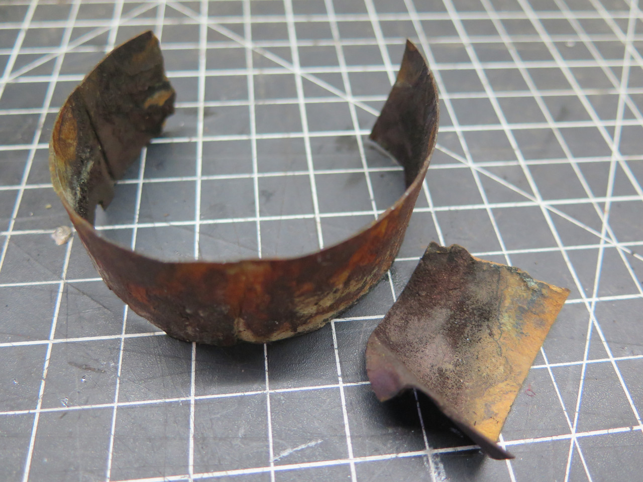
Some of the bare electrical connections are fairly close to the motor
case, so there was some insulating material wrapped around the ID of the
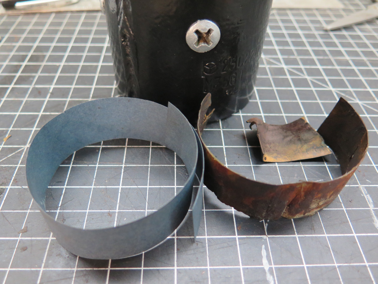
barrel. It was pretty far gone, and needed to be replaced. I
used some "Fish Paper"--a vulcanized paper product that is made and
sold for this kind of thing. It is commonly used in motors and
transformers. It was apparently as original to have the insulation
slightly encroach on the access openings.
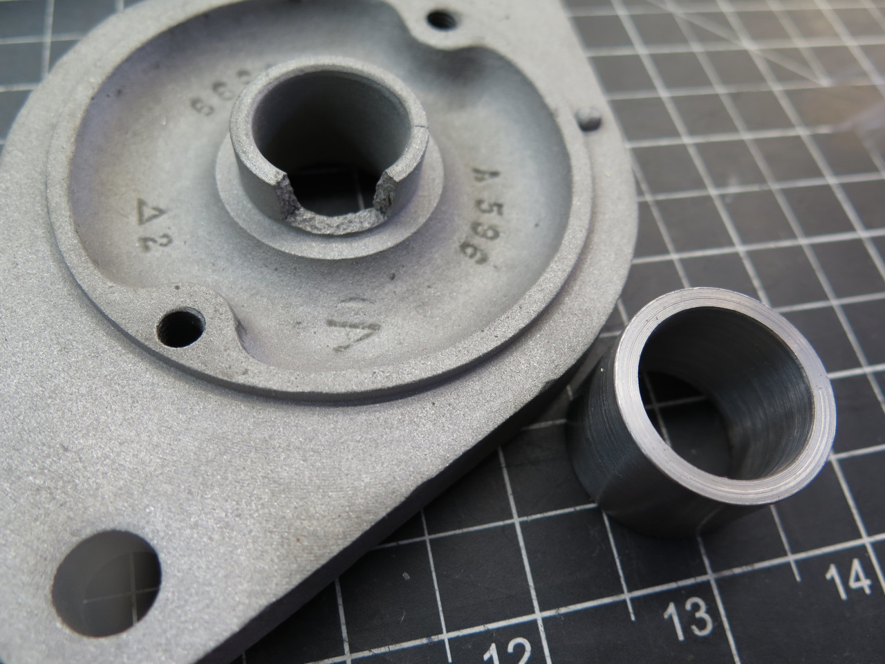
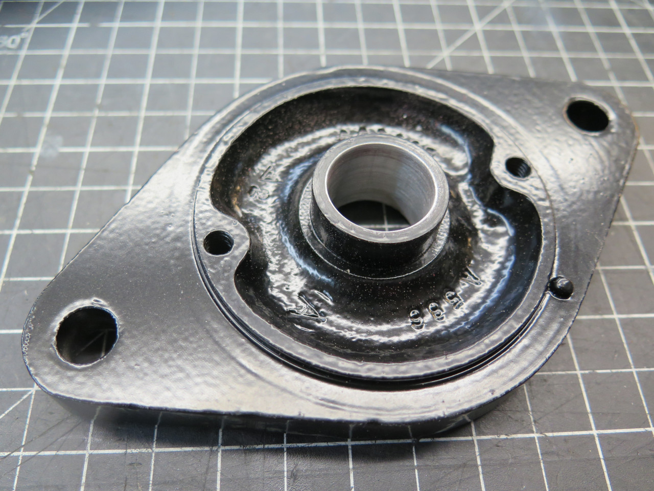
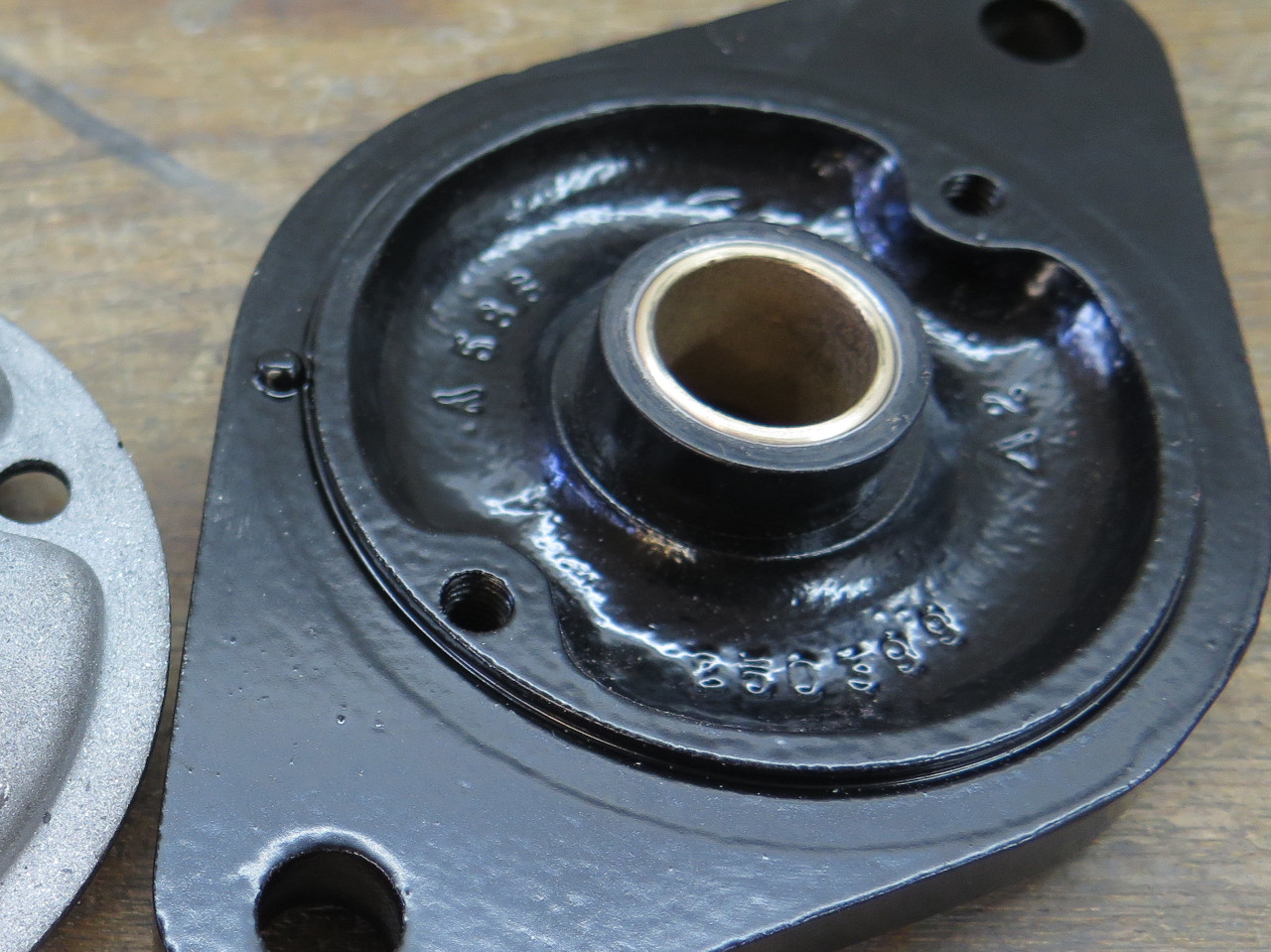
Next up was the end plates and their armature bushings. Both
bushings seemed a little loose to me, so I resolved to replace them.
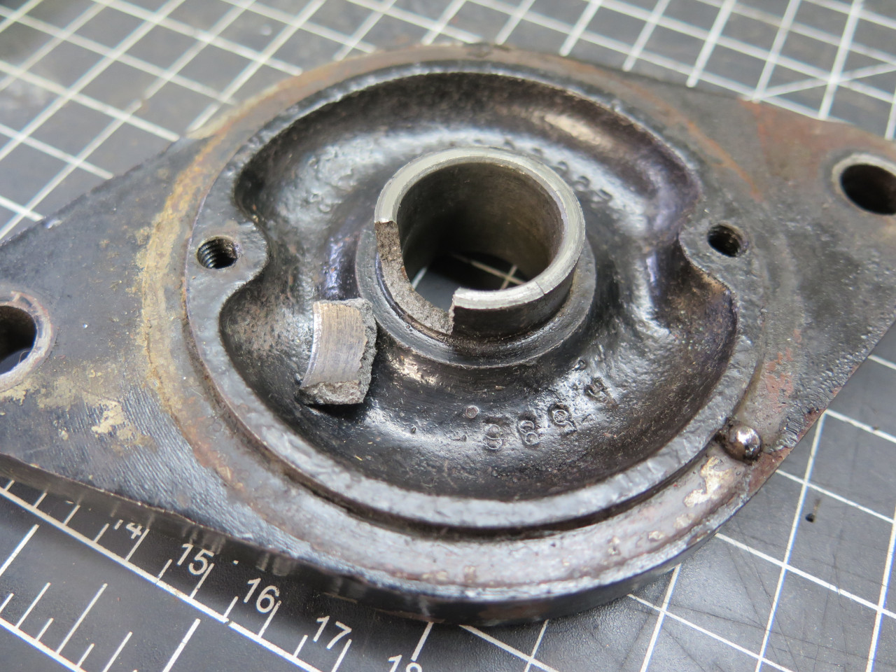
This is where tragedy struck. The pinion end bushing is a thinwall
part--it's only 1/32" thick. So making a drift to push it out can
be a little tricky. Tricky enough in fact that the one I made was
apparently a little oversized, and in my zeal to have that bushing out,
I overdid it and broke the casting.
When the adult language was done, I stepped back to assess. What
to do? Do I soldier on, pretending it didn't happen? Do I
scrap the starter? Those both seemed a little wimpy. Almost
cowardly. I finally decided to implement whatever heroic measures
it would take to fix my stupid mistake.
I blasted the cap clean, and got a chunk of heavy walled tubing...
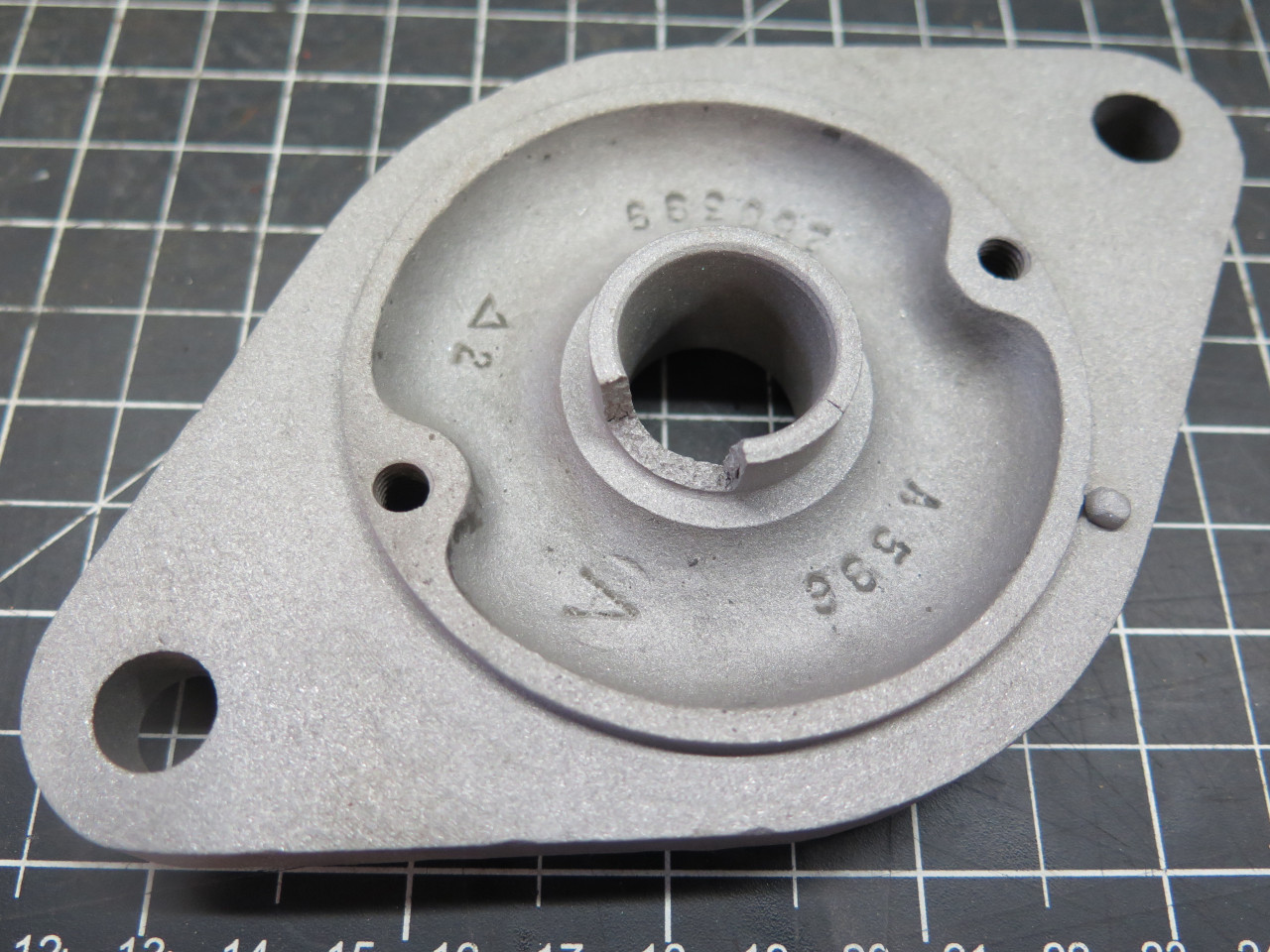

...and made an insert to replace the broken nose. I actually made
it slightly bigger than the original nose, so I could use a standard
bush with 1/16" wall thickness.
Then bored out the hole in the cap for a firm fit on the insert.
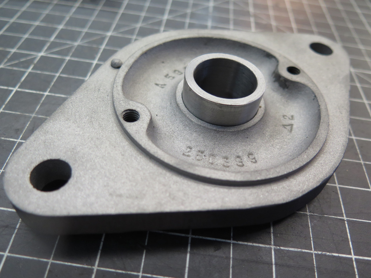
The insert was a nice fit, but a little insurance seemed appropriate. I added a few little fusion tacks just to make sure.
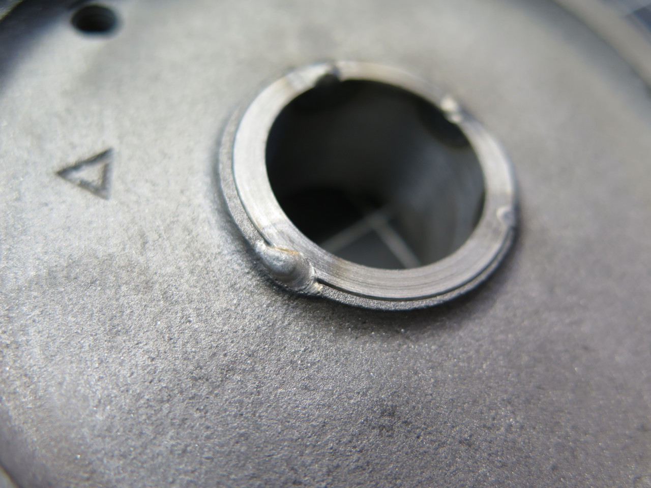
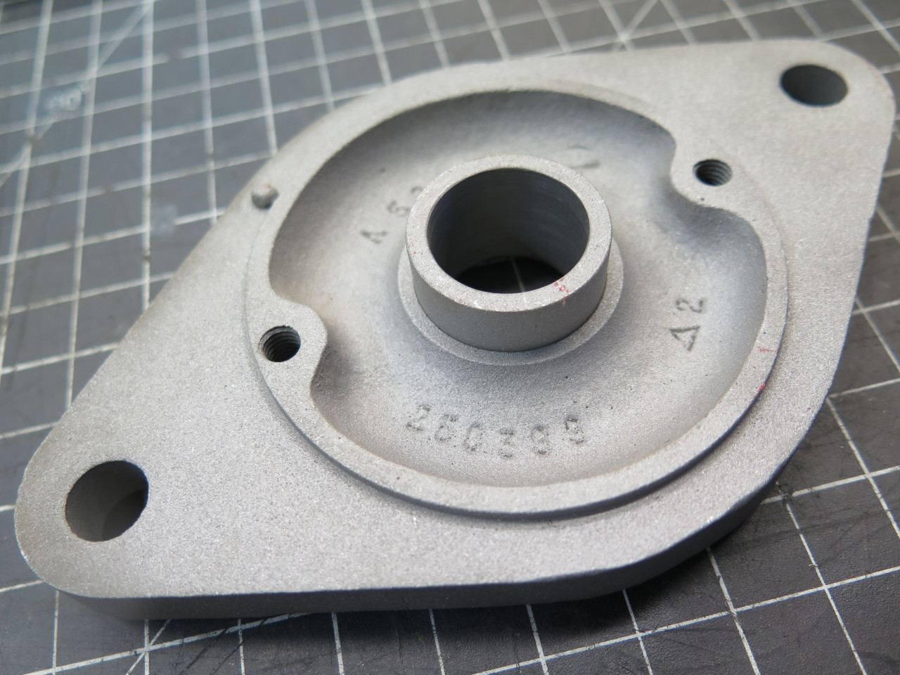
Blasted again to even everything out, blew on a tasteful powder coat, and pressed in the beefier bushing. Crisis resolved.
The bush for the brush end was also not without a little drama.
Pressing the new bush took a little more pressure than I liked, but it
did go home. However, when I tried to put it over the armature
shaft, it was hesitant. When it finally went on, it was very
tight. Something was wrong. I pulled the bush, damaging it
in the process. Luckily, I'd bought two bushes, so I measured the
second one carefully and compared it to the original bush and to the
bore.
The new bushes were right on spec, but the original bush and the bore
were slightly undersized. Rather than fret about the reasons, I
just skimmed a few thousandths off the OD of the second bush. It
went in fine, and fit the shaft fine. Go figure.
Ready for the final act.
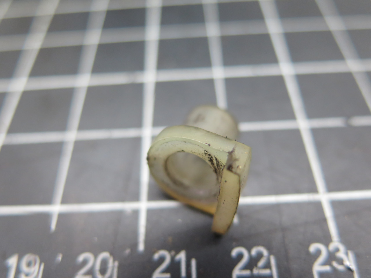
There's a little insulating sleeve that I had to hunt around for.
It keeps the power stud separated from the surrounding metal. It's
pretty important. Speaking of insulation, the ungrounded brush
wires had some sort of flexible insulating sleeve material, but some of
it had torn away. Since I couldn't fit a sleeve at that point, I
used some "self-amalgamating" silicone tape. It doesn't really
have an adhesive, but the material will meld with itself with a little
pressure.

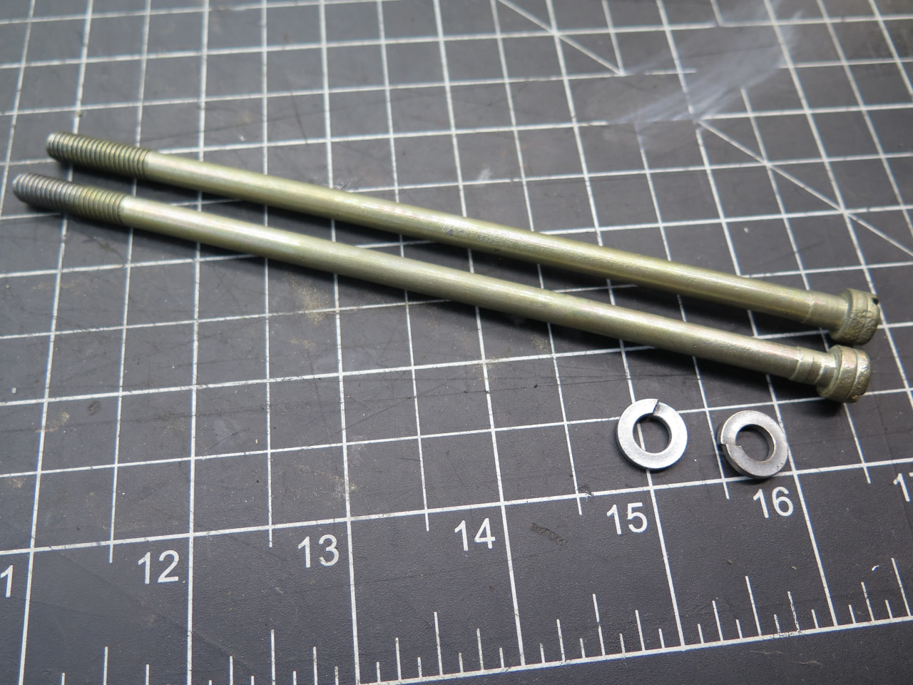
The end caps went on without much trouble. These long through-bolts keep everything together. I replated them.
I also discovered a little oddity about these bolts when I was chasing
the threads in the drive end cap to clean out some errant powder
coat. I was using the obvious 1/4-28 tap for this. It didn't
feel right. Sensing something amiss, I checked the threads on the
bolts. Sure enough, they are not 1/4-28, but 1/4-26. This
is a "British Standard Cycle" (BSC) thread, developed for British
motorcycles. All sizes of BSC threads 1/4" and larger are 26
threads per inch. Those Brits sure do love their odd-ball threads.
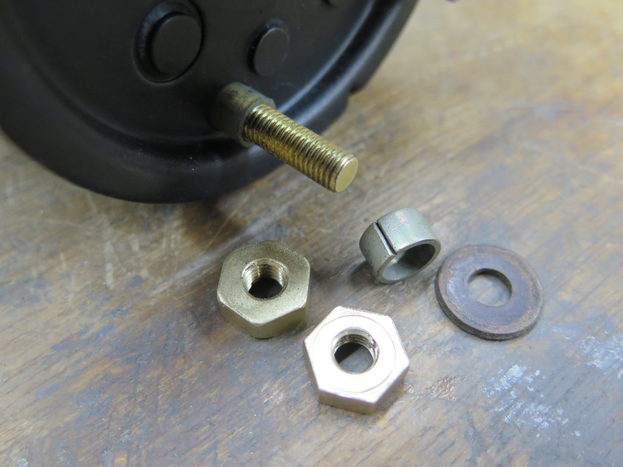
The electrical stud needs some care. There is a steel spacer, then
an insulating washer, then a nut to hold the stud in place, then
another nut to hold the eventual electrical cable in place. As is
common with high current electrical fasteners, these two nuts are
oversized, and made of brass. One of the nuts on this starter was in
terrible shape, looking like someone had repeatedly used a pipe wrench
on it.
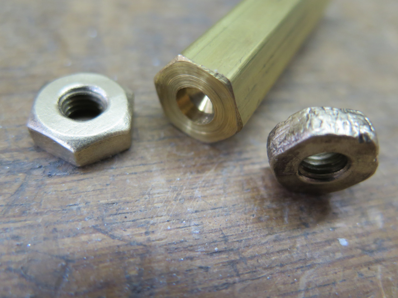
I'm sure these nuts can be bought, but they won't be a hardware store
item, and I didn't want to delay finishing this project for a silly
nut. And I had a little brass hex stock of the right size, so...
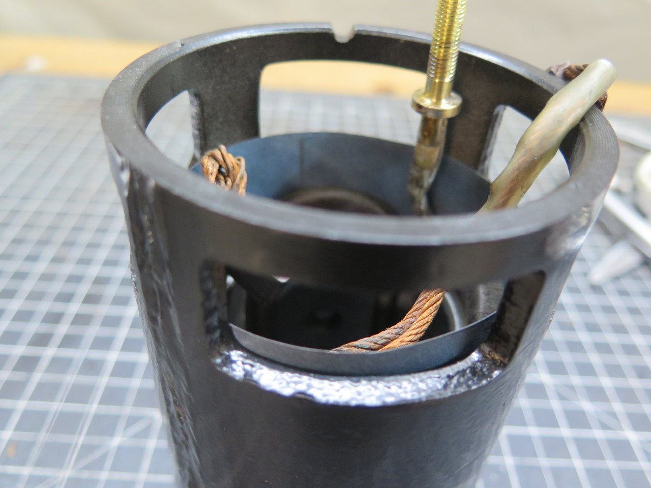
It was at about this point that the two ungrounded brushes were inserted
into their guides, and their respective springs moved into position. Then the band covering the access ports.
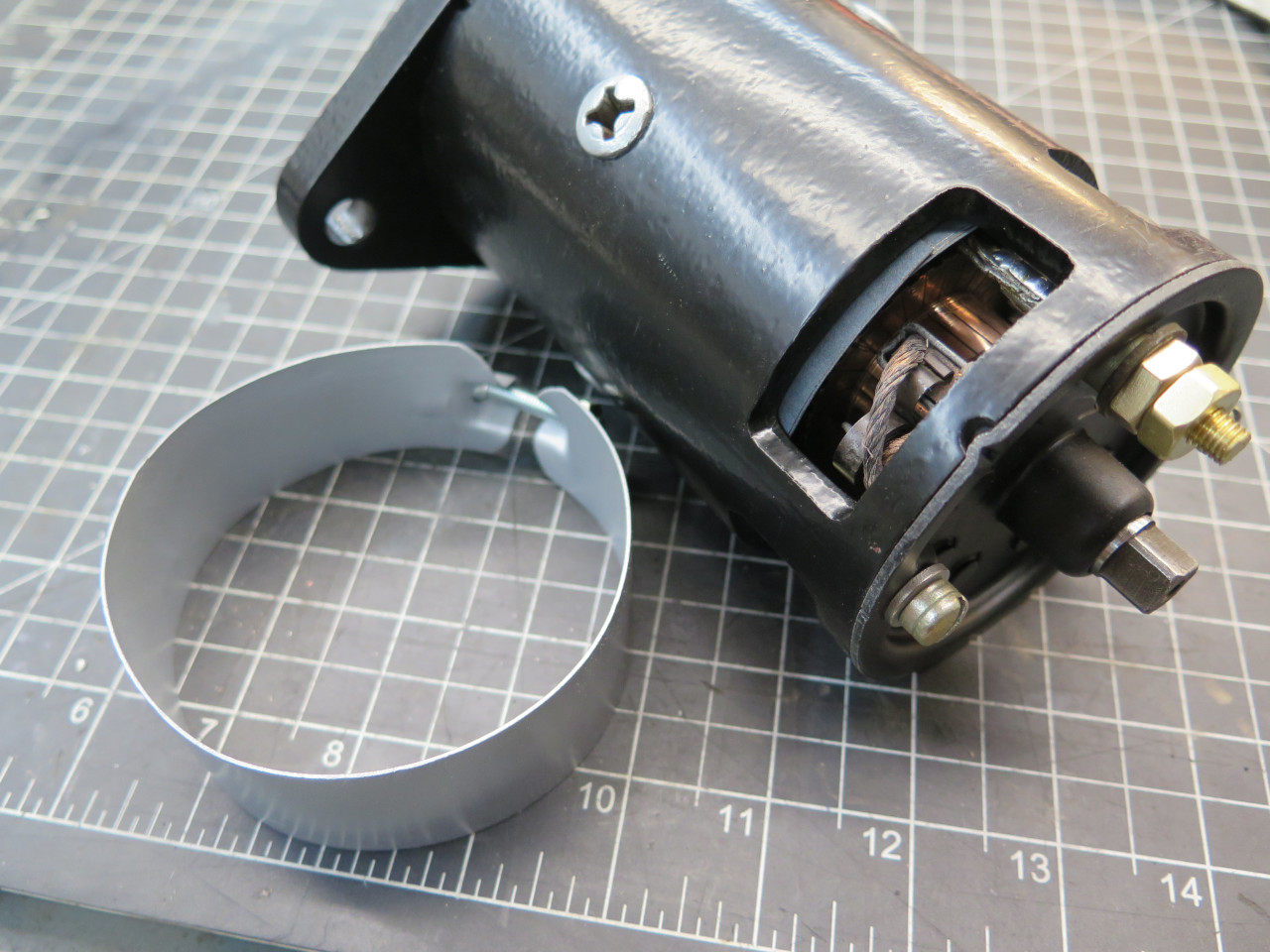
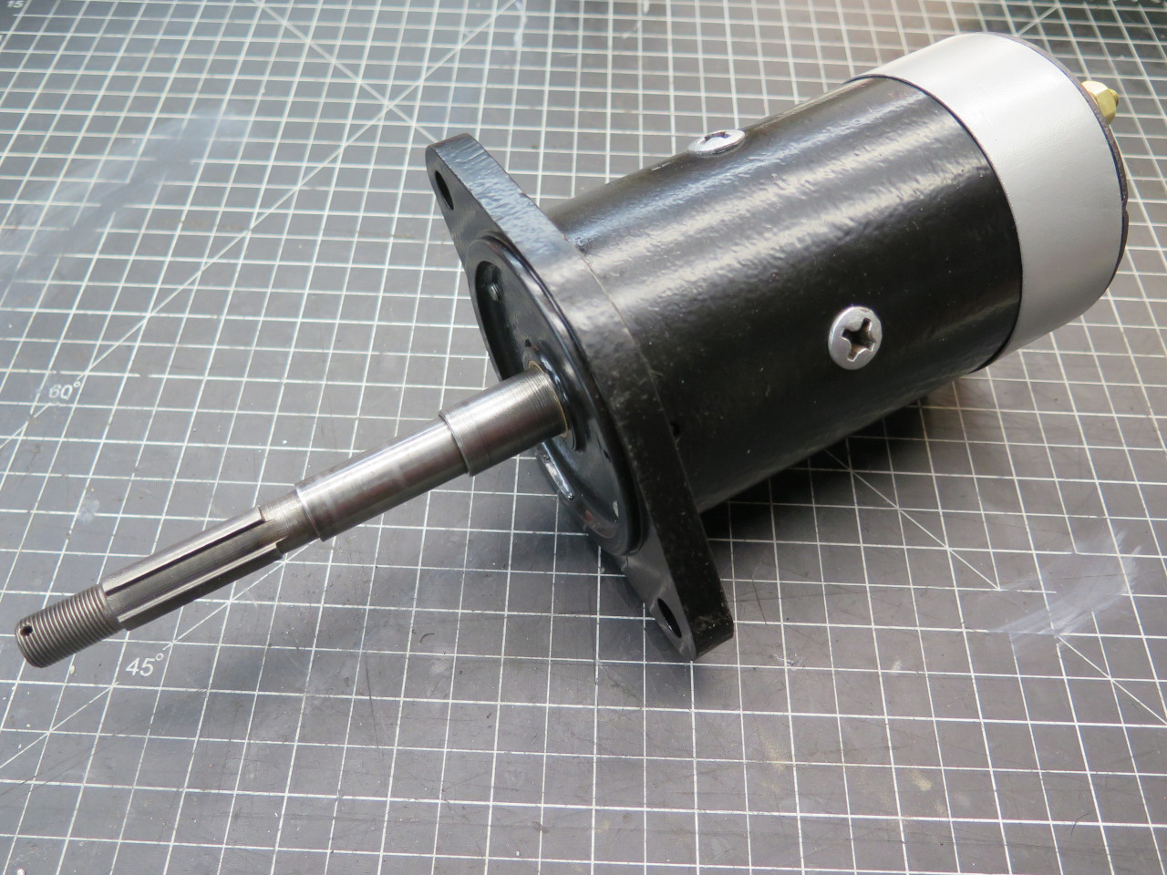
This completes the motor itself. Then on to the inertial drive mechanism.
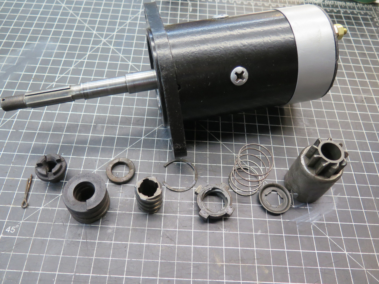
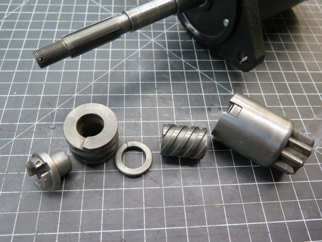
These parts form the pinion barrel. It's this barrel that slides toward the motor when the armature shaft begins to spin.
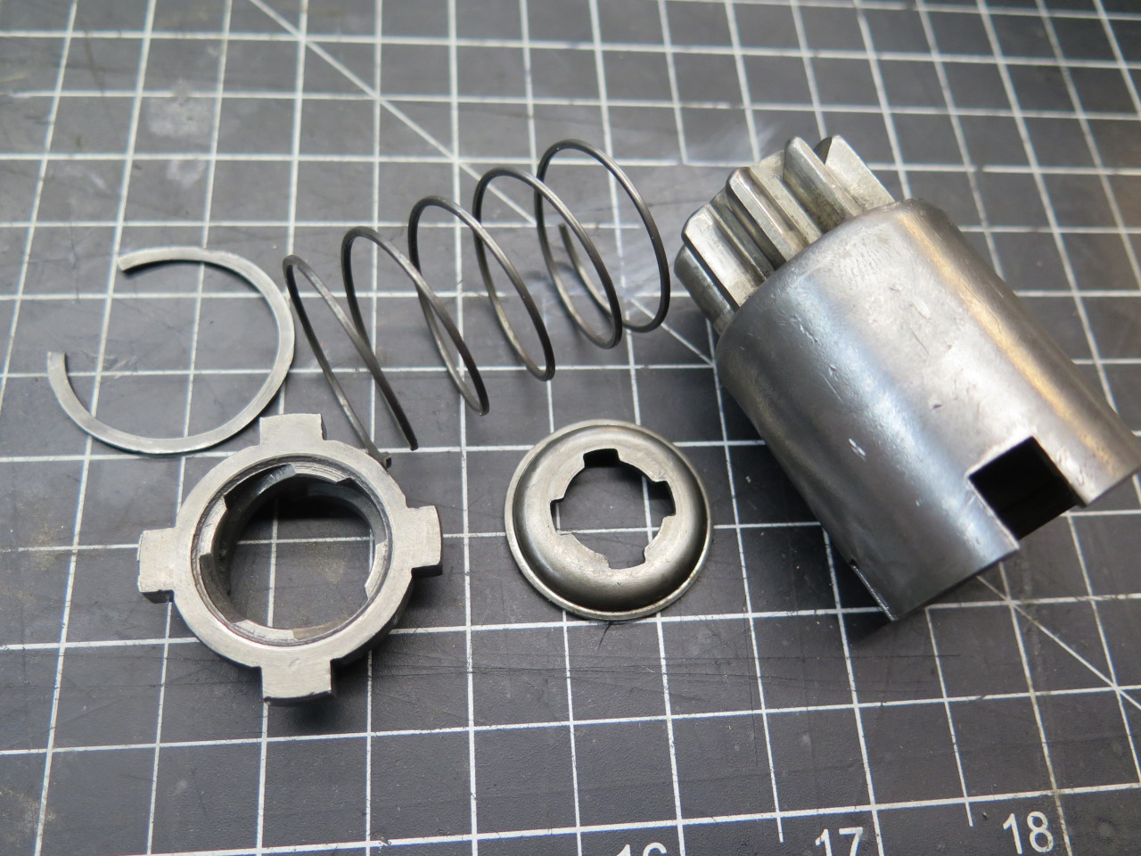
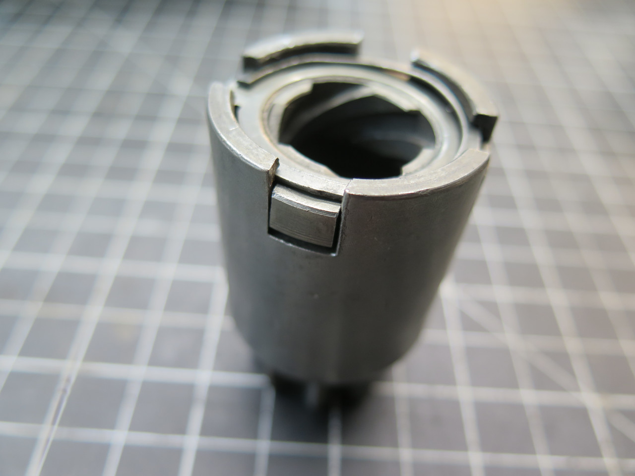
Then the rest of the drive parts. All of these parts were in really good shape.
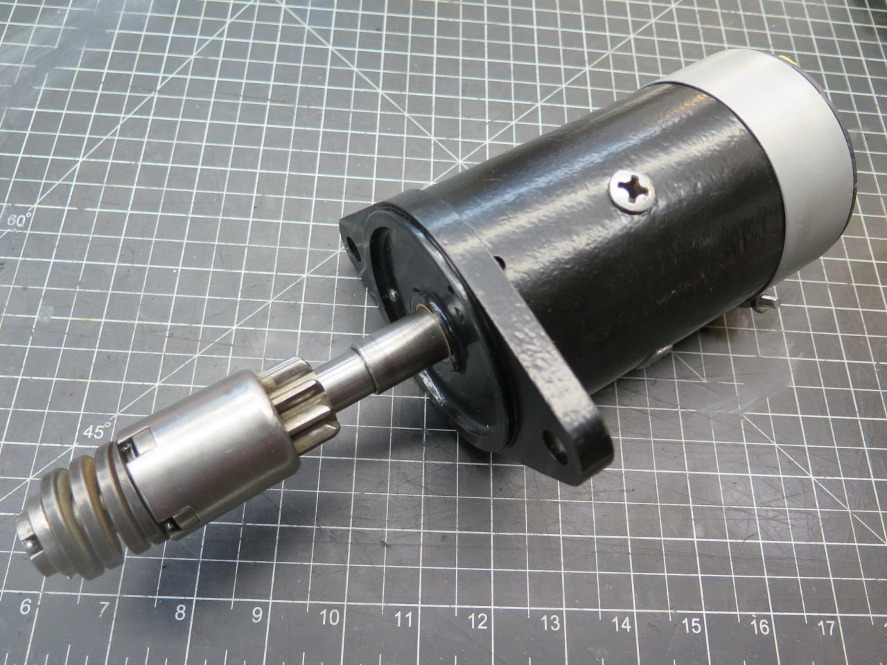
I don't have a power supply that's man enough to test this motor, but
the shaft turns, and there is something less than one ohm of resistance
between the stud and ground--both good signs. I'll try it with a
battery when the weather warms up.
This job would have been almost trivial without the ham-fisted mistakes
and the sidetracks. Cost was around $10 for the heavy tubing, but I
have most of it left.
Comments to Ed at elhollin1@yahoo.com.
To my other MGA pages.