To my other MGA pages
February 20, 2025
Wiper Motor
One of the niceties of the otherwise pretty spartan MGA was an electric
windscreen wiper system. Many British sports cars of the era used a
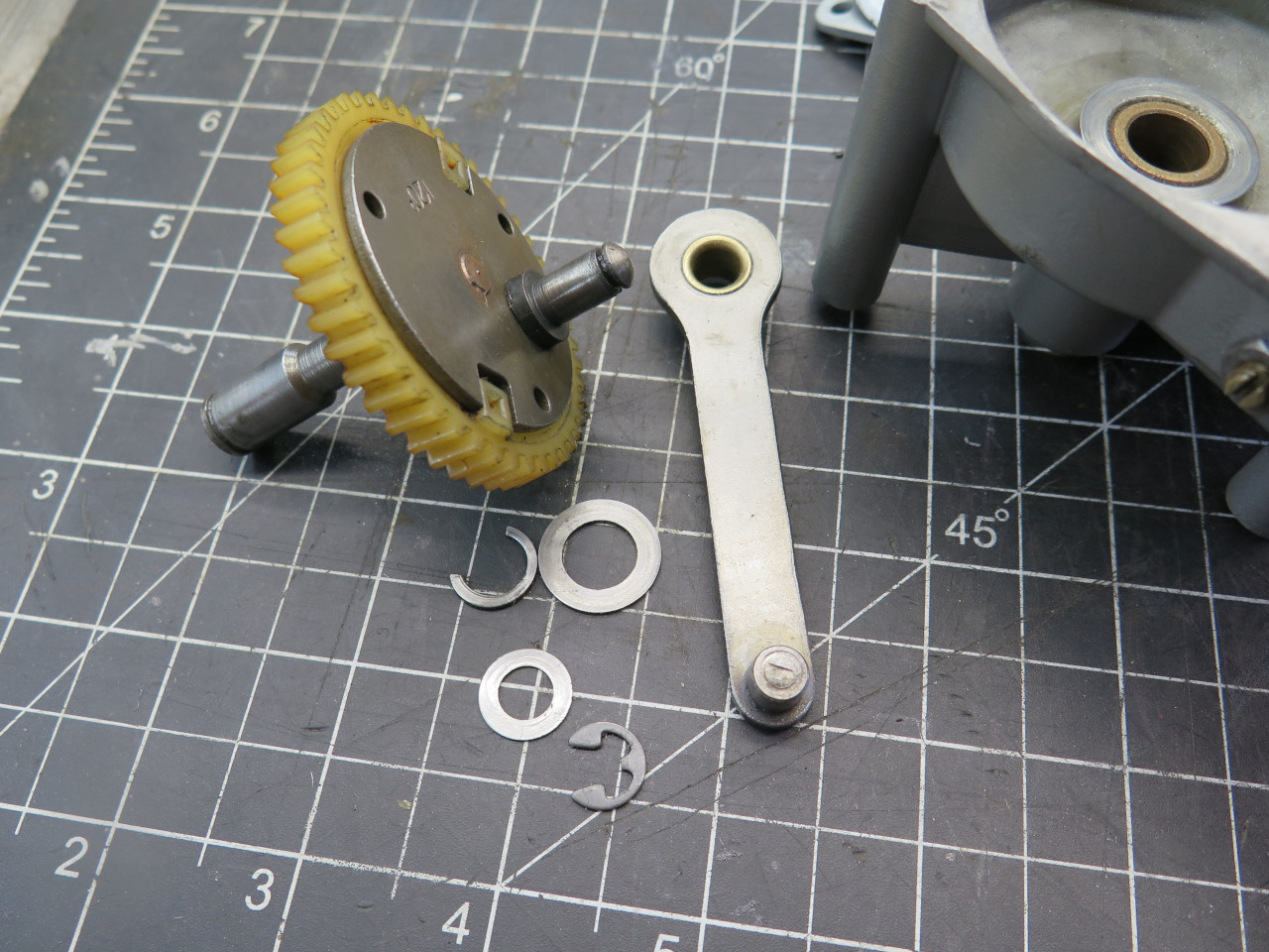
similar wiper arrangement. An electric motor turned a crank via a
worm gear. The crank pushed and pulled a toothed cable that
turned a toothed wheel in each of the two or three wiper bases.
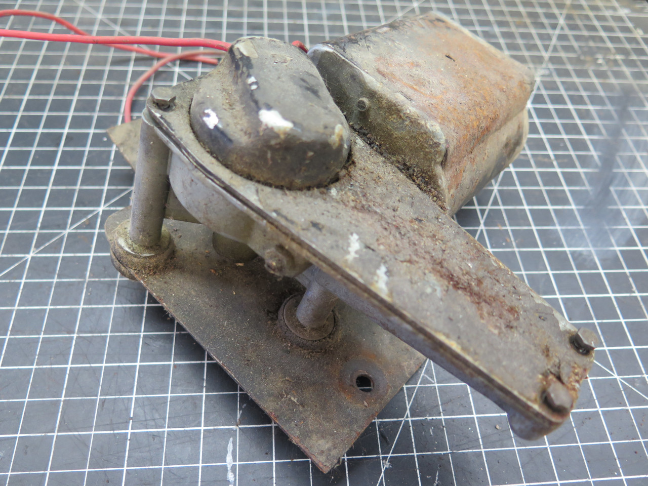
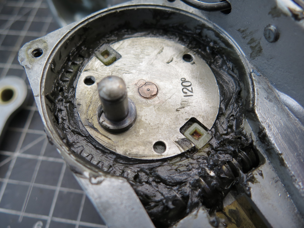
My motor was pretty grungy, but I tested it, and it actually ran!
At 12 volts, it drew around 2.7 amps, and at 14 volts, about 3.0.
According to a couple of sources, this is within the normal range.
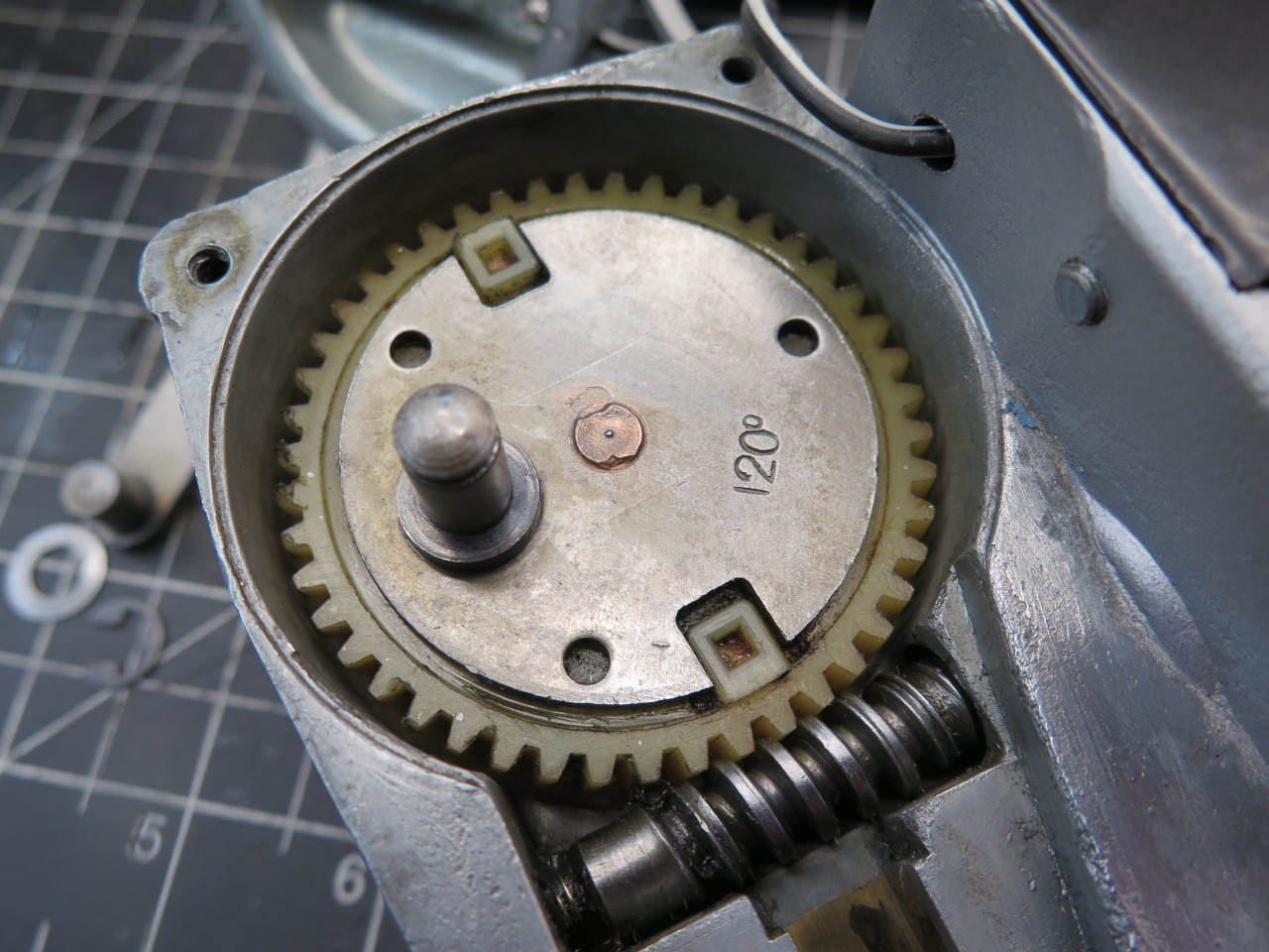
The inside of the gearbox looked a lot cleaner.
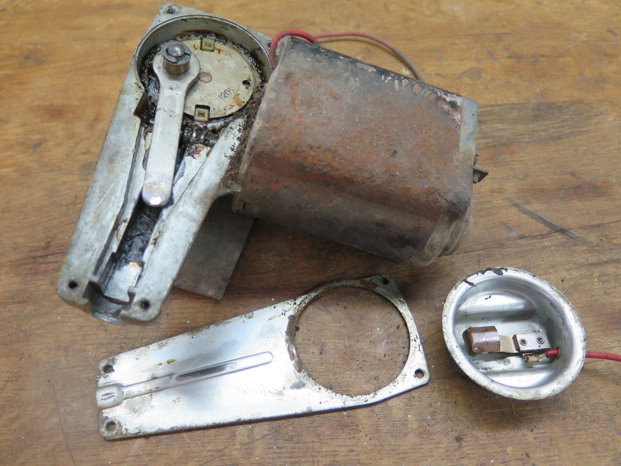
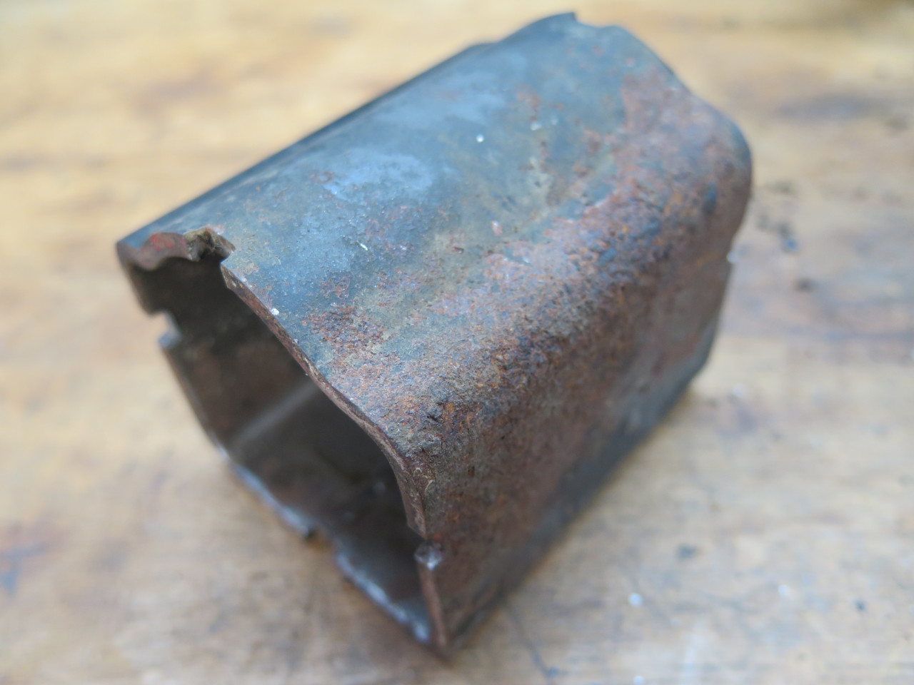
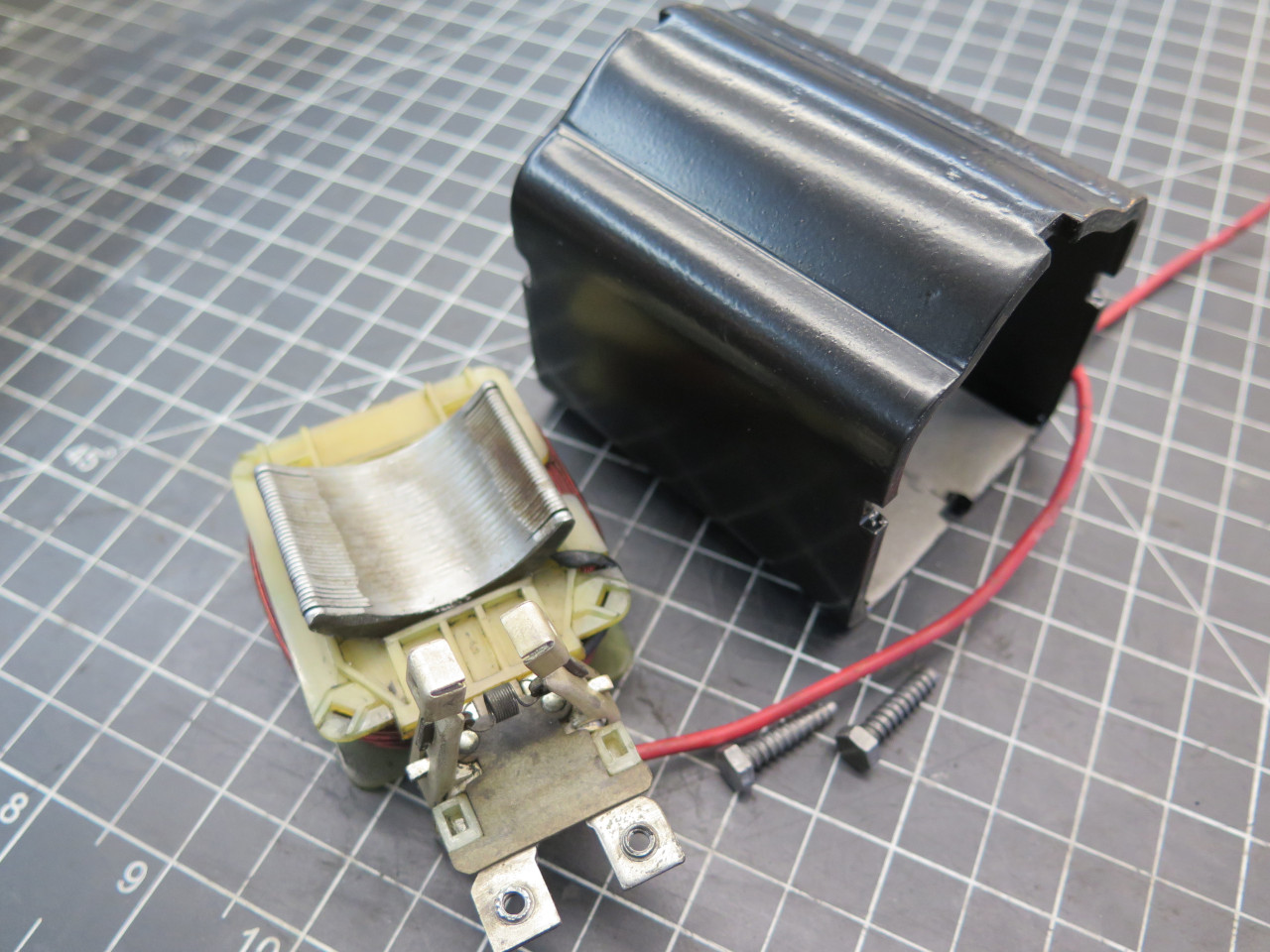
Disassembly was straightforward. The main motor housing was pretty
rusted on the top side, but a few minutes of blasting cleaned it right
up.
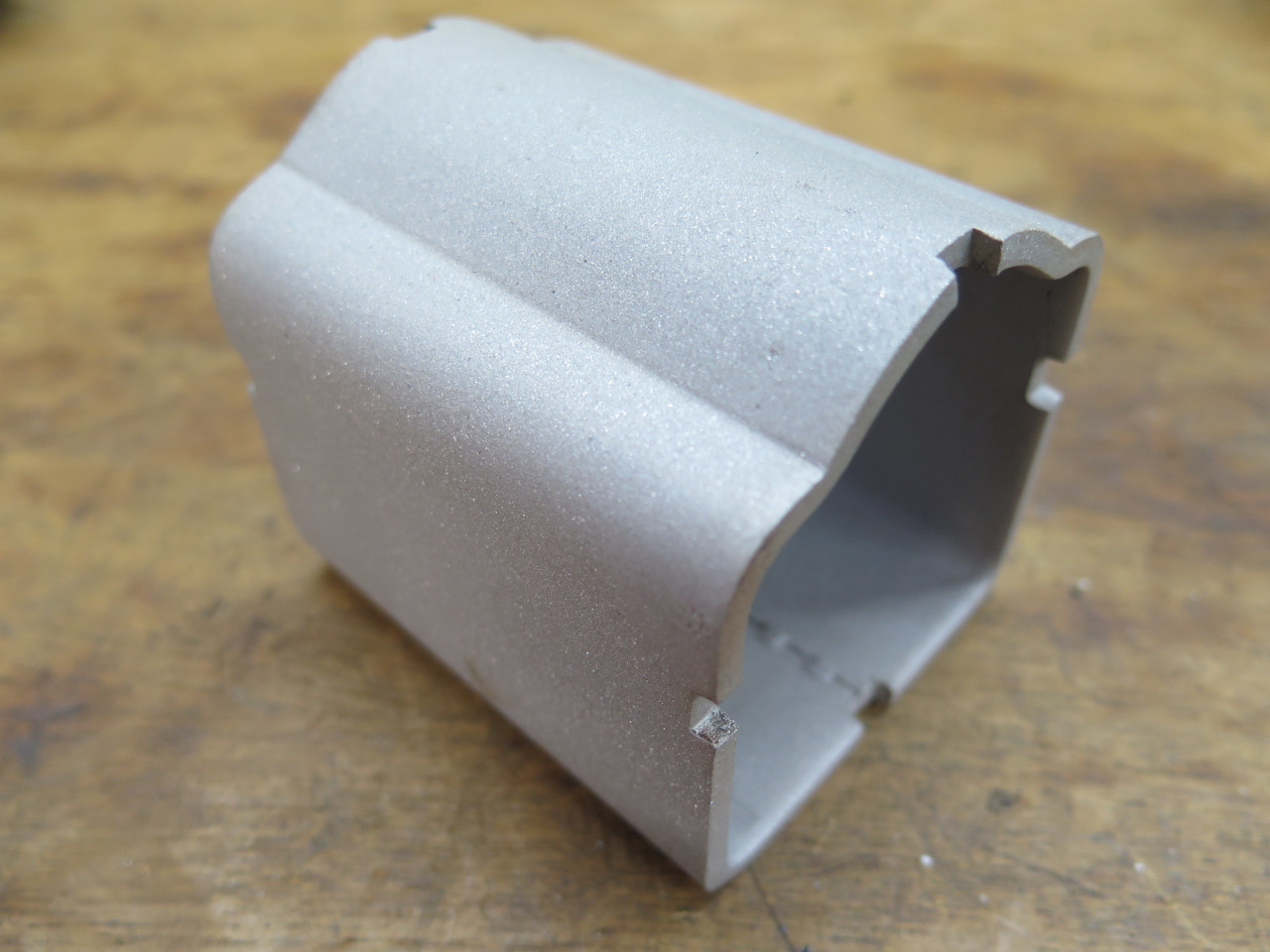
A quick powder coat made it look a lot better, but the rust pitting was obvious.
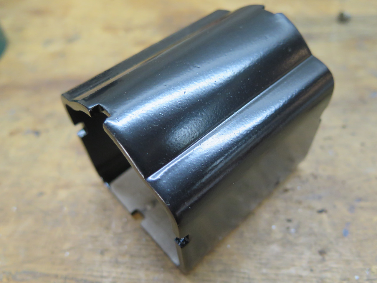
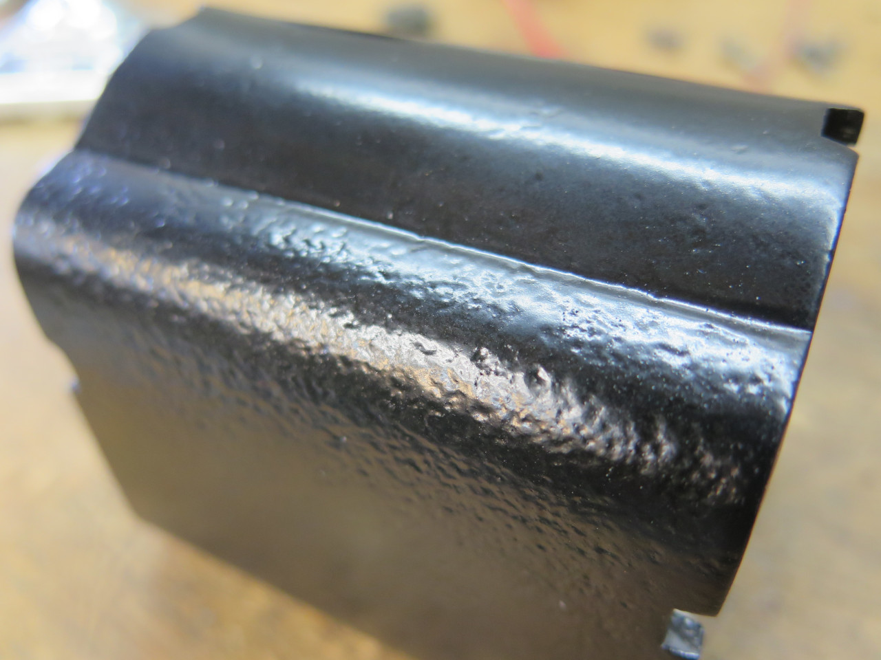
I wasn't happy with the rough surface, so I noodled it a bit.
"The piece looks symmetrical, so why couldn't you just flip it end for
end so the good side is on top?", I heard my Inner Engineer say in a low
voice.
"Hmmm, " I thought. "Looks like that could work."
In mulling it over though, I found a fly in the ointment. There
are two holes in the flat side of housing for fastening the field
winding/brush assembly. They looked to be intentionally biased
toward one end. Flipping the case would put the brushes in the
wrong place.
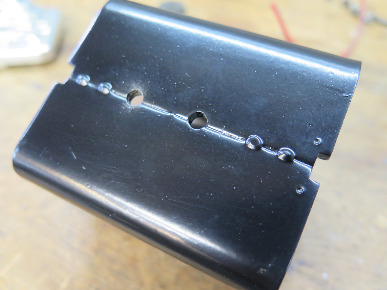
"So just drill new holes," I heard IE say, offhandedly.
"Right!" I said. "I guess I could do that."
The field/brush assembly seemed to like that just fine.
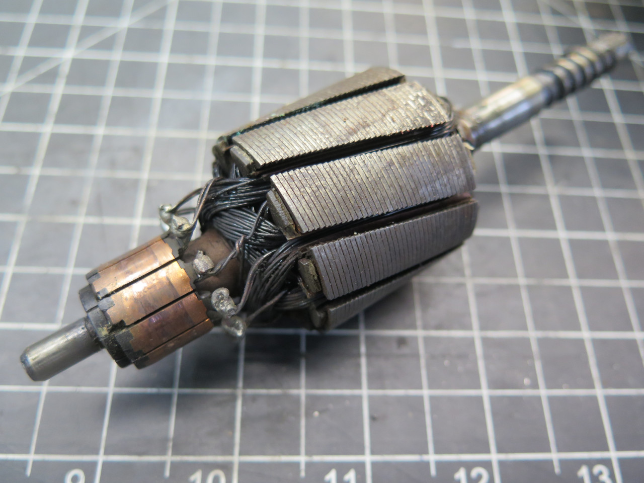
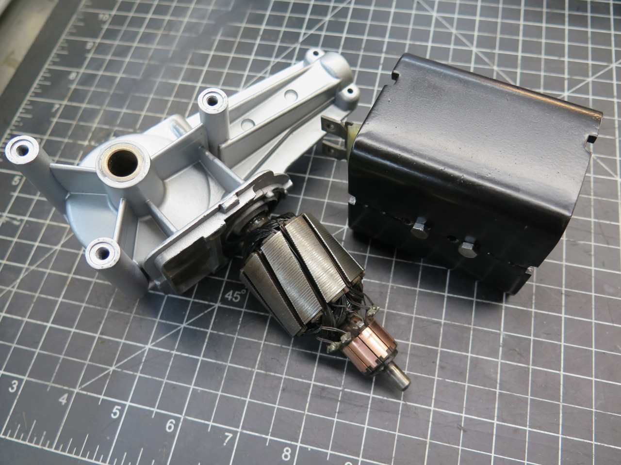
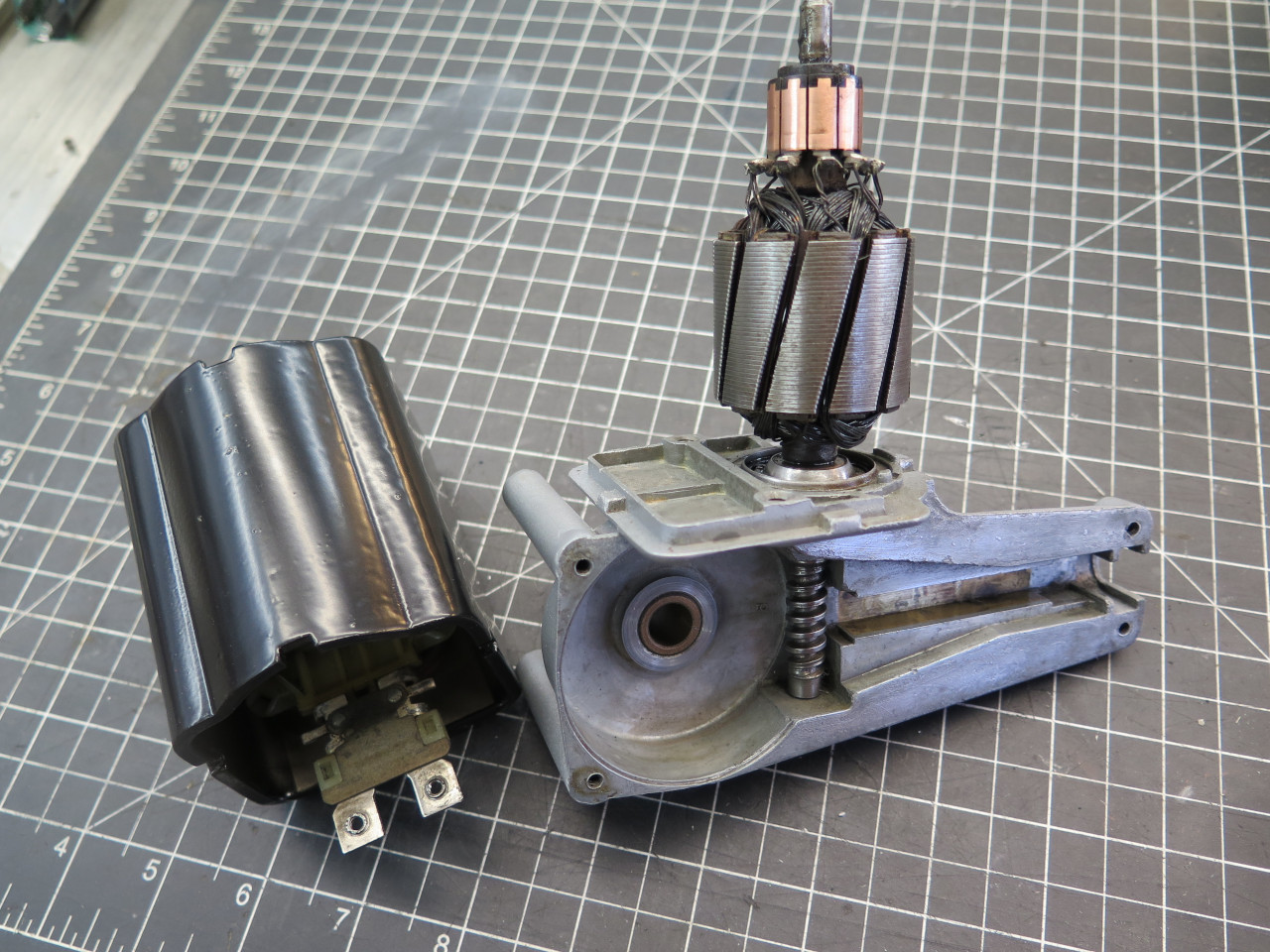
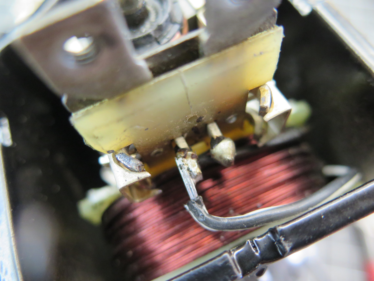
Then, the armature. I was a little disappointed that the windings
looked burnt to me. But the motor seemed to be running fine, so I
filed my observation and soldiered on. The commutator didn't take
much to clean it up.
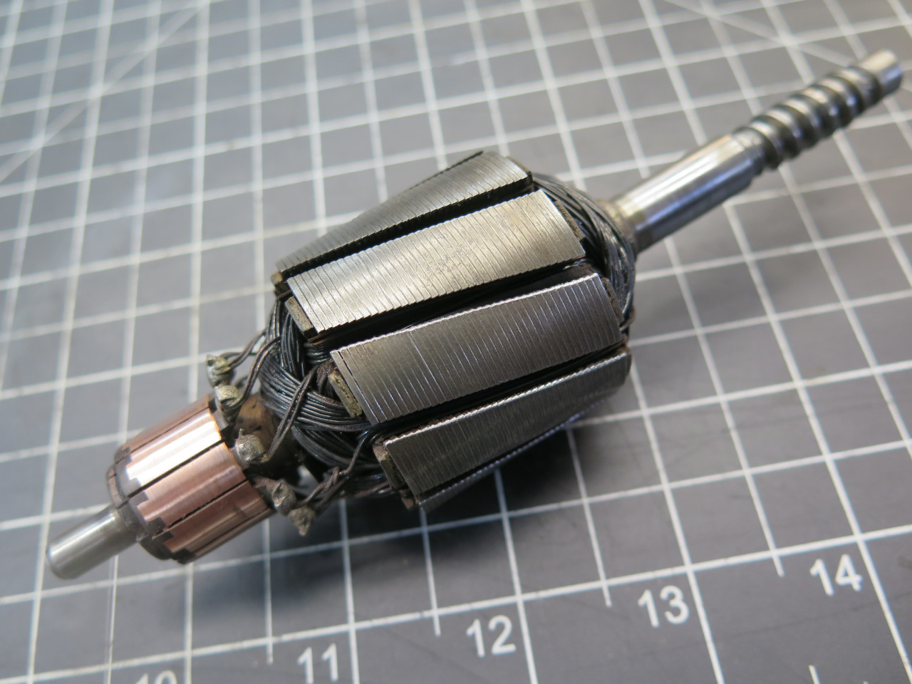
I then checked all of the bronze sleeve bushings--two for the armature,
and one for the main gear. They were all still a very nice fit,
and I couldn't see any reason to replace them. The armature
bushings aren't really practical to replace anyway.
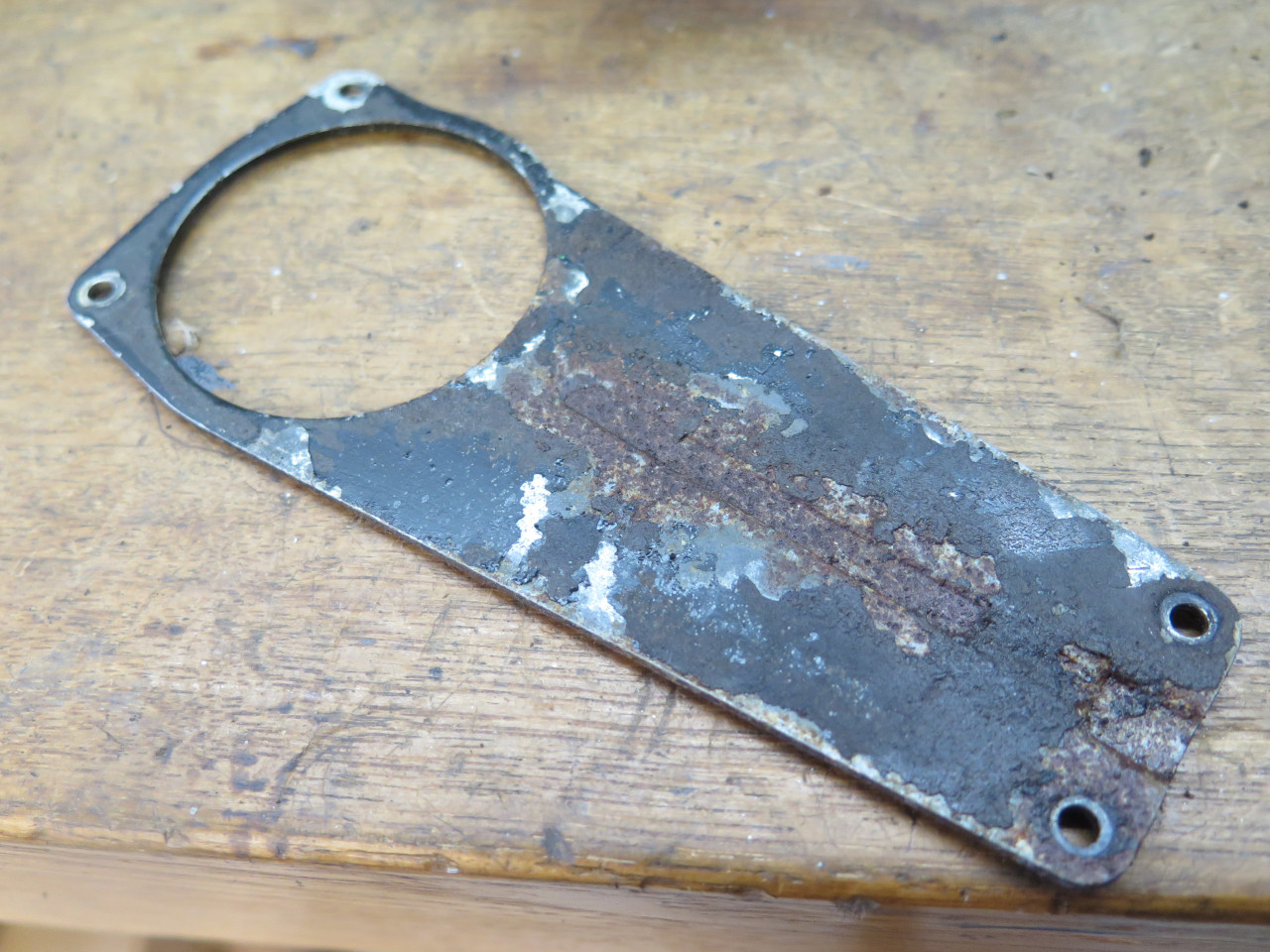
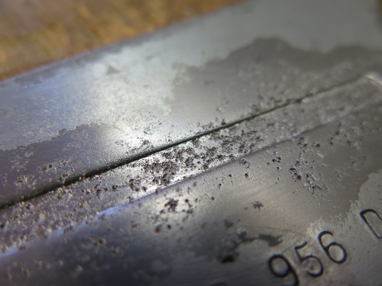
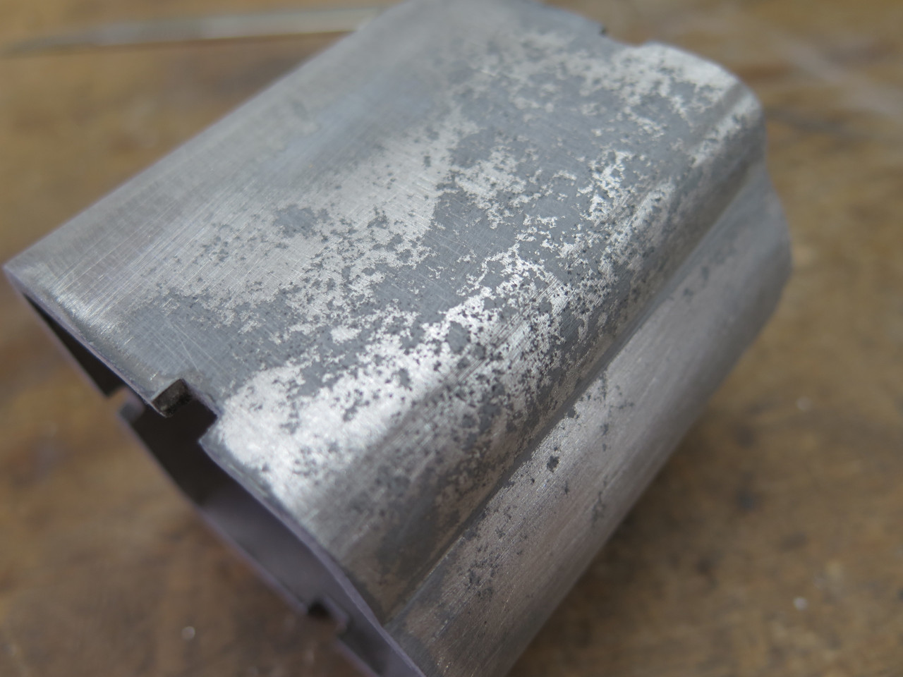
Another rust victim was the gearbox cover. I would normally
dissolve the rust with muriatic or phosphoric acid, but these both
attack zinc, and the cover had quite a bit of intact zinc plating,
especially on the inside. So I used a gentler chelate
treatment--Evaporust in this case. It eats the rust but not the
zinc. It's easy to see where the corrosion ate the zinc away and
pitted the steel.
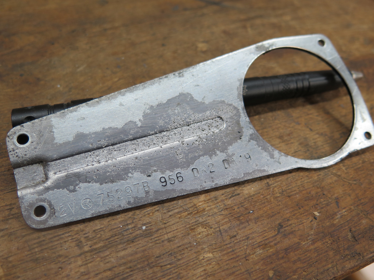
I really wanted to fill those pits, but since I planned to re-plate the
cover, the filler would have to be conductive. I tried solder,
using a solder paste and heat, but it was only partially
successful. Some of the pits would not accept the solder. I
assume there was still some contamination in the pits. This
irritates me, and if it continues to bother me, I may come back to it
for more drastic measures.
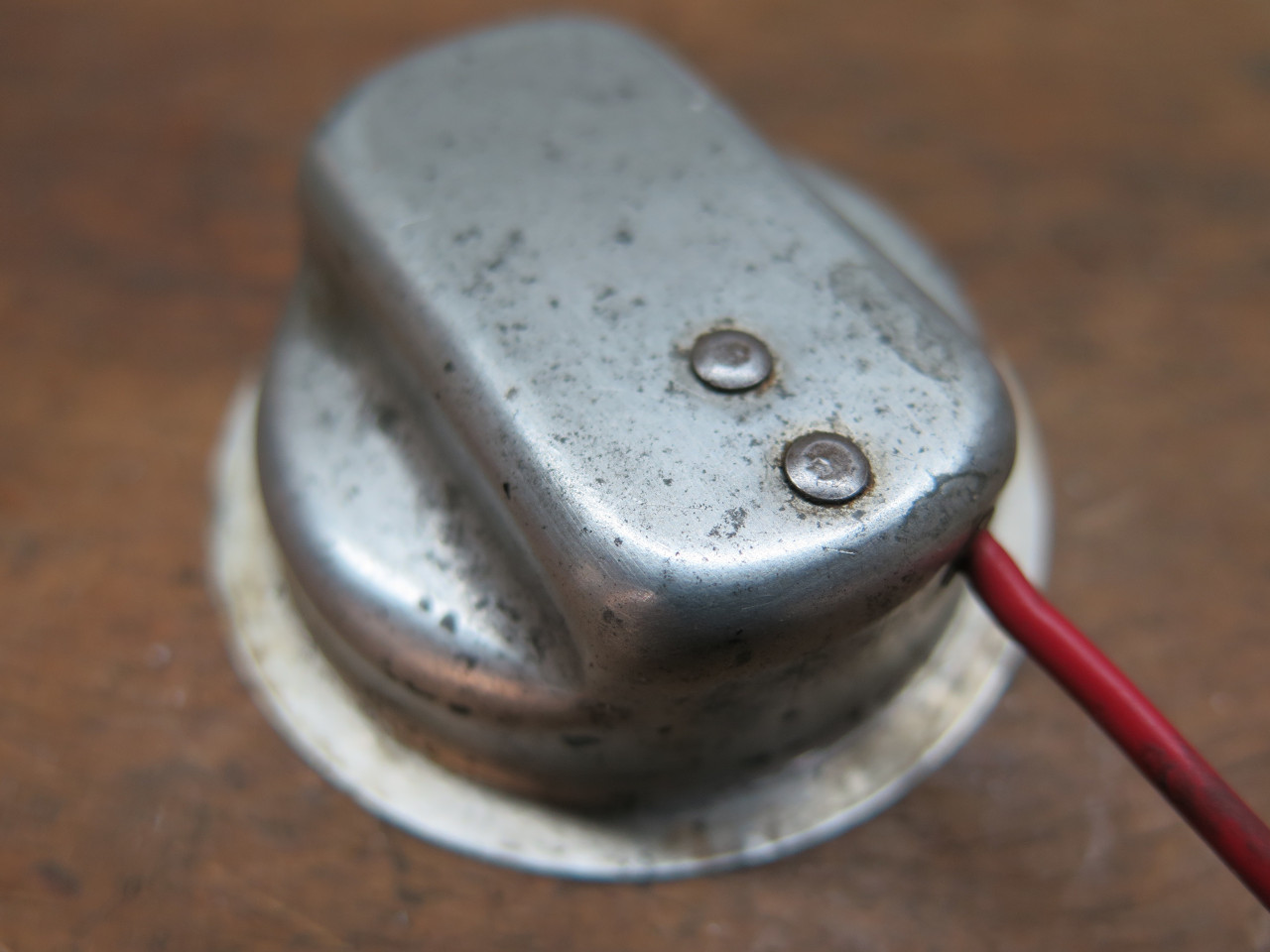
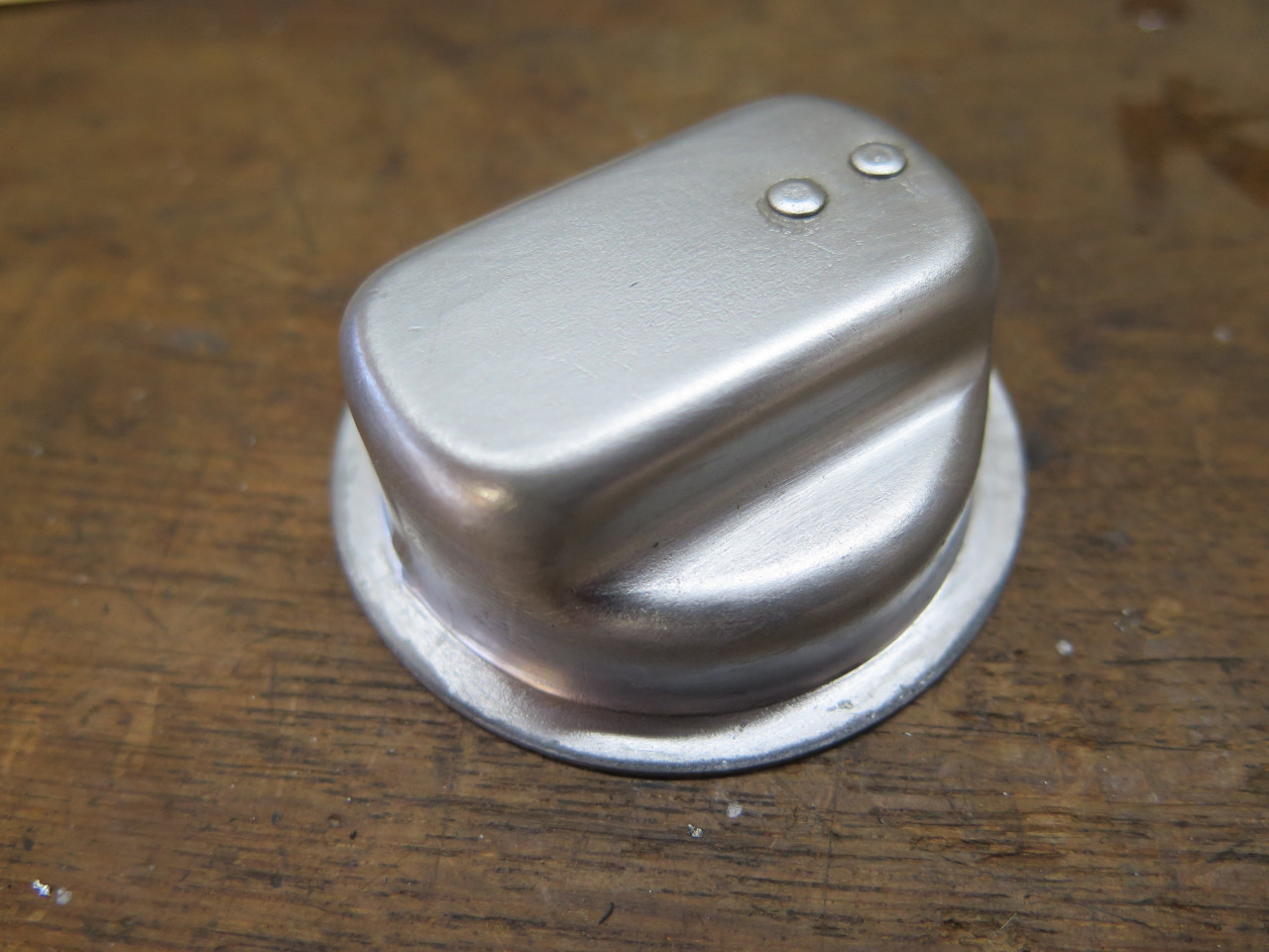
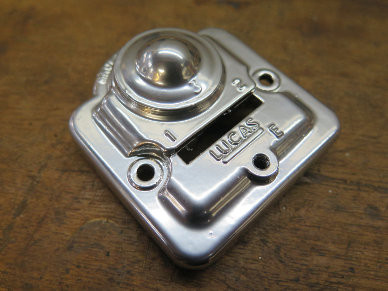
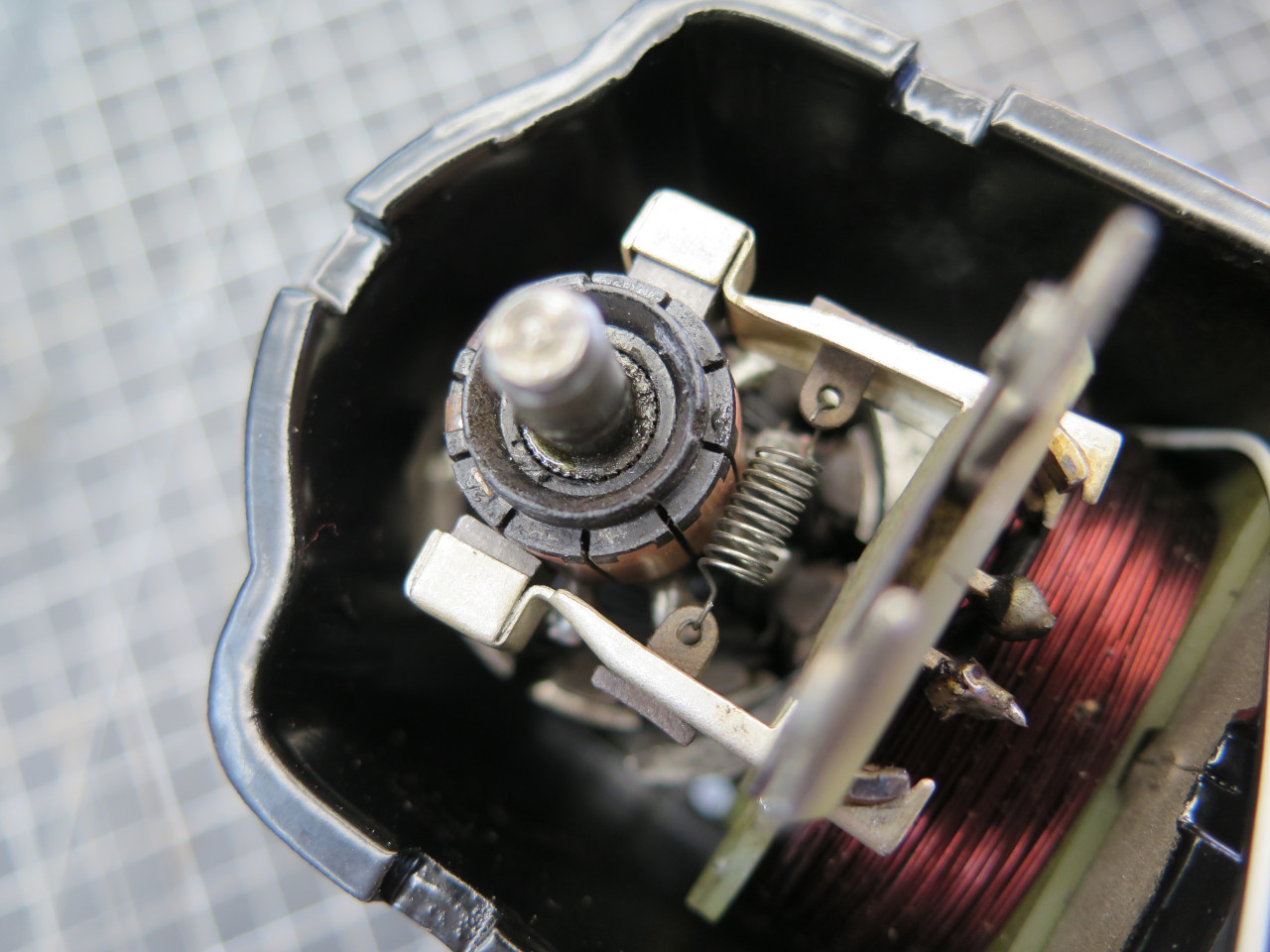
Then there was the park adjustment cap, which holds the park
switch. It was zinc plated steel, and the plating was mostly
intact, but had many blemishes. I removed the plating and
re-plated.
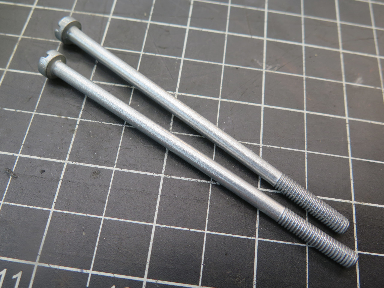
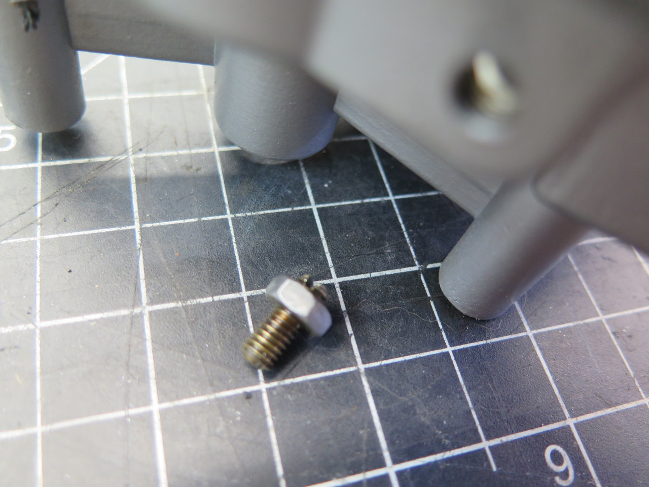
The through screws for the motor got plated.
The end cap for the motor is a pot metal die casting. These can be
polished to look really nice, but it's a fair amount of work, and the
shine won't last. This is a silver powder coat.
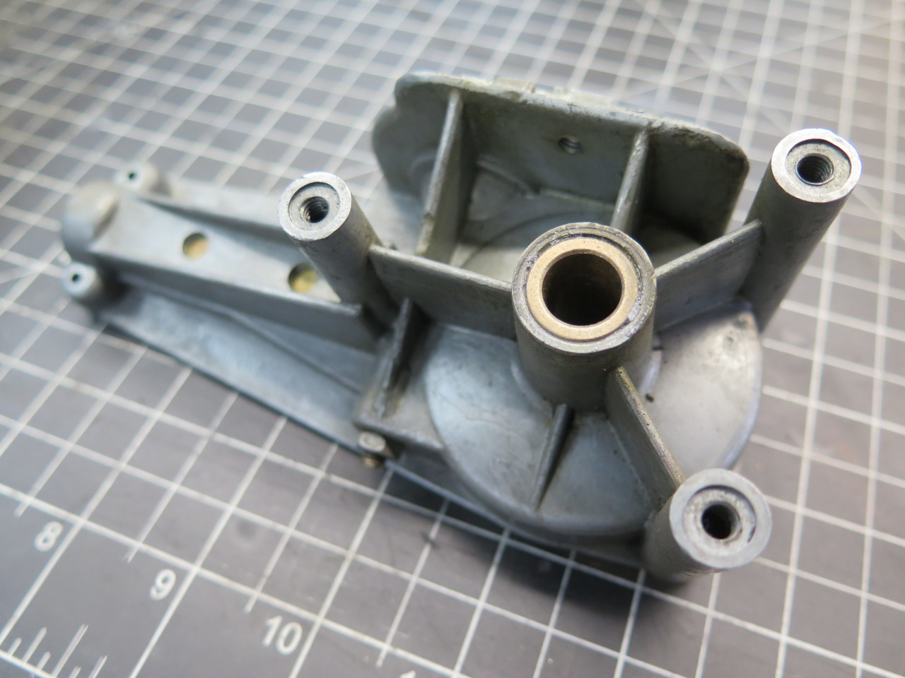
OK, it was finally time to start reassembly. The gearbox body is a
pretty complex die casting, and I didn't think it was a good candidate
for powder coating with all of the small deep recesses, so it just got
painted.

Motor assembly was first. Field/brush assembly was mounted in its
new position, the armature and gear housing were brought home.
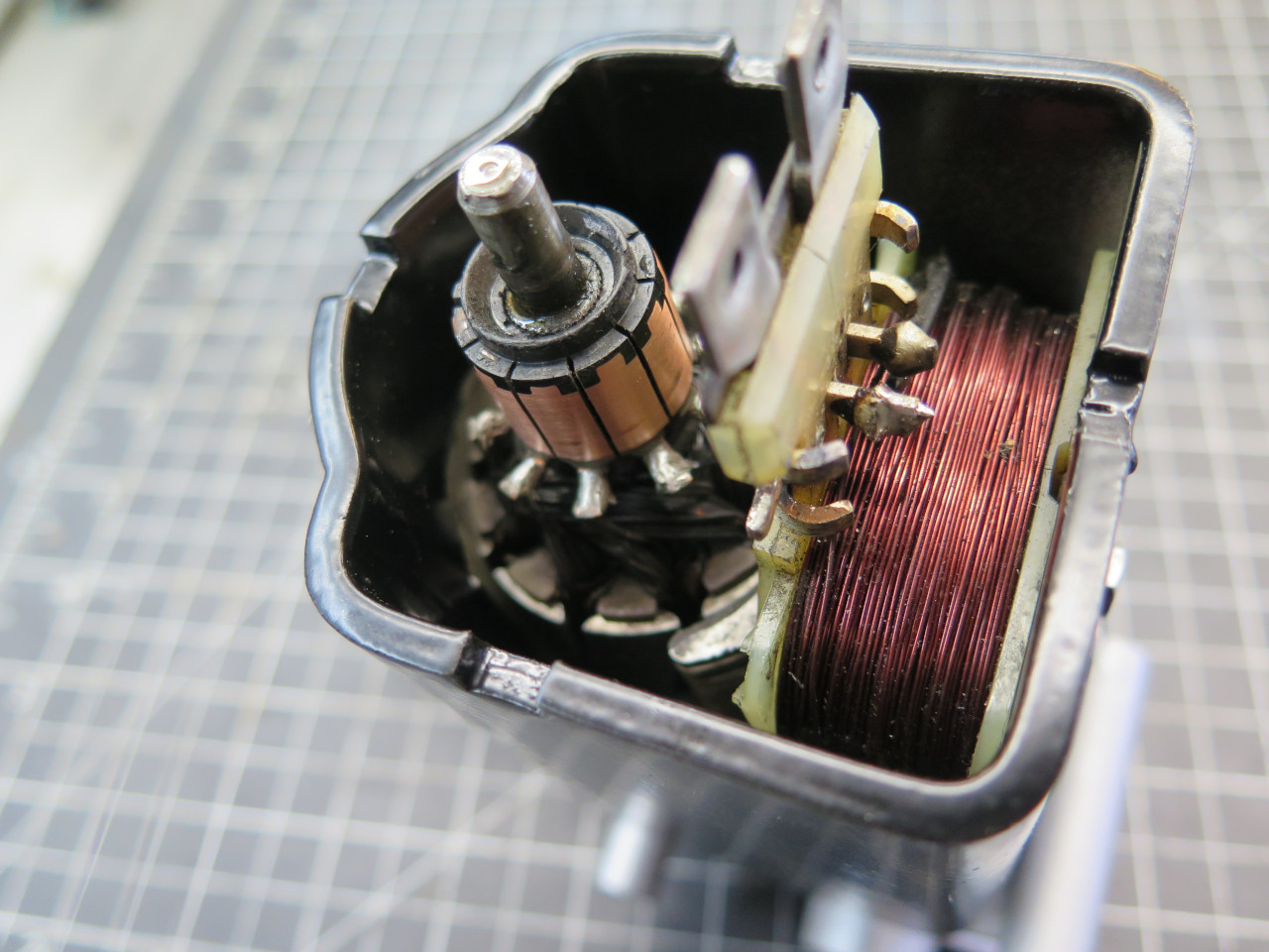
I sensed a problem. The armature seemed to have trouble sliding
into place, and when there, it wouldn't turn. I pulled out and
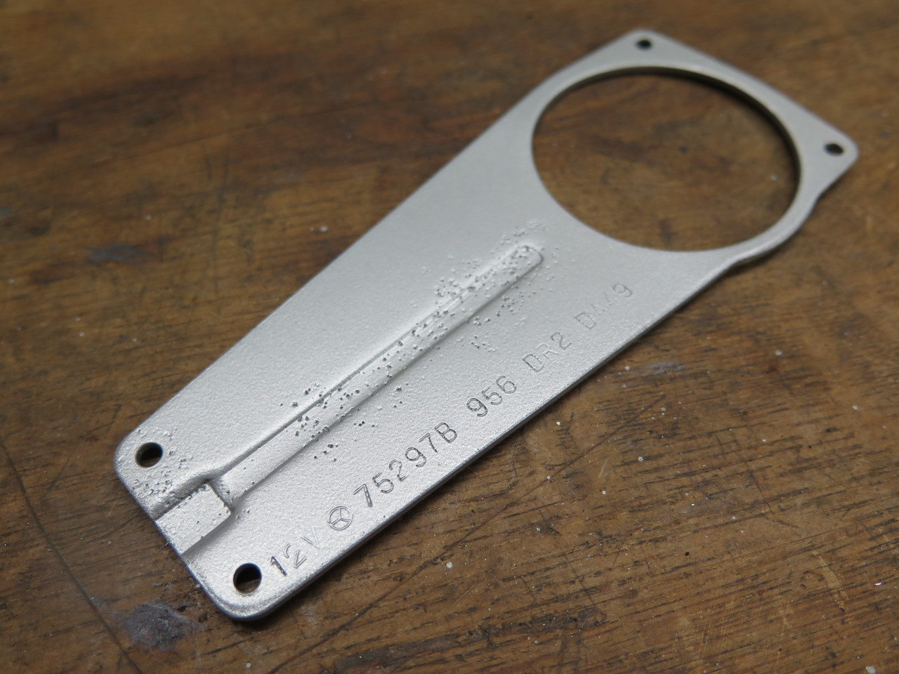
launched a full forensic analysis. This was the problem.
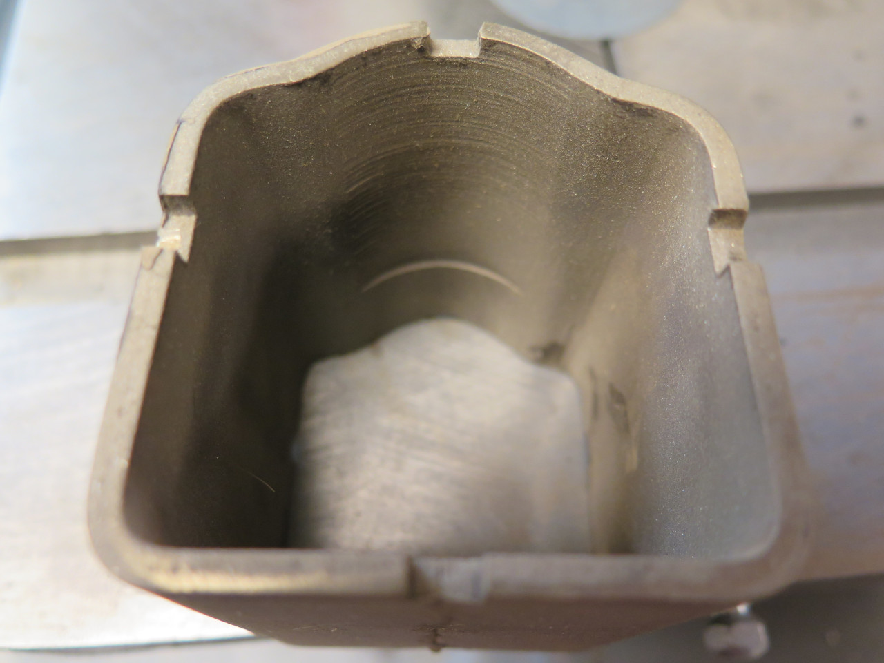
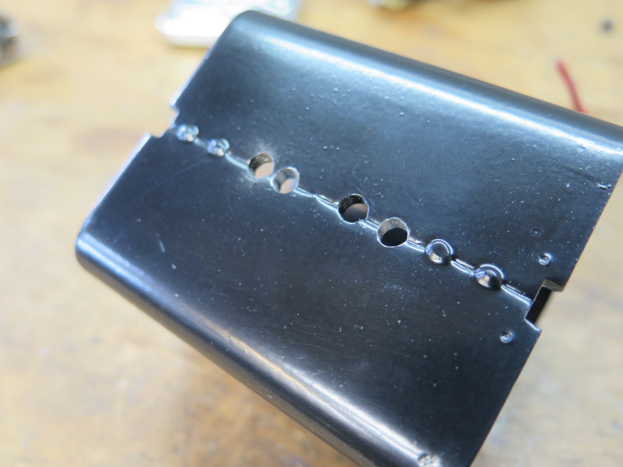
There was a clearance arc machined into the motor housing, but it didn't
extend all the way through. This made the housing not really
symmetrical. The picture was taken after I stripped the
housing. The little step didn't show up to the camera with powder
coat in there.
I realized that since flipping the housing wasn't now an option, the
ugly pitting would be on the visible topside. I knew I couldn't
live with myself if I allowed that, so I decided to strip the housing,
fill the pits, and re-powder coat.
The filler has to be something with good adhesion, and can withstand the
powder coat curing temperatures. I've had good luck with a metal
filled epoxy--JB Weld in this case. I've learned from experience
that just about any filler can outgas during powder curing, so it takes a
heat treating step for the filler before spraying any powder.
So, let's try this again. The housing has some minor waves where
the pitting was. I think the filler might have shrunk slightly in
the outgassing step.
Much better this time. Added the brushes, which is a real joy for anyone with normal sized fingers.
In a flash of forethought, I remembered to add this little armature
float adjuster at this point. The float would be hard to measure
after the main gear was installed. I couldn't find a float spec,
but figured around 0.010" seemed about right. I set it by eye.
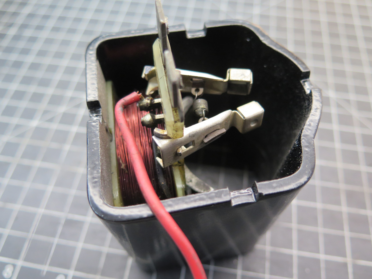
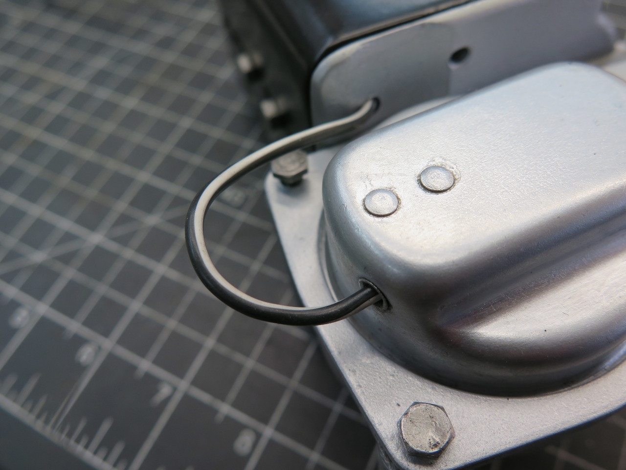
Before closing up the motor, this silly wire has to be connected.
It is part of the park circuit, and runs from the park switch to the
earth side motor terminal. The circuit keeps the motor running
when the dash wiper switch is turned off until the wiper blades are
parked. I'm not sure if the red wire I found on the unit was
original, but black or some variant seemed to be a better choice.
This is black with a white marker.
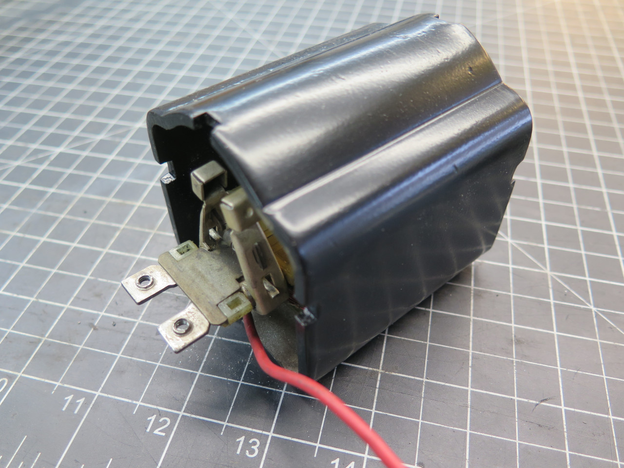
Then the mechanical parts can go in.
Then button 'er up.
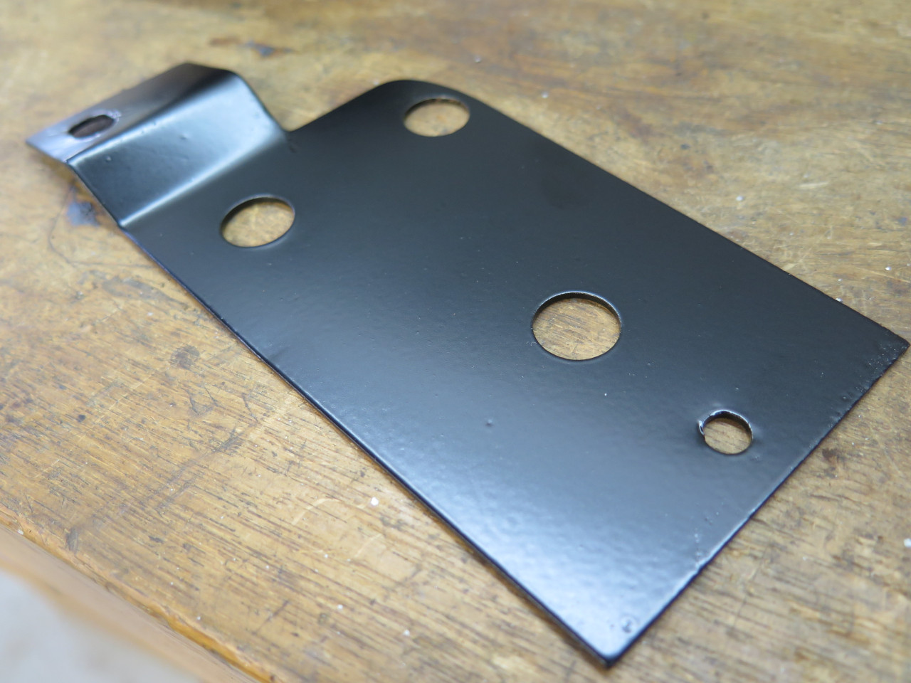
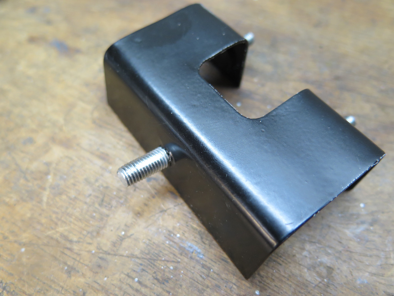
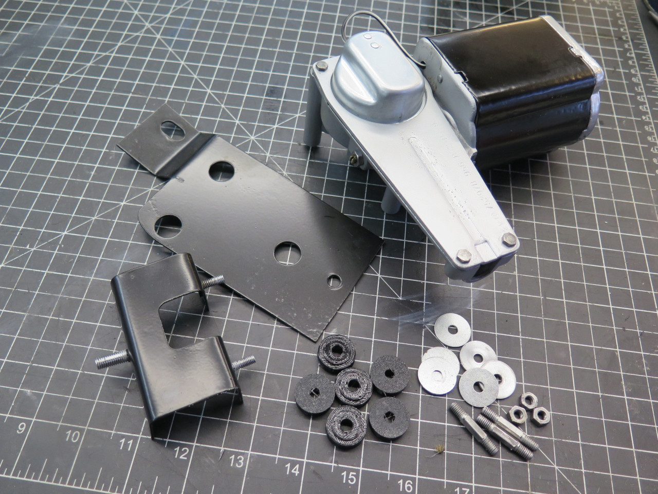
The only thing left then was the mounting brackets. There is a
flat bracket, and a little pedestal. The flat bracket had three
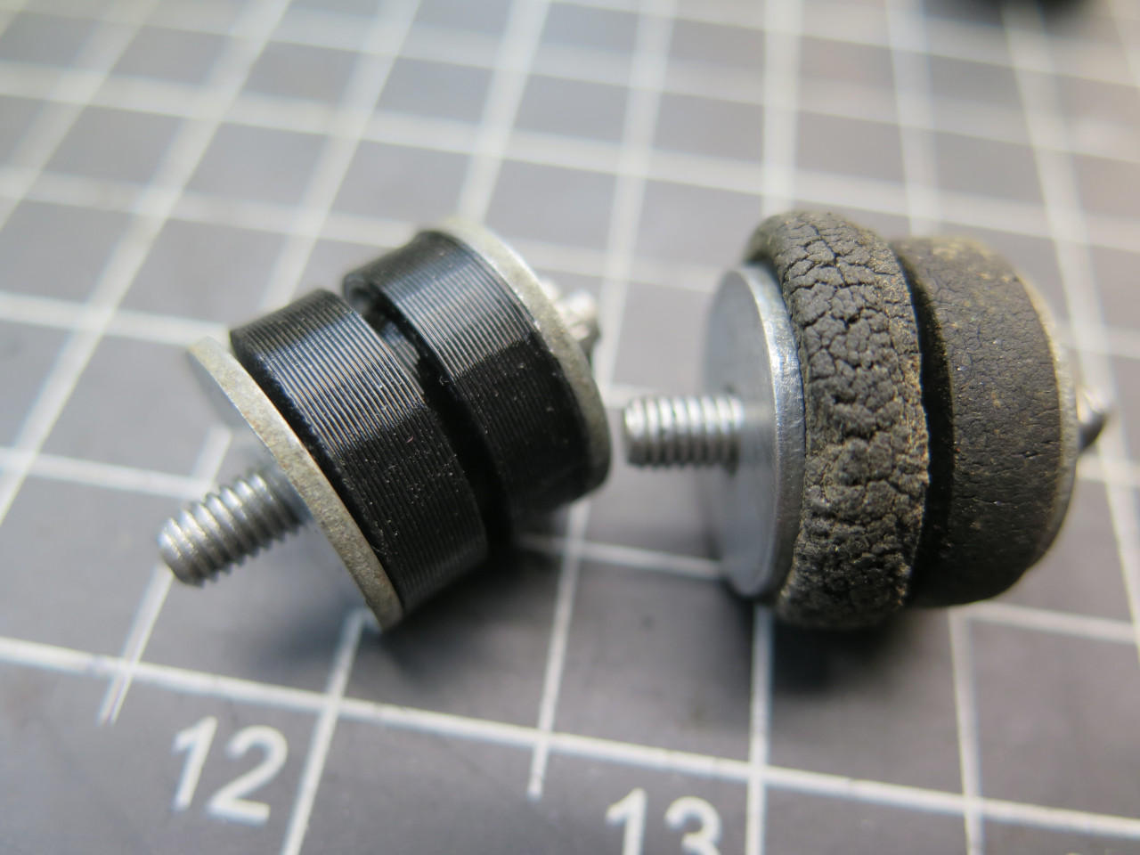
grommets to isolate the motor from the car.
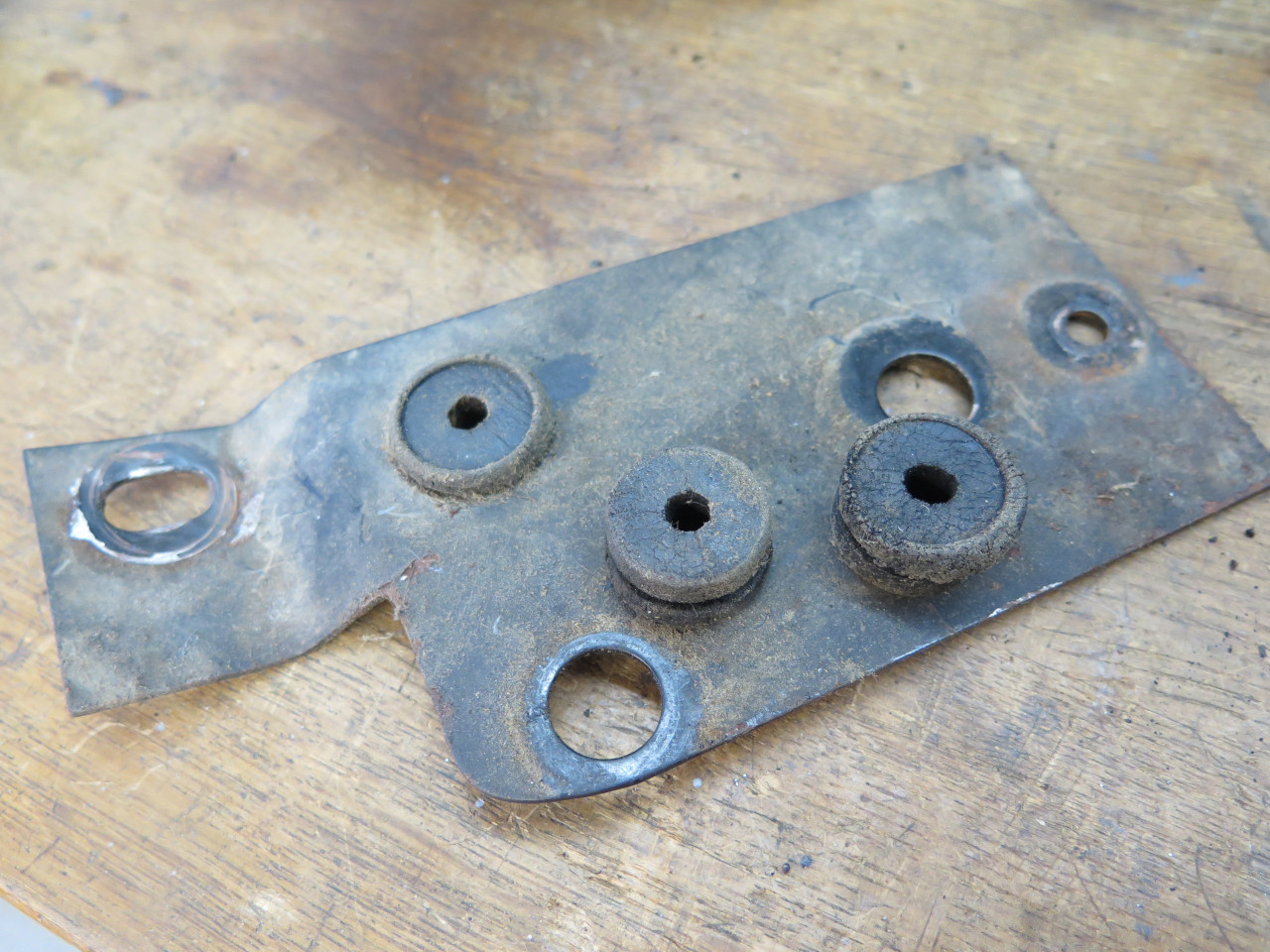
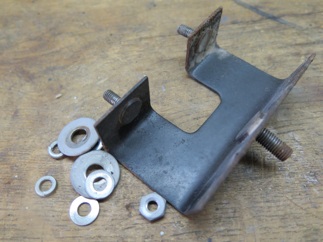
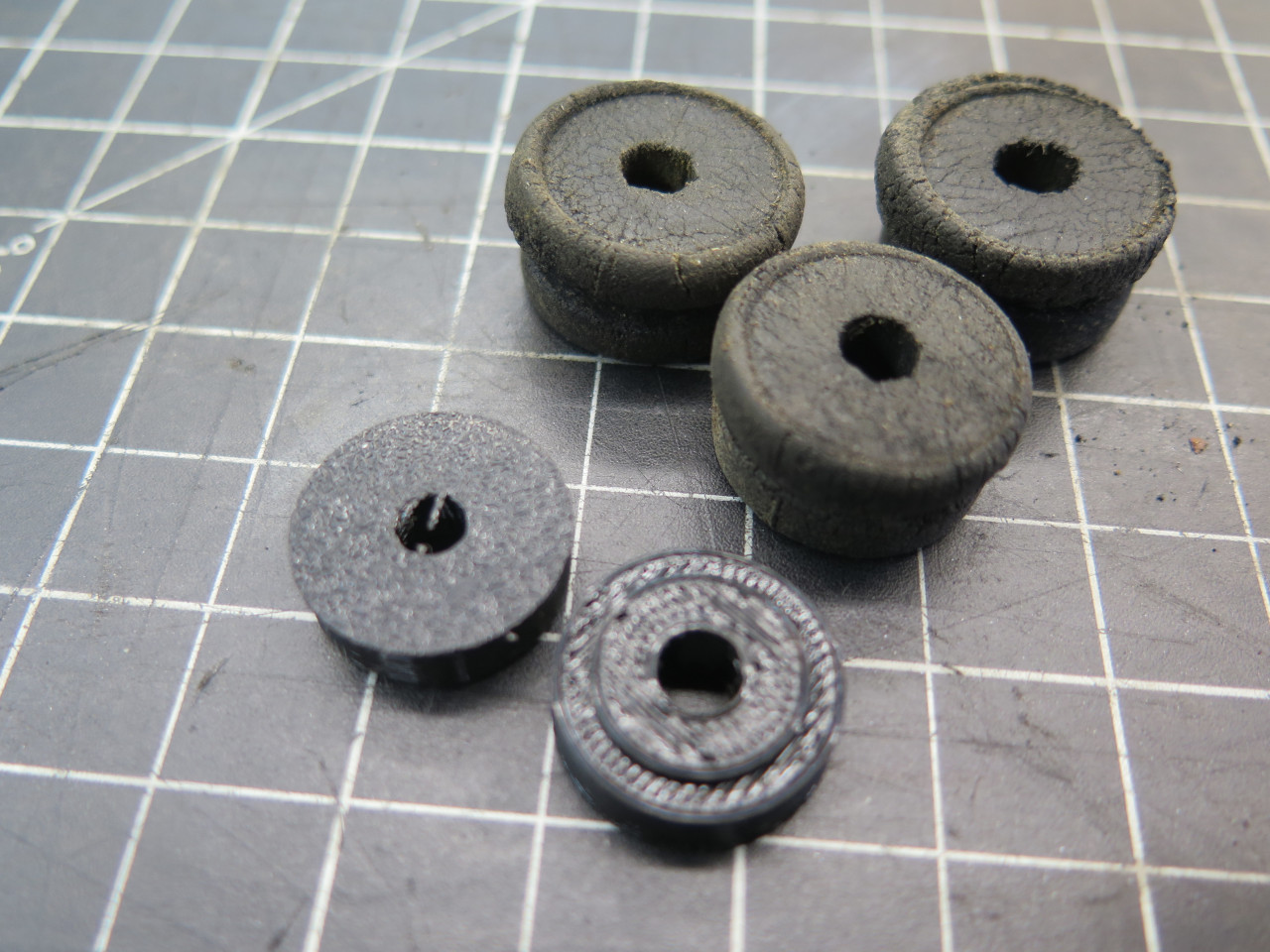
The grommets were pretty much toast. They were a combination of
squishy and crispy. I don't doubt that I probably could have found
something pretty close to these as replacements, but it seemed much
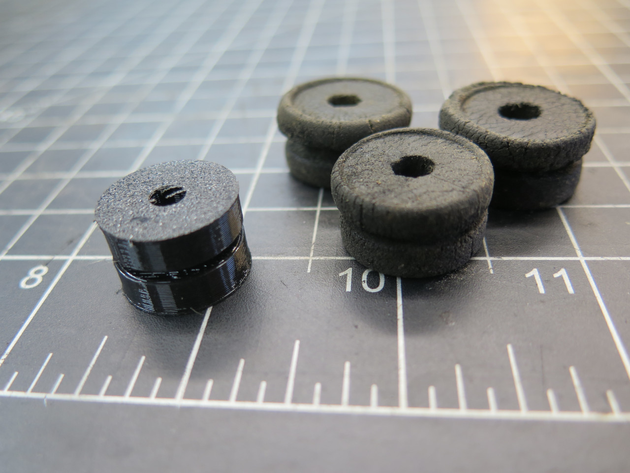
simpler to just 3D print some. CAD only took 20 minutes or so, and
around an hour to print a set. They are made of TPU--a soft
urethane rubber material. I made each grommet as two halves.
This made them trivial to design and easy to print, and they don't have
to be forced into the hole in the bracket.
The brackets got powder coated.
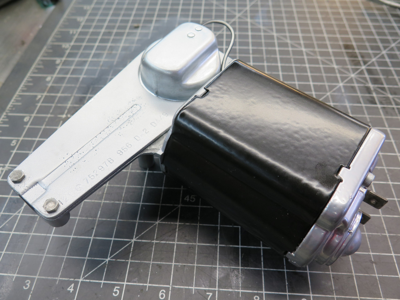
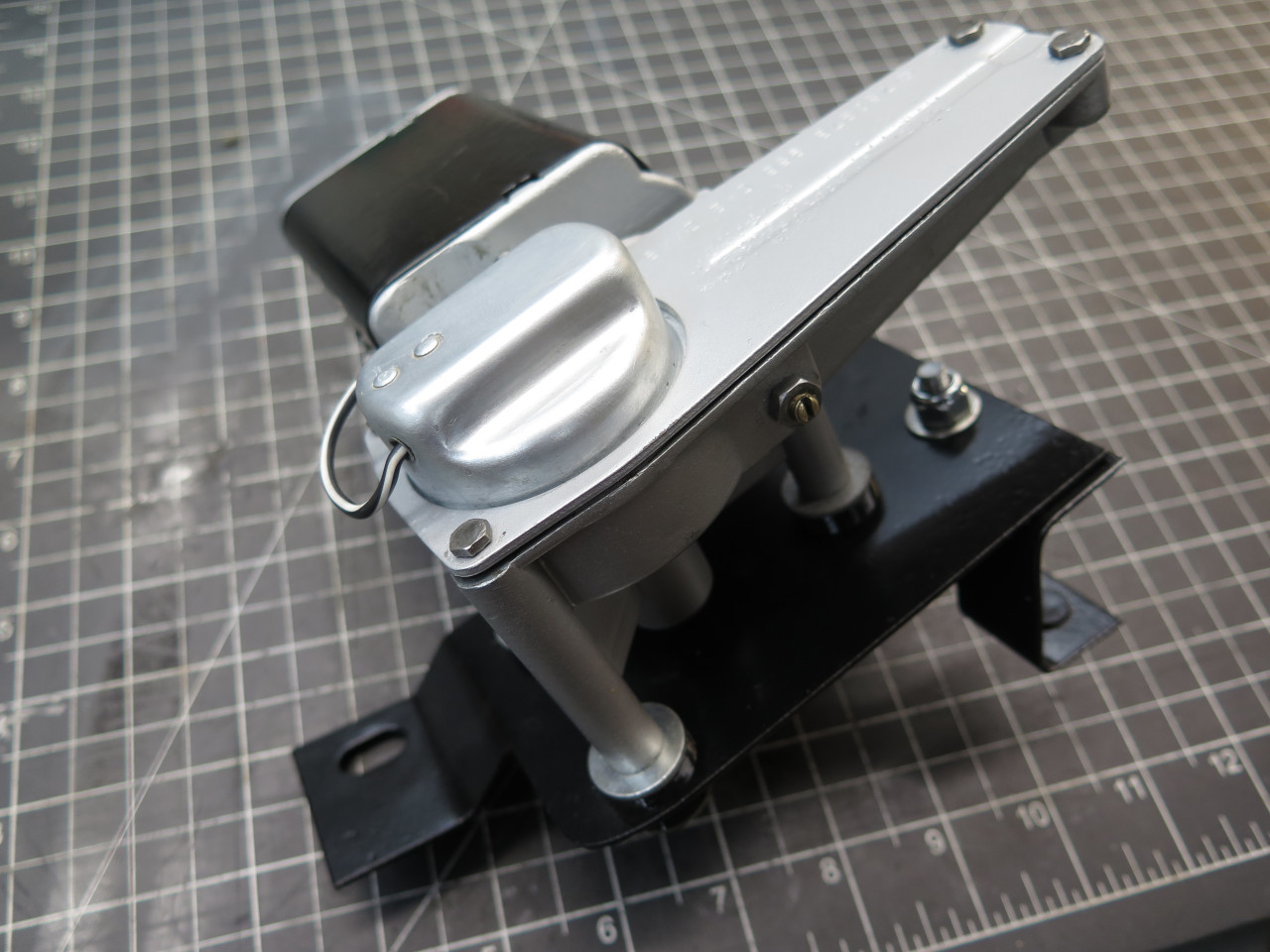
Ready for final assembly.
On the shelf with this dude.
This was a pretty fun, low stress job, even with the backtrack of the
motor housing. I'm still a little leery of the burnt-looking
armature windings, so I'll have to watch that. Might have to
rewind at some point.
Cost was essentially zero--just some consumables.
Comments to Ed at elhollin1@yahoo.com
To my other MGA pages