To my other GT6 pages
October 2, 2022
Air Induction & Air Box
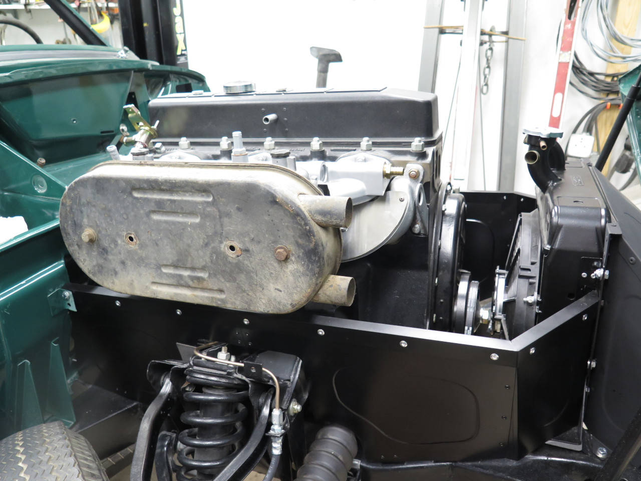
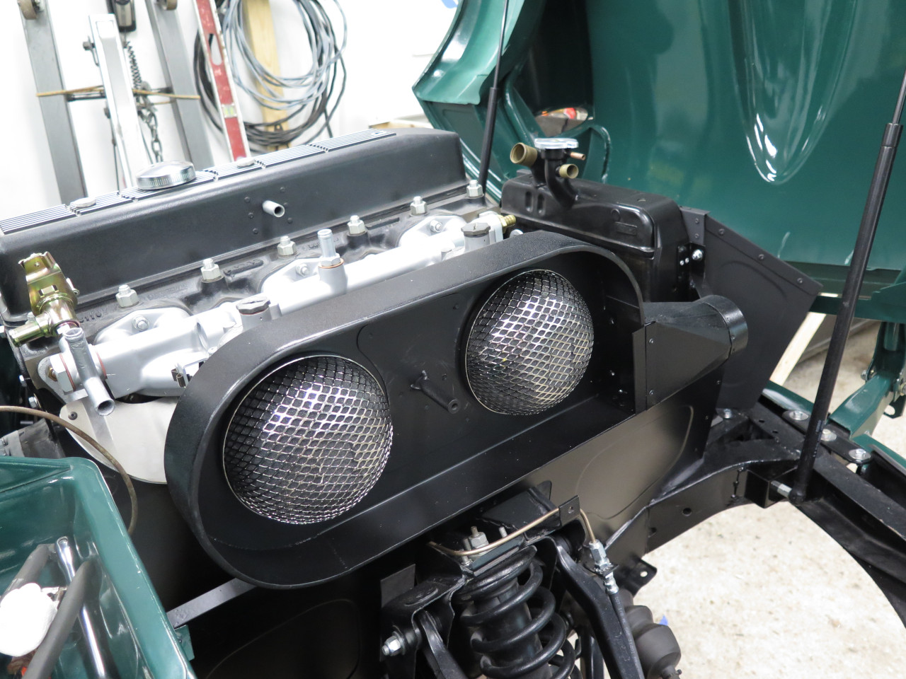
The next thing I pulled from my GT6 box o' parts was the air box.
I'm not sure if all GT6 cars used this same air box, but at least most
of them did. It's basically a two-part steel enclosure that holds
two pancake filters, one for each carb. There is a pair of
snorkel-like protuberances at the front as air inlets. Mine was
dirty and rusty, but intact.

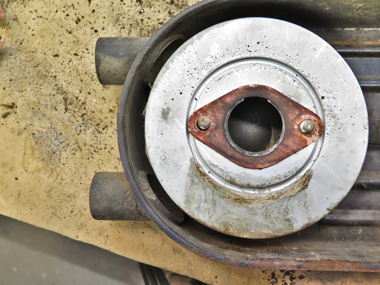
I looked at the device pretty closely. One thing that struck me
was the size of the snorkels. They each measure less than 1 3/8"
in diameter, which is smaller than the carb throats. Now, this is
not my area of expertise, but it seemed to me that this would represent a
restriction. Beyond that, I noticed how small the clearance
seemed between the internal snorkel ends and the leading filter.
It's only around 5/16". This may be fine for that front carb, but
again, it seems like it would be a restriction for the rear one.
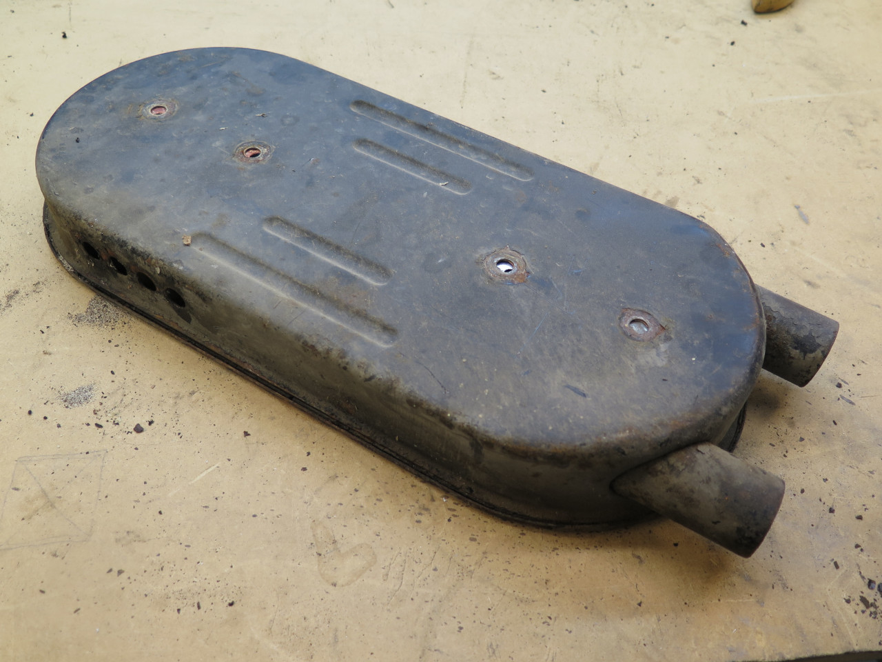
Maybe someone at Triumph had the same concerns, because there were also
four half-inch holes in the bottom of the airbox back near the rear
filter. As far as raw area goes, those four holes provide only
about half the area of one of the snorkels.

In my child-like view of air flow restrictions, it seemed to me that this airbox could be done better.
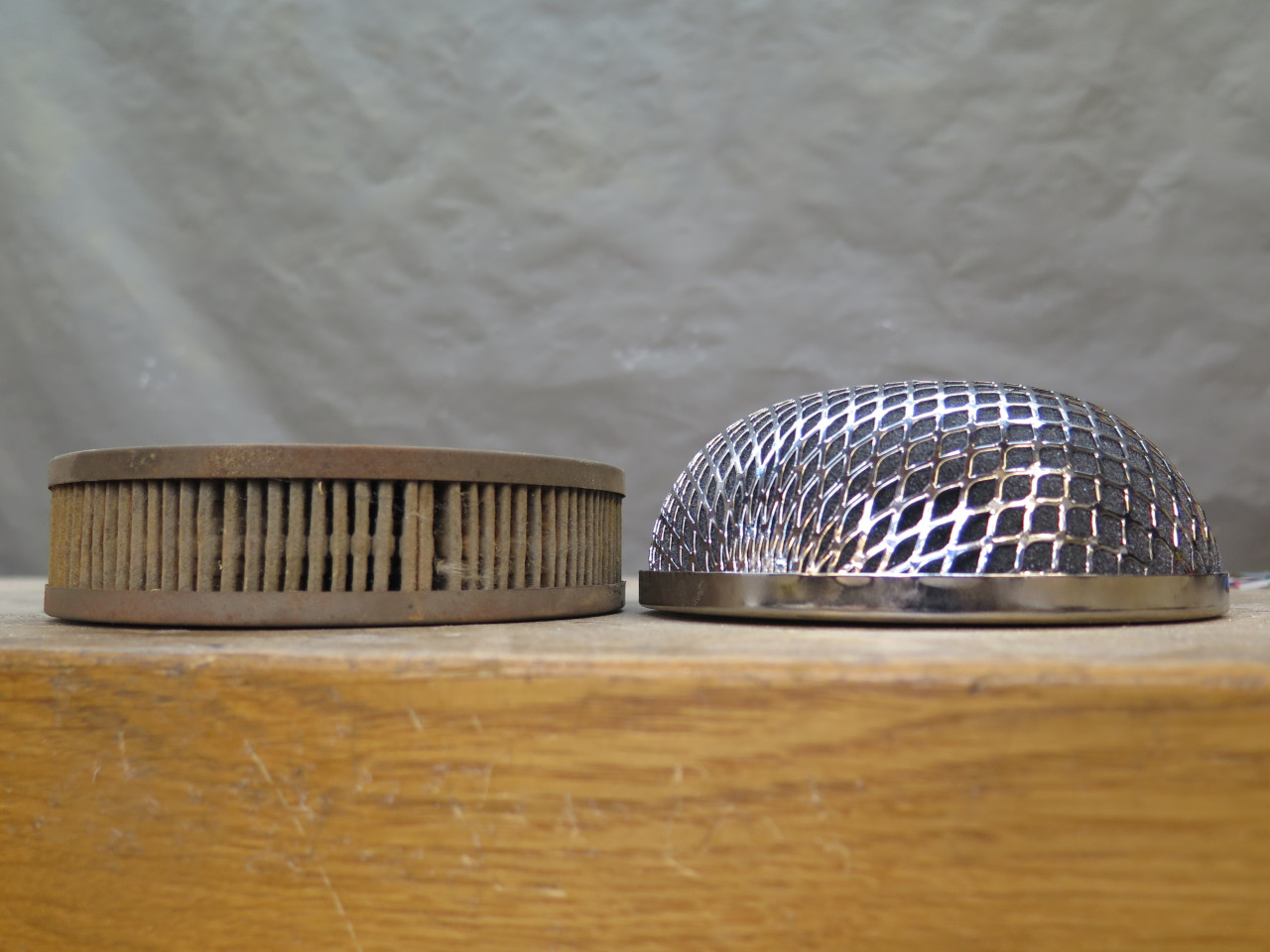
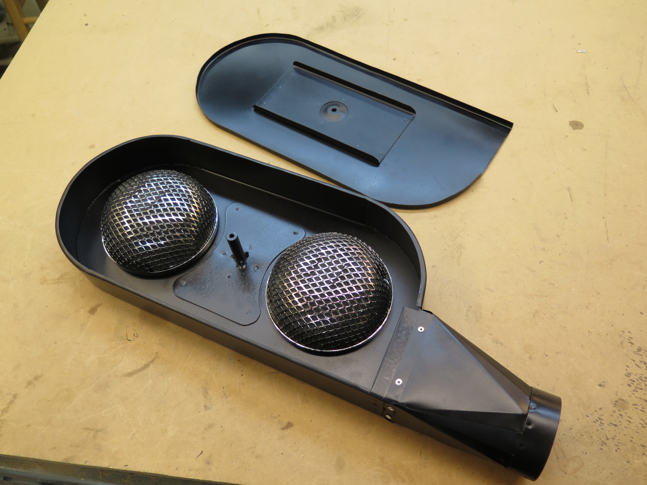
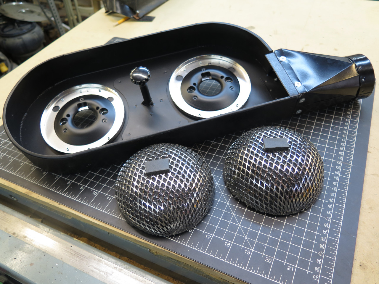
Maybe more compact filters would help. These are so-called
"Ramflo" type filters. I believe that true Ramflo filters come
from an Australian outfit, and these are decent copies. They still
weren't exactly cheap. They use washable foam elements that can be used
dry or with oil impregnation. They are smaller in diameter, which
would help with air flow around them.
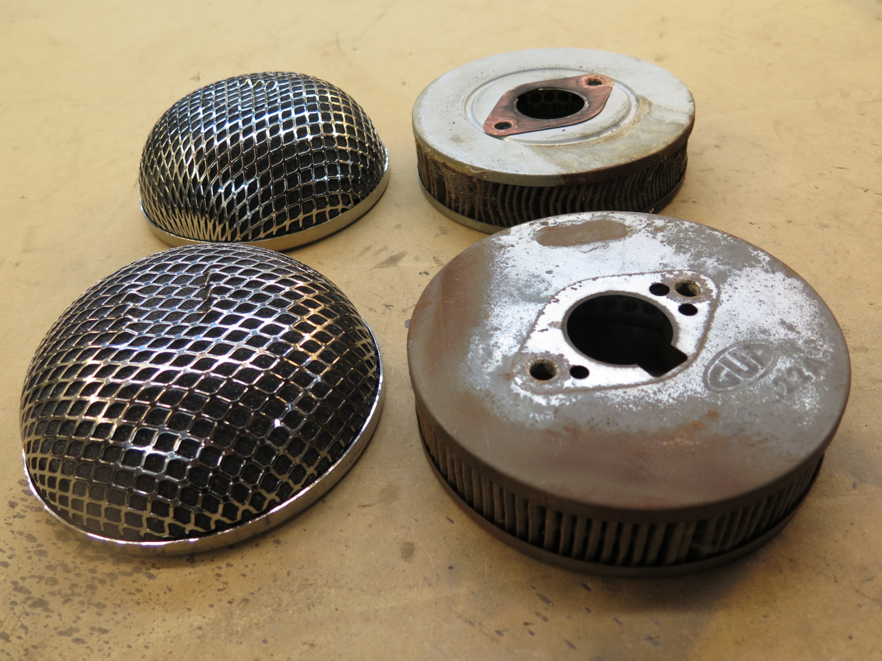
But they are also quite a bit thicker than the stock filters.
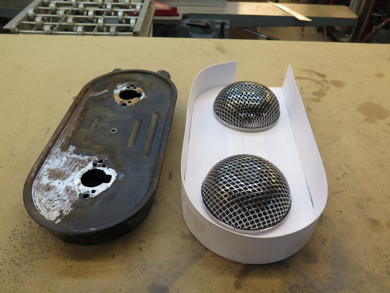
I thought about it quite a bit, and finally decided to pitch the
original airbox completely and make a new one more to my liking.
There are of course space limitations, but even so, I could make the new
box bigger in all dimensions. I did pay homage to the original
design by sticking to the same general shape. A cardboard mockup
came first.
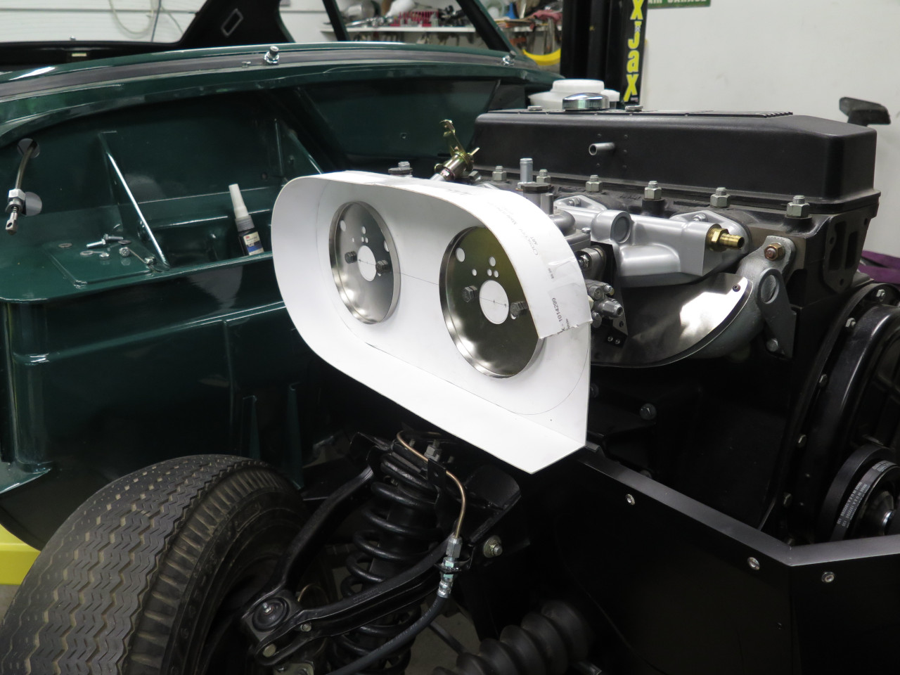

Not seeing any obvious problems, I moved on to metal.


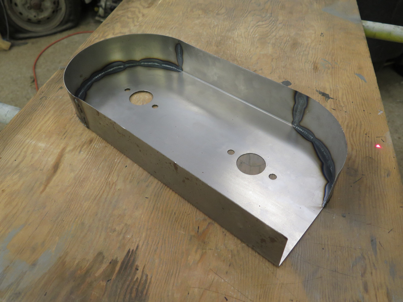
Sanity check #1

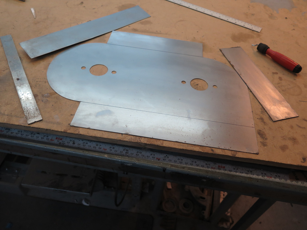
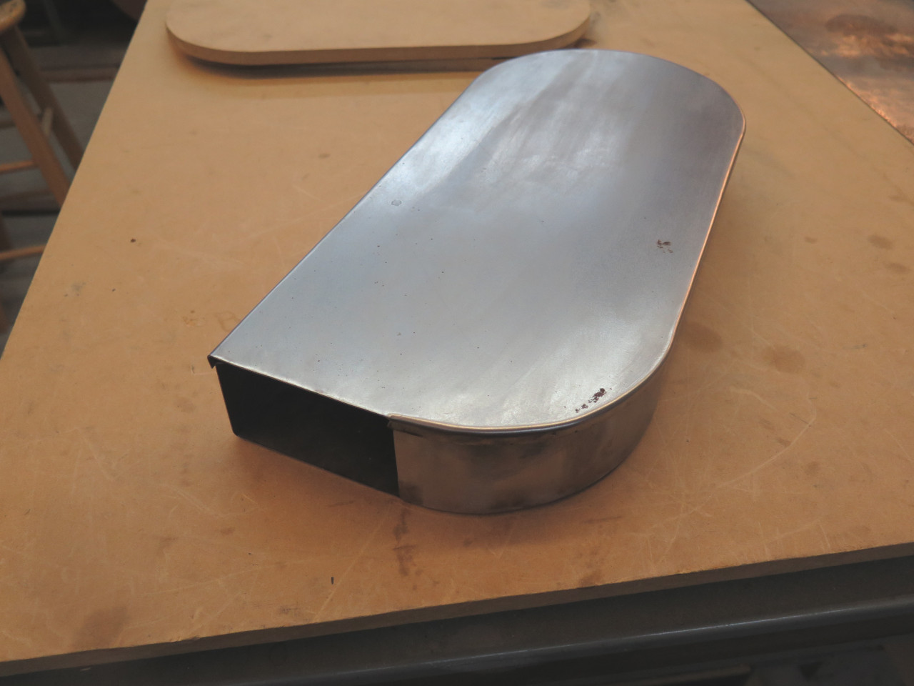
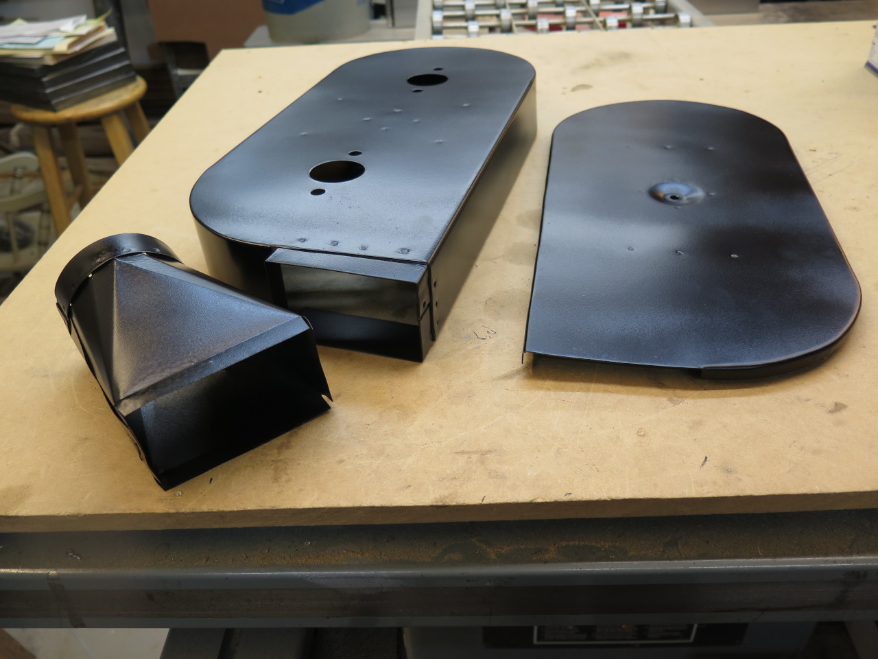
Made a cover for the box...

...and a couple of stiffeners for inside.


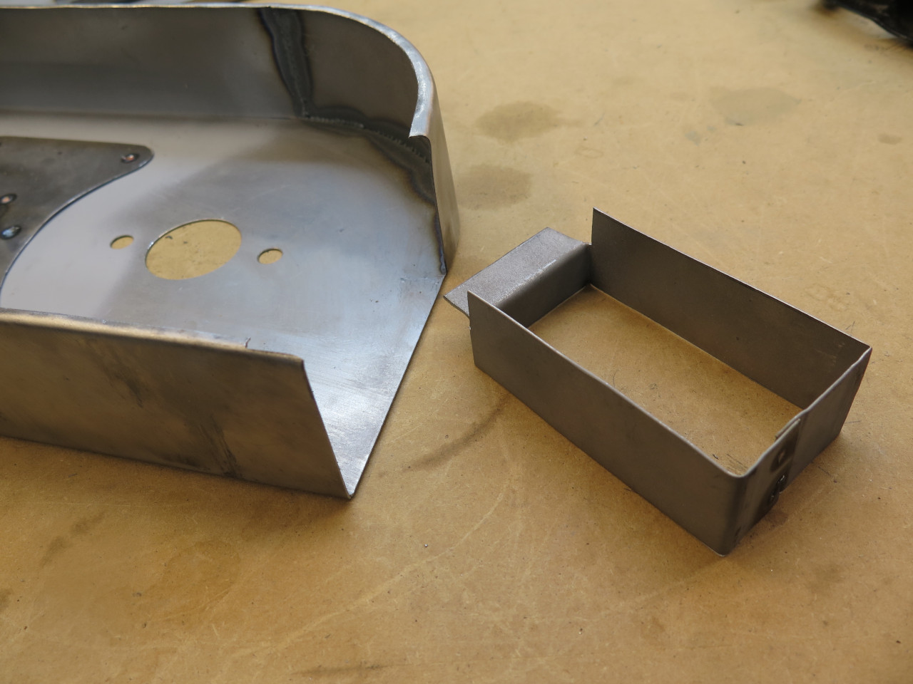
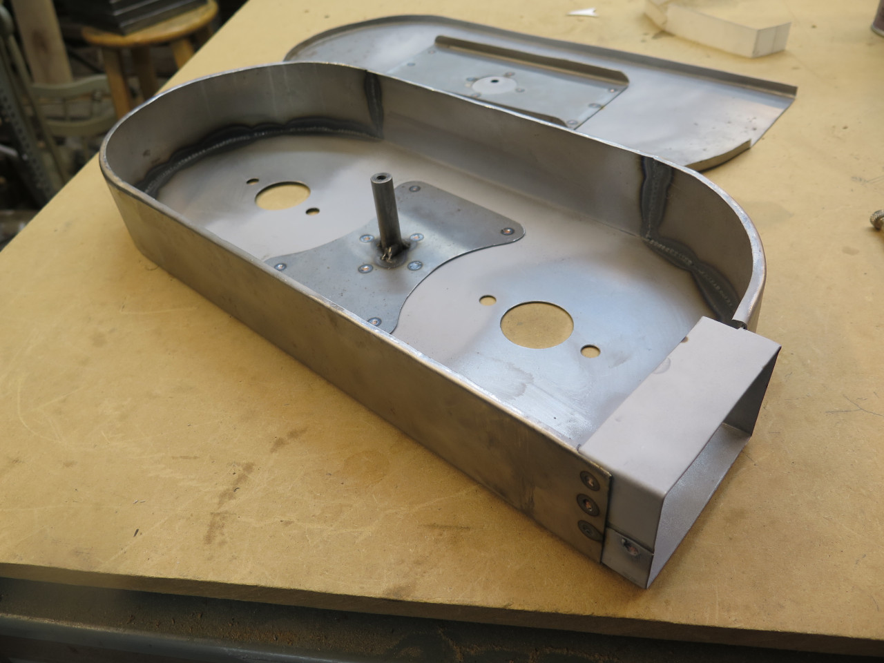
And a little nose piece. I was noodling some ideas for air induction that would connect to the nose piece.
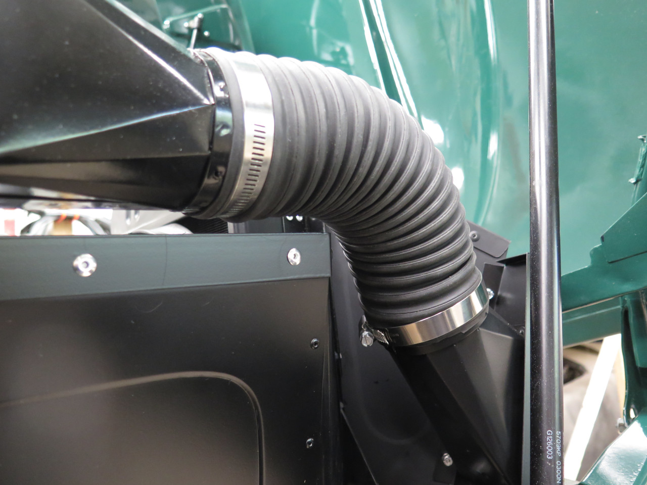
Shortly after this, I decided that a flexible duct to bring fresh air
from somewhere at the front of the car would be a cool idea. A
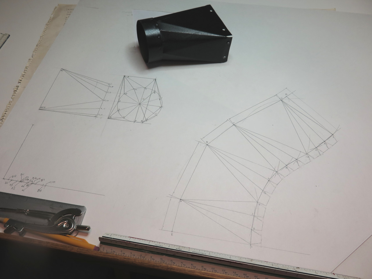
sense of proportion led me to land on 3 inch round duct. This of
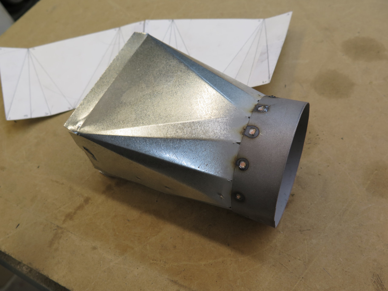
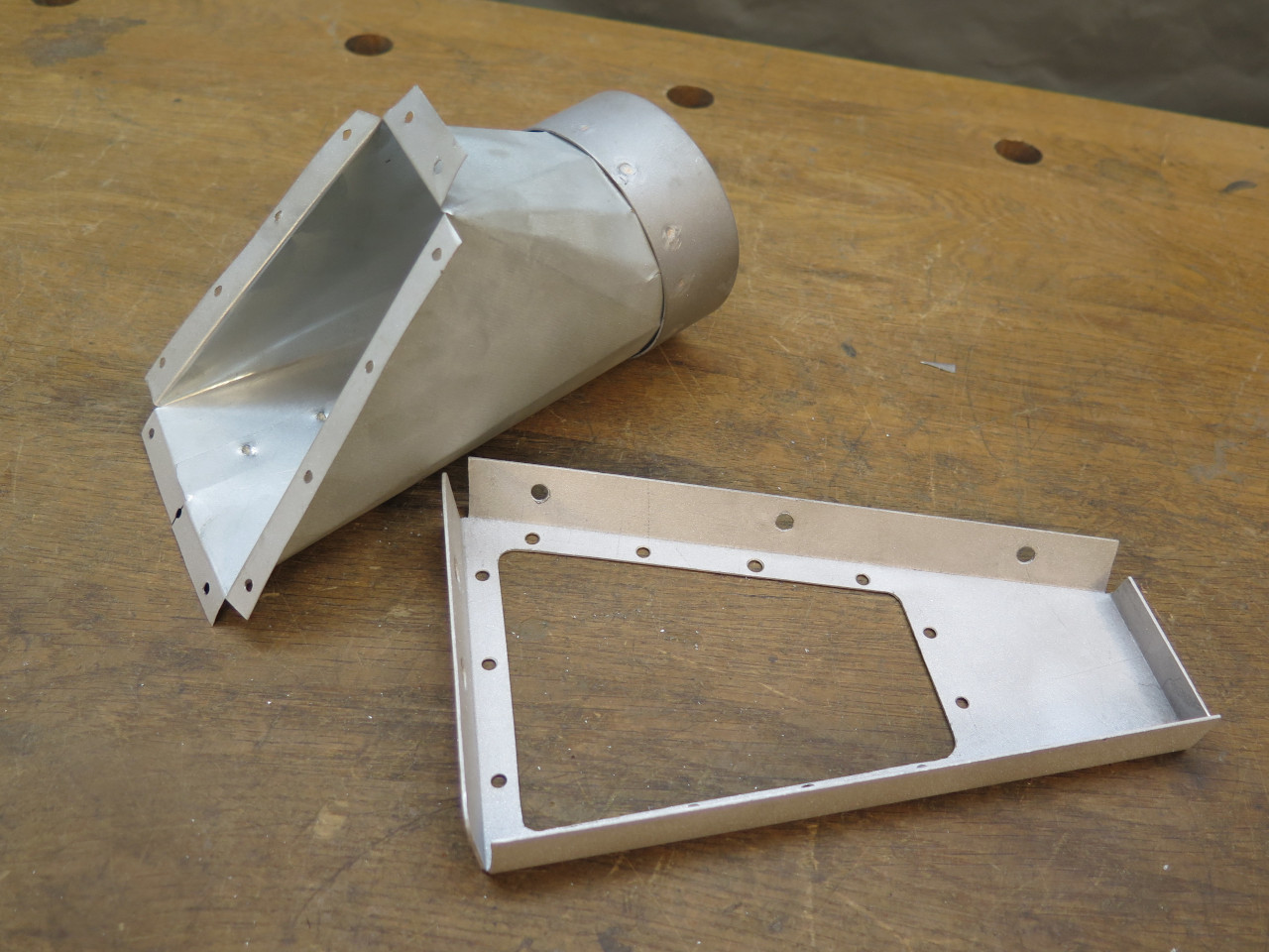
course required a transition piece from the 2 1/4" x 4" nose piece
opening to the 3" duct. For some inexplicable reason, I still
remember from highschool drafting class how to lay out sheet metal
transitions graphically.
Some prep and a shot of a two-part epoxy primer.
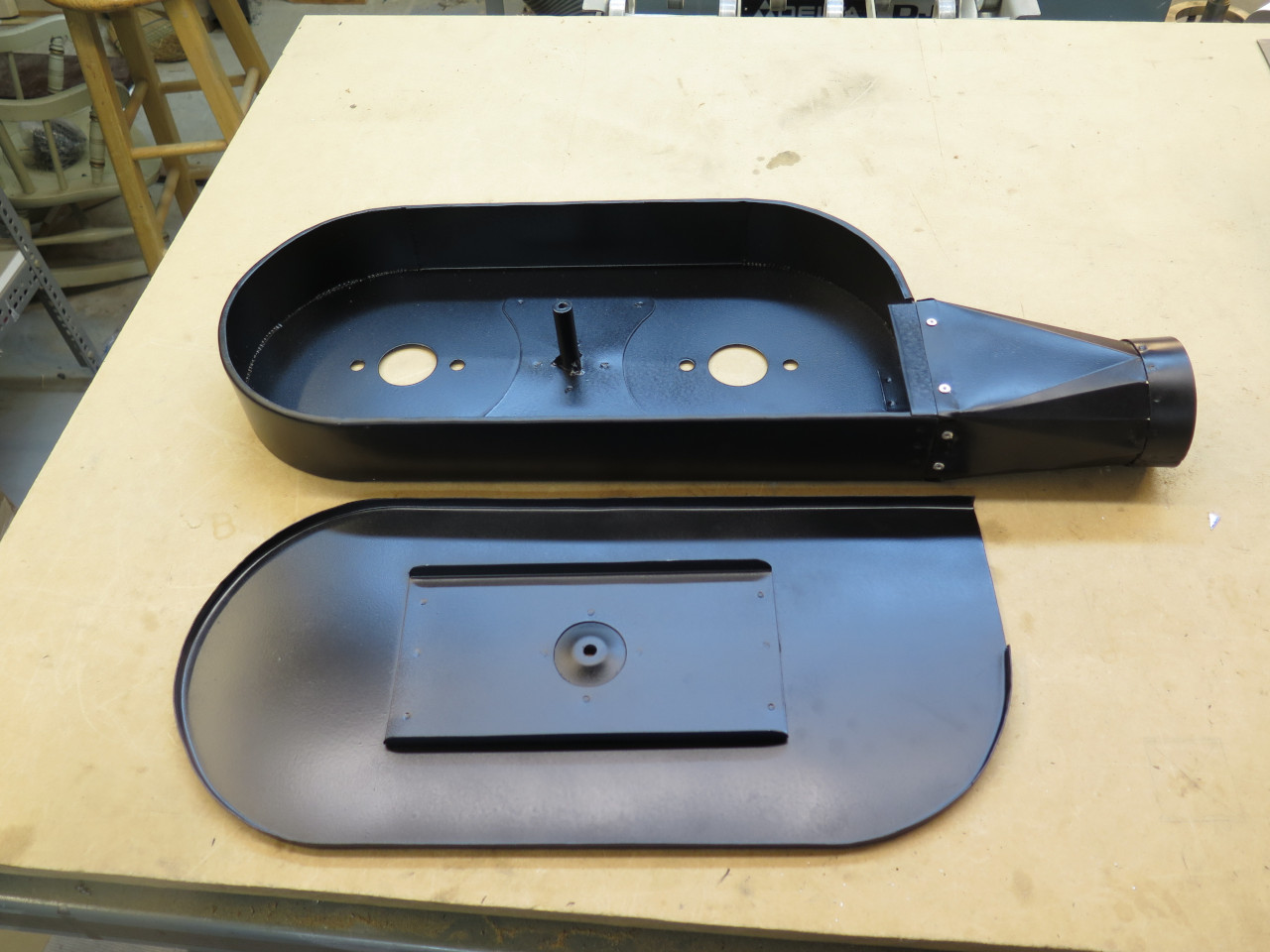
Getting close now. A seal for the cover.

Sanity check #2:

Suddenly, tragedy struck.
I knew the clearance between the enlarged box and the right bonnet lift strut
was a little close with the bonnet down, but I was satisfied that it
was OK. What I forgot to account for was that the 3 inch end of
the transition piece stuck out beyond the plane of the box, and the
strut fouled it.

Oh well, back to the drawing board. Literally.
This time, the round port was offset about 3/4" inboard.


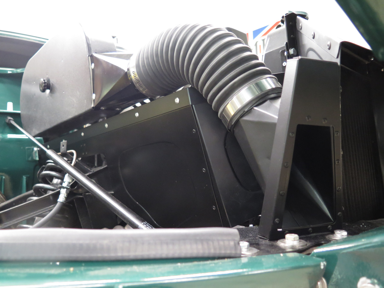
So, with that blunder smoothed over, it was time to think about where
this 3 inch duct was going to go. At first, I'd planned to somehow
connect the duct to the right side wing of the radiator cowl. I
think that would have worked, but I ended up going a different
way. I eyed the space just to the right of the cowl. It
would be an odd shape, but it seemed to be just big enough. First, a heavy paper pattern, then
aluminum:
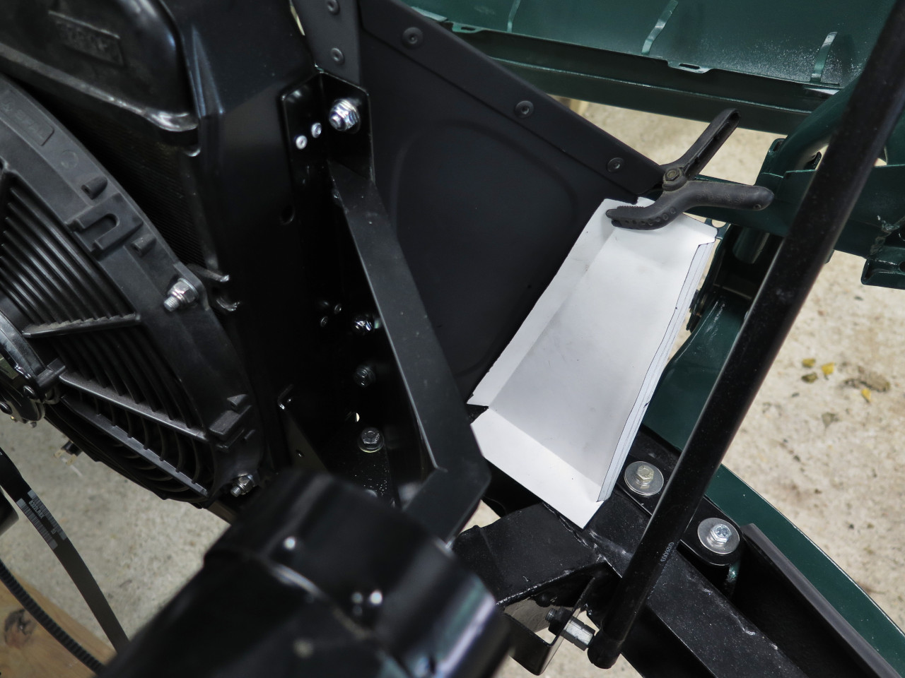

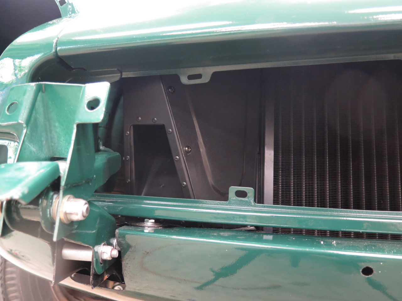
The piece would attach to the edge of the cowl.
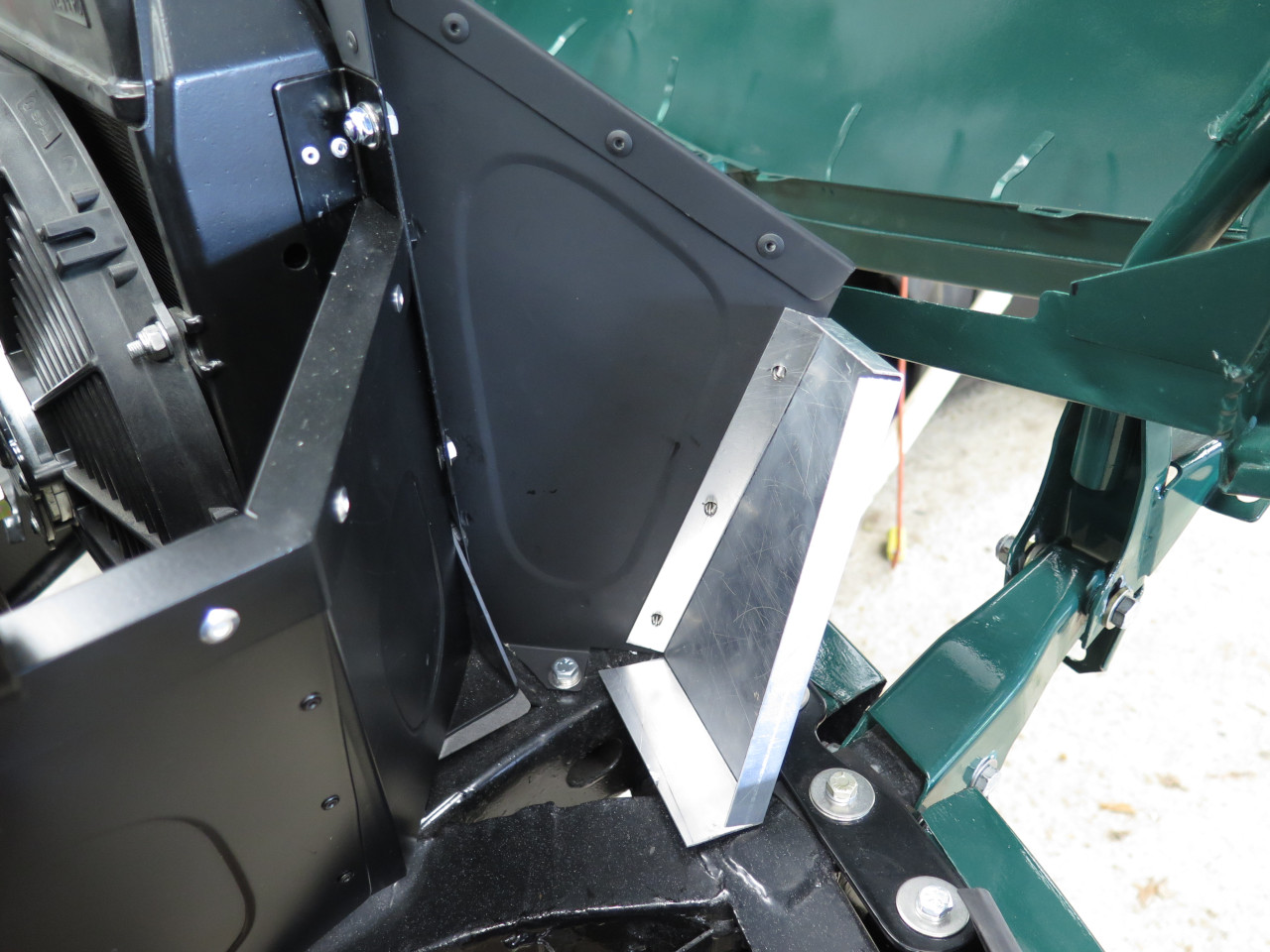
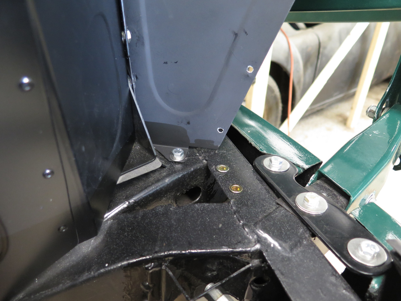
Serendipitously, there were two holes in the frame cross member just under the bottom
flange of this new piece, and they were perfectly sized for a couple of
1/4" rivnuts. Those holes are probably there for a reason--a
horn, maybe, but I'll cross that bridge later.
I envisioned another transition from the duct to a mouth in this new
plate. I fooled around with some duct to see how it could approach
the plate. I found an arrangement that looked OK, but it meant
that the 3 inch port of the transition would be at an odd compound angle
to the plate. Now, I'm pretty sure that the graphical method of
laying out the transition could accommodate this, but I'd have to
measure the angles, which seemed hard.

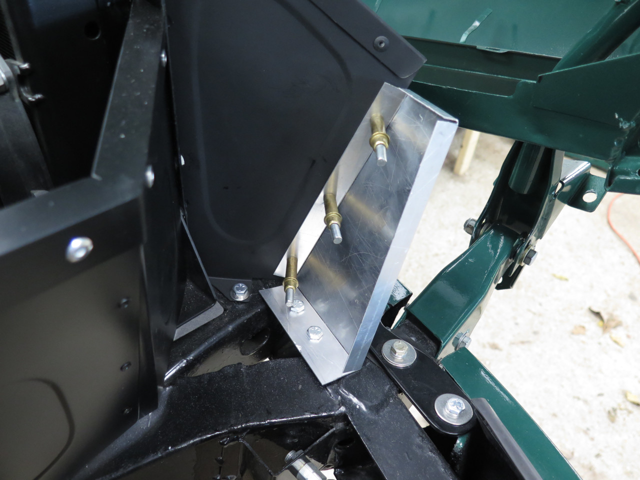
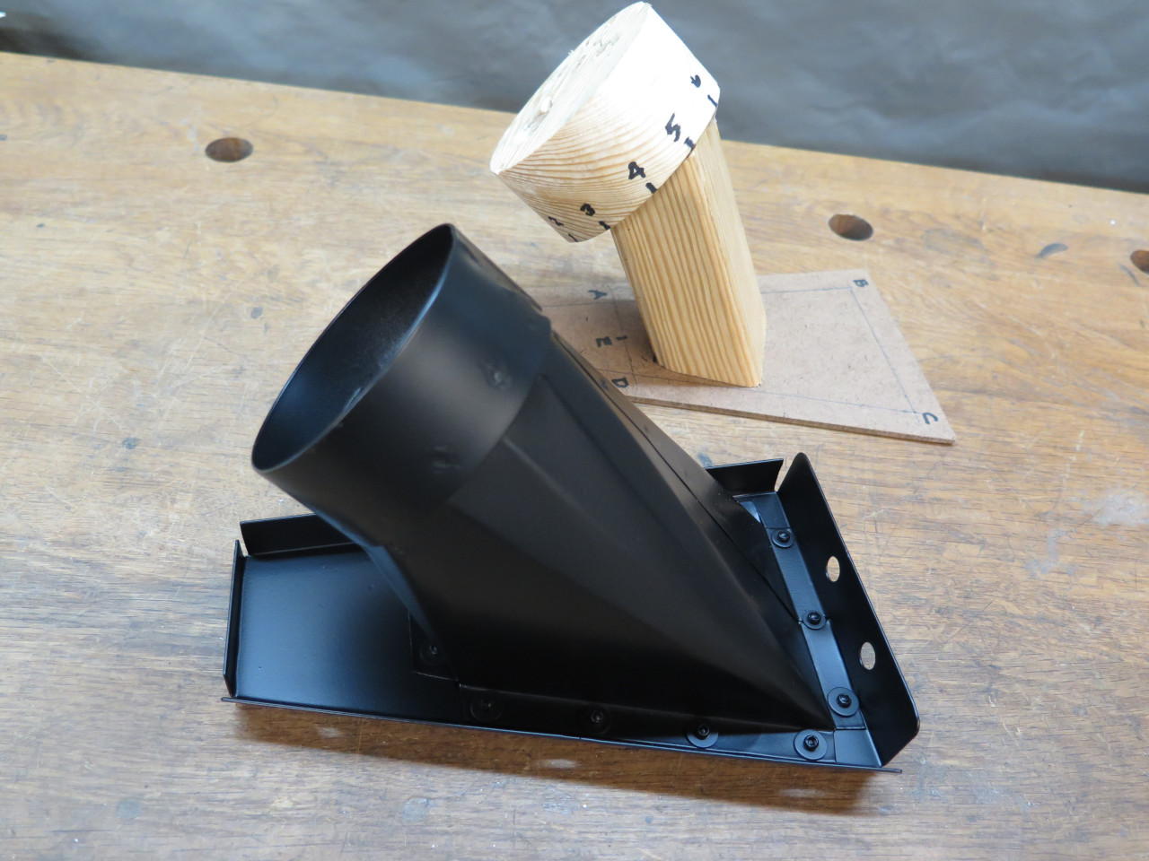
To avoid something hard, I thought of another way that wouldn't require
measuring anything. I tucked a piece of thin hardboard into the
plate, and cut a 3" wooden plug to fit in the end of the duct.
Then, by trial and error, cut a wooden piece with the necessary odd
angles to mate to both of them. Hot glued the three pieces
together, and I had a physical model of how the planes of the two ports
of the transition related to each other.

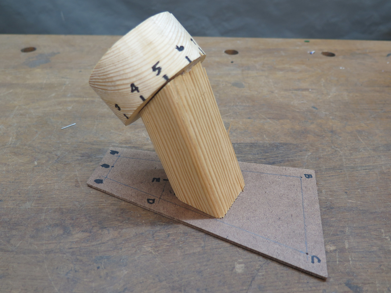
Then, instead of doing it at the drawing board, I could do the layout
directly from the model just using dividers, so no real measuring.
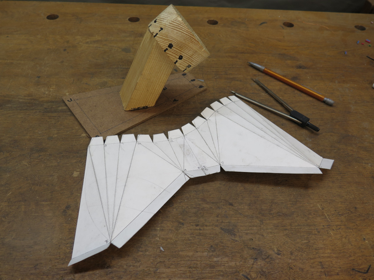

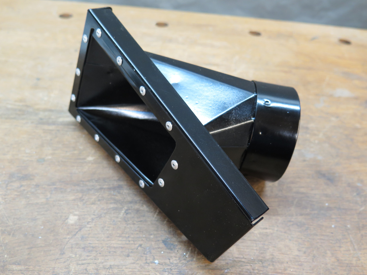
And finally to metal.


These parts were small enough to powder coat. Then a nice top coat after riveting the parts together.
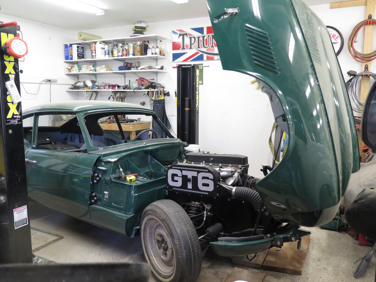
Then took her home. Just need to bridge that gap.
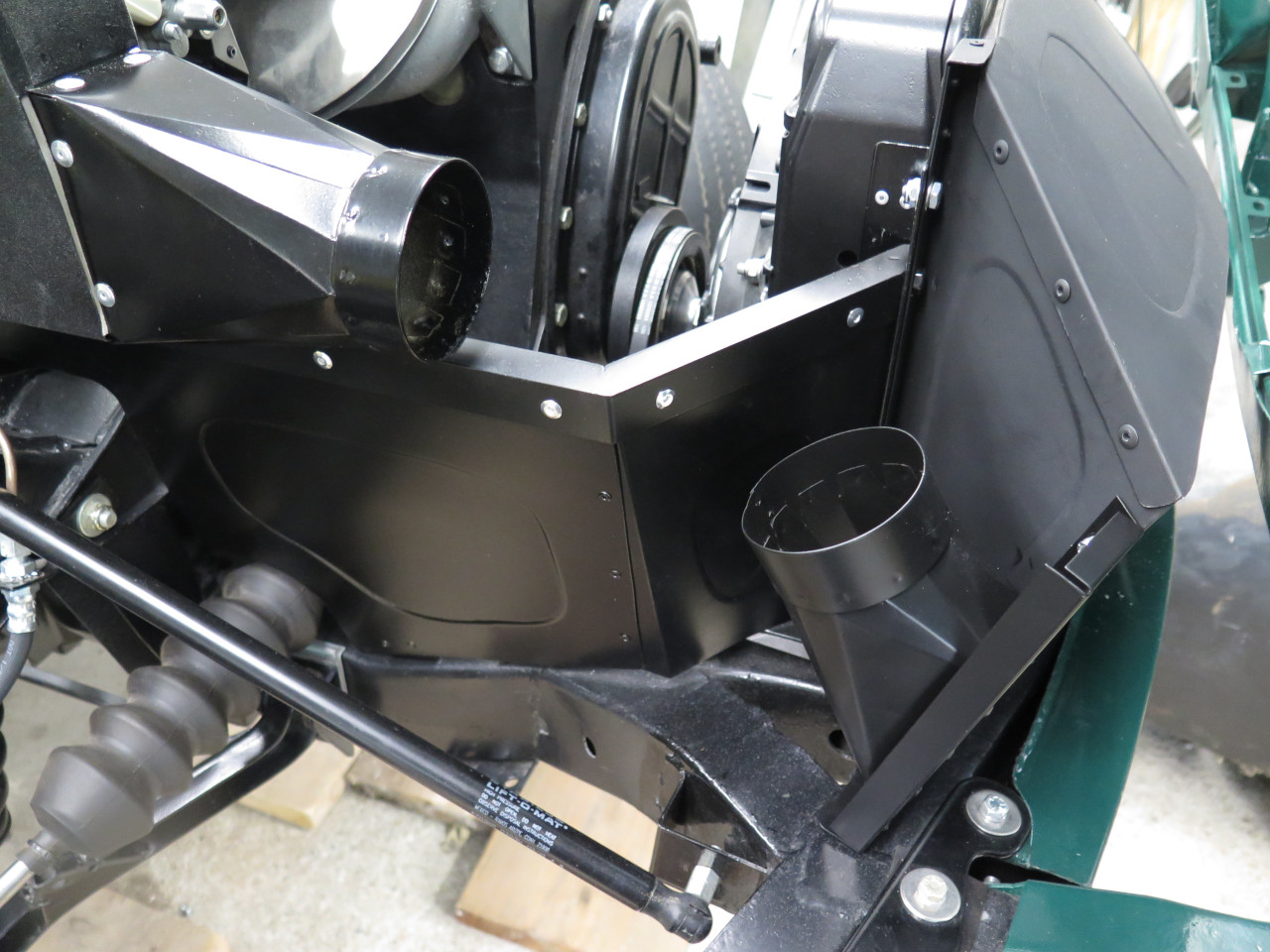
All done:

The duct just clears the top valance rail.
The view no one will see.
This project was a bit of a rabbit hole, but it was challenging
fun. It took a couple of weeks off and on. Cost was mainly
for the filters at around $70.
UPDATE November 22, 2022
A month or two ago, when I posted the above article, there was included
in the comments a mention of a "velocity stack". A velocity stack
is an attachment that can be placed on the mouth of a carburetor to do a
couple of things.
It can "tune" the air inlet by adding a specific length that enhances
the pulsed air flow, much like a tuned exhaust. It can also smooth
out the transition of flow from free air into a constrained
"pipe". The effect has been compared to impedance matching in
electronic circuits. I was aware of the concept, but never really
considered it for this air box. For one thing, velocity stacks are
typically a couple of inches long, so wouldn't really fit in my box.
The comment still peeked my curiosity though, so I looked into it a little more. The commenter offered a link to a 3D print design
he created for CD150 carbs. His design was based on a similar one
for SU HS4 carbs. These designs were "stubby" stacks, less than
an inch high. This likely rules out much of the "tuning" effect,
but it seemed that the flow smoothing could have some benefit.
A little more digging into the HS4 design led to this nice 3-part article.
The article includes results from a series of dyno tests on an MGA
engine, and claims nearly 5% HP gain, and nearly 3% torque gain.
Now, the MGA of course does not use a GT6 engine, but the carbs are
similar enough that I thought it might be a worthwhile project.
I printed one of the stacks to see if I could use it. It turns out
that since the design of my air box is quite a bit different from
stock, I couldn't use it as-is. For one thing, the fasteners for
my box are on the inside of the box, and don't pass through the box and
filters. So the stack would have to accommodate the fastener
heads. It seemed like a fairly simple shape though, so I started
from scratch.
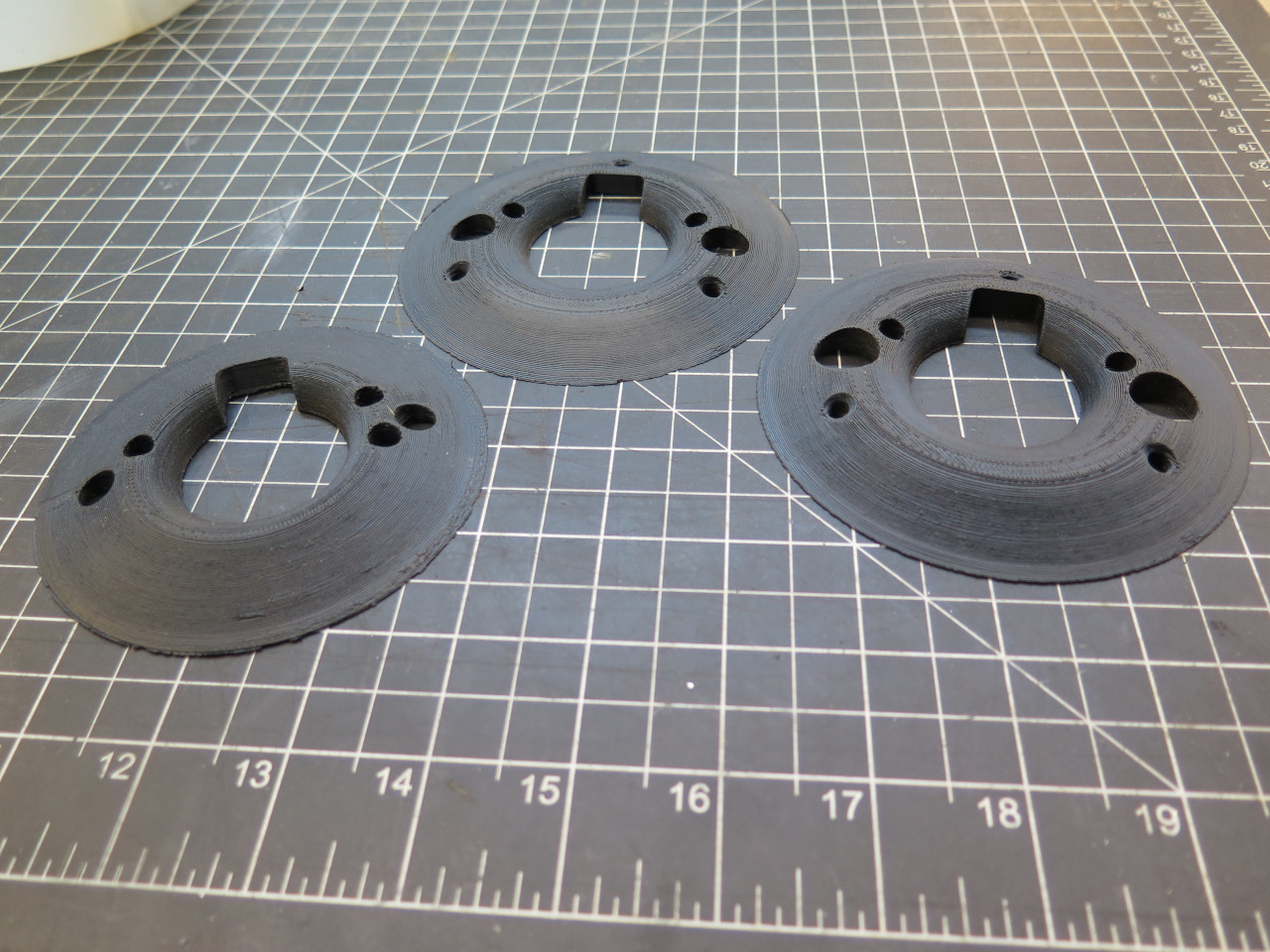
The first thing to determine is what shape to use for the curve.
There are a lot of choices for curves: circular arc, parabola, and
exponential, among others. I ran across a couple of references
that said that an elliptical curve is among the most efficient. So
the cross section of the stack donut is about 3/8 of an ellipse, and a
straight tangent segment to an outer circumference about the same size
as the inside of the filters.

This shape got rotated into a solid torus, then the appropriate cutouts
and holes added. Three of the holes are to attach the stack to the
box.
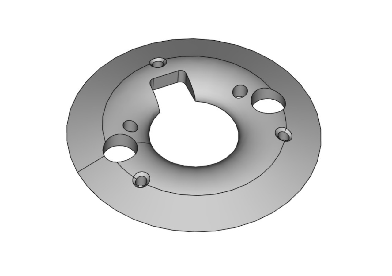
It took a couple of iterations, but here are my stacks (center and right), and the downloaded model.
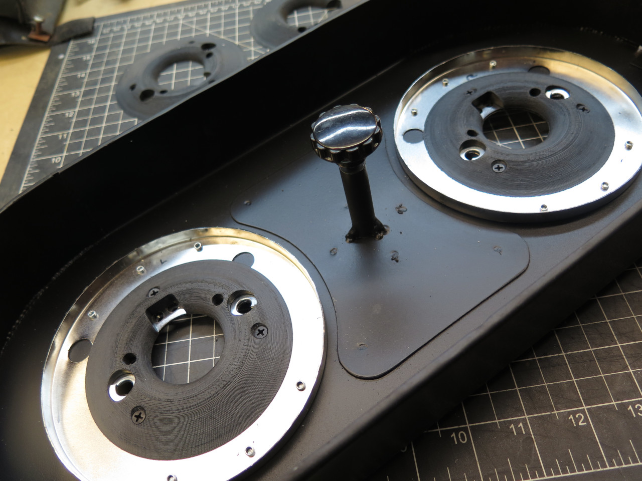
Reality check:
A little surface smoothing and some paint.


Ready to go...
And, installed.
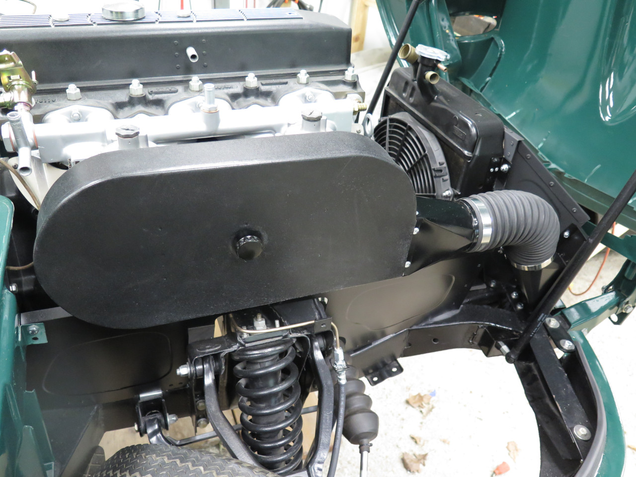
Now, that should have been it for this project. But...
That big expanse of nondescript black metal bothered me. The
original air box at least had some features on it. This one just
seemed like a big blank.
Here's one idea, borrowed from my TR6: A decorative plate for the top of the box that reflects the rocker cover.


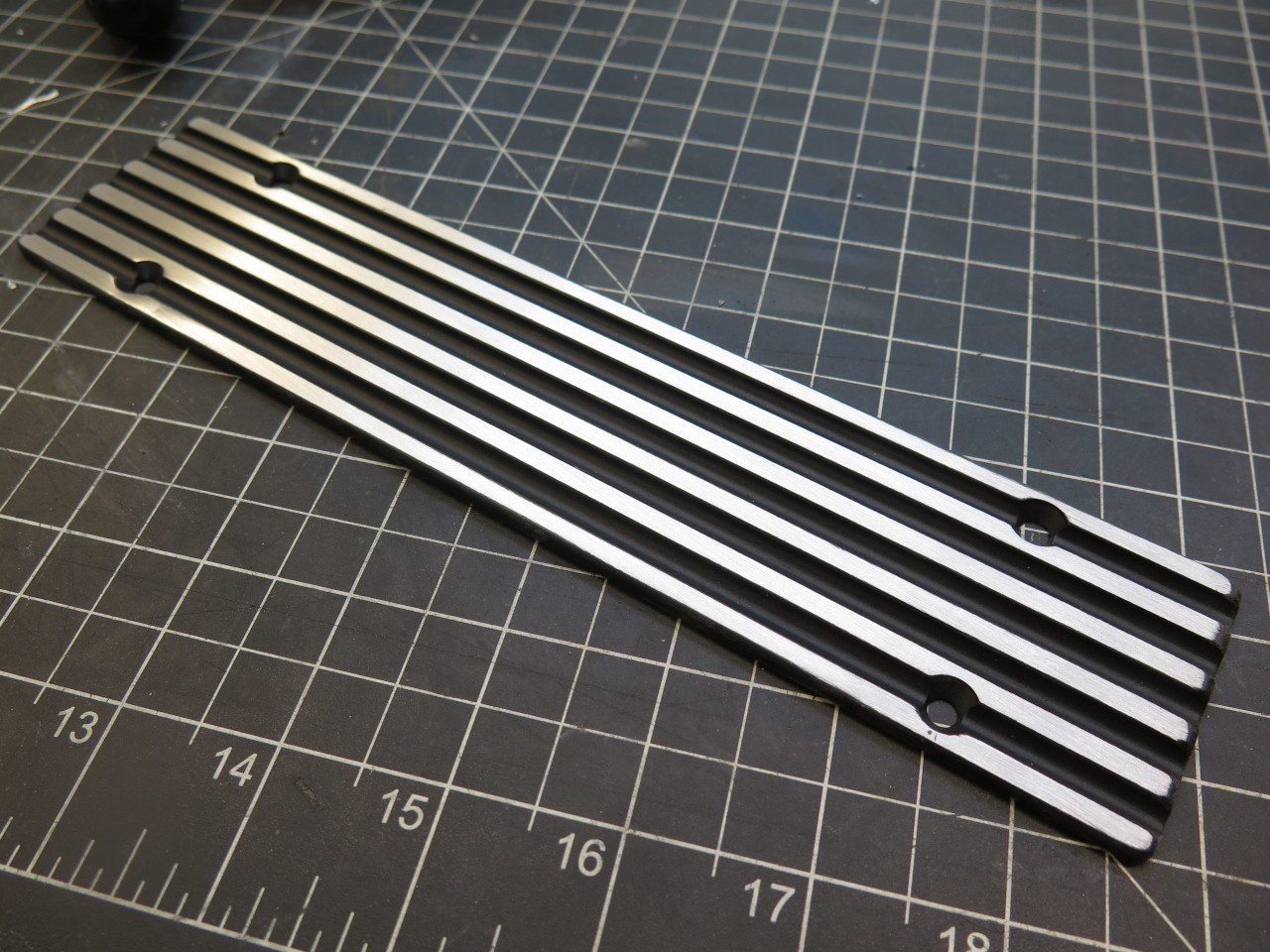

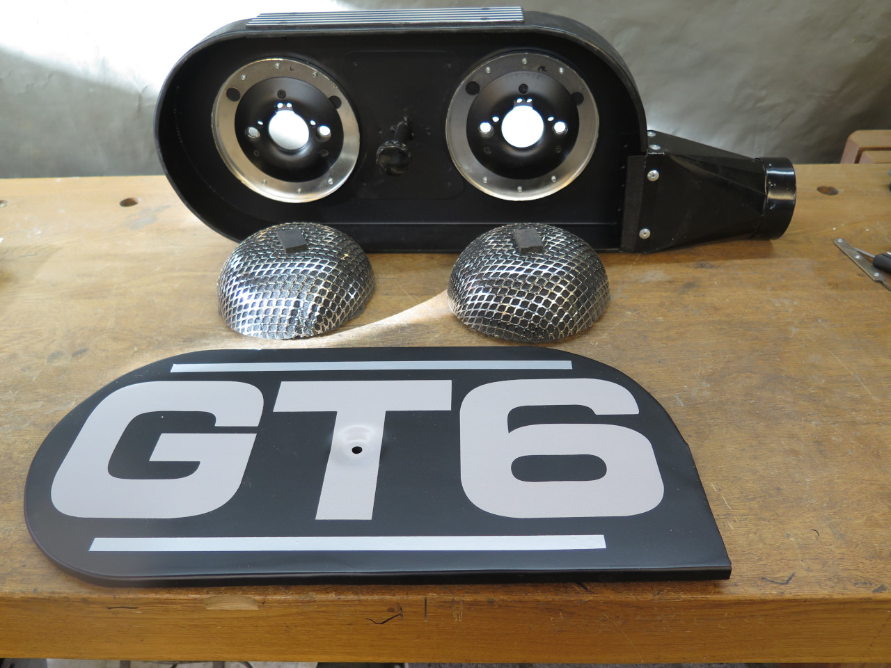
That seems OK, but that wasn't the main problem. I thought maybe
some sort of logo on the box cover might work. I'm generally not a
big fan of logos on cars, and believe that one too few logos on a car
is way better than one too many. Here is where I am right now.
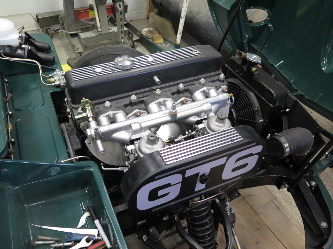
I'm not really sure if I love it. I'll leave it and see if it grows on me.
Comments to ed at elhollin1@yahoo.com
To my other GT6 pages