To my other GT6
pages
December 25, 2020
Steering Column
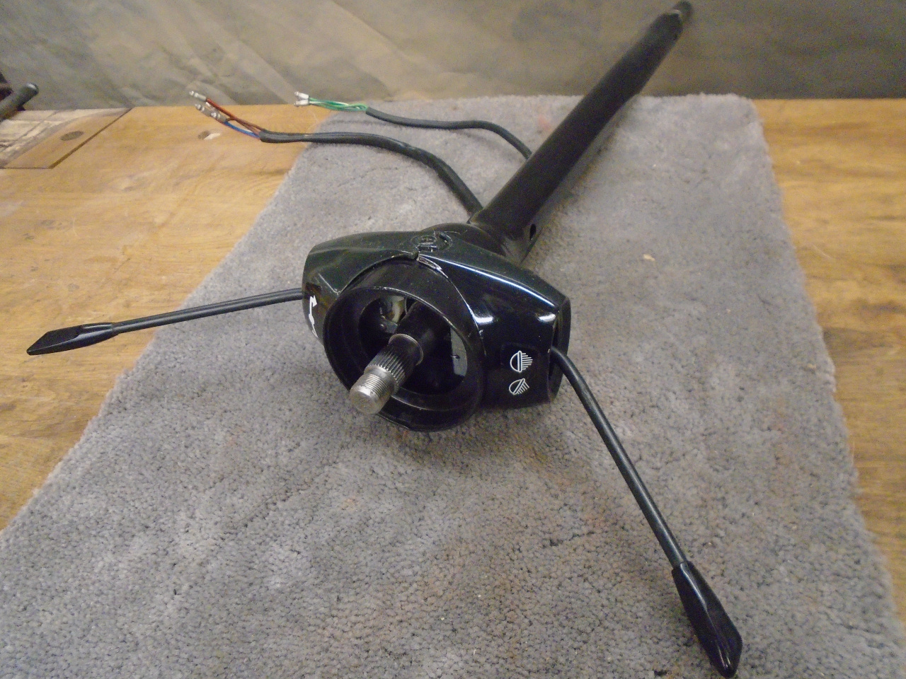
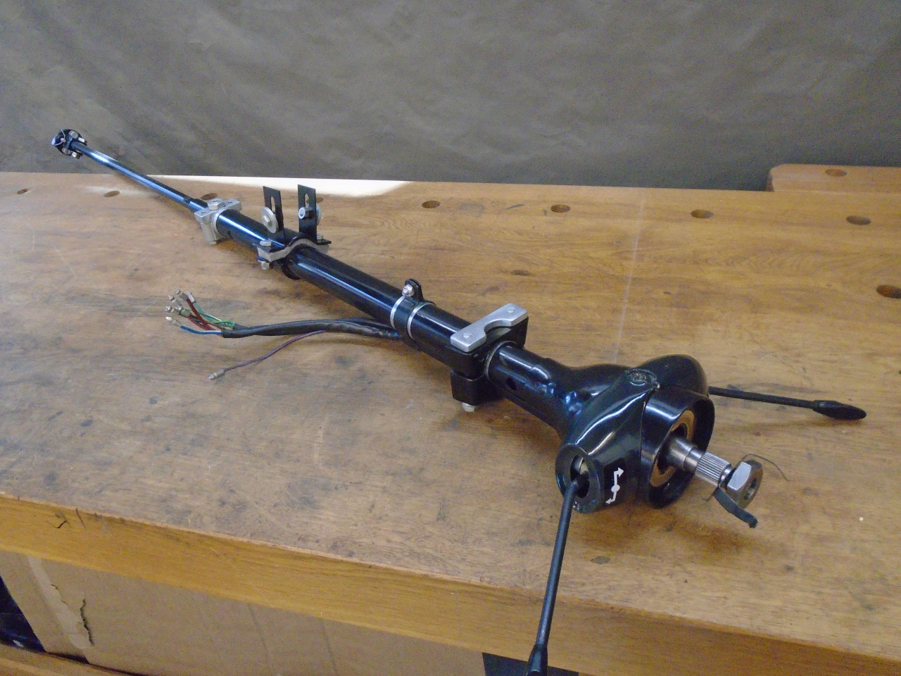
The steering column in the GT6 was apparently used across a range
of both small and large chassis Triumph cars. There seem to be
some mounting variants, and later columns have provision for a
steering lock, but the design is mainly the same. My column
was filthy, tired, and sort of loosey-goosey, but it appeared to
be complete.
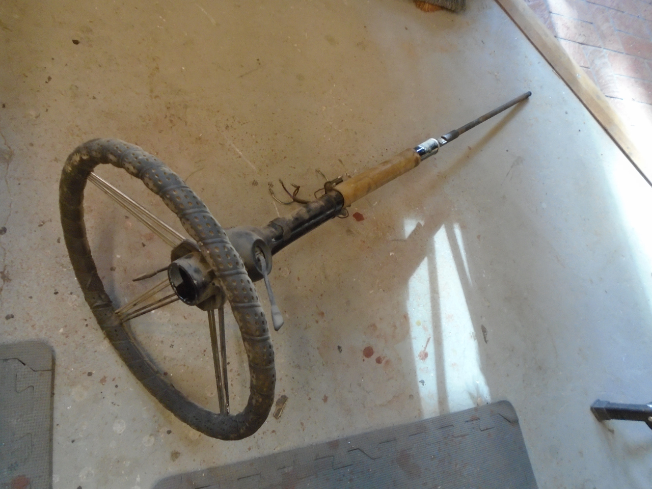
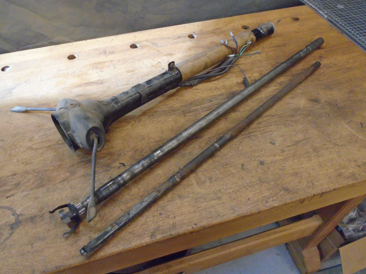
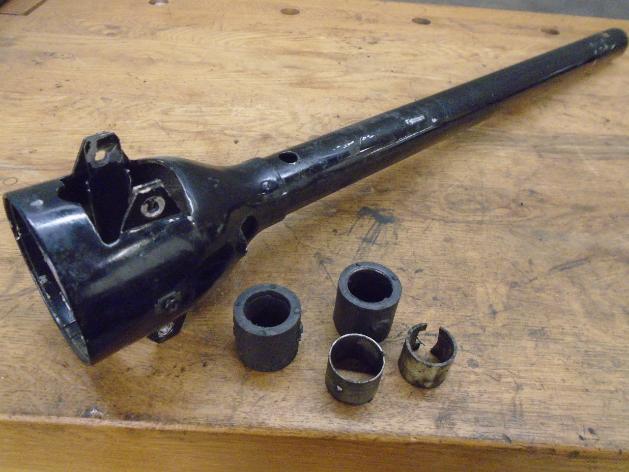
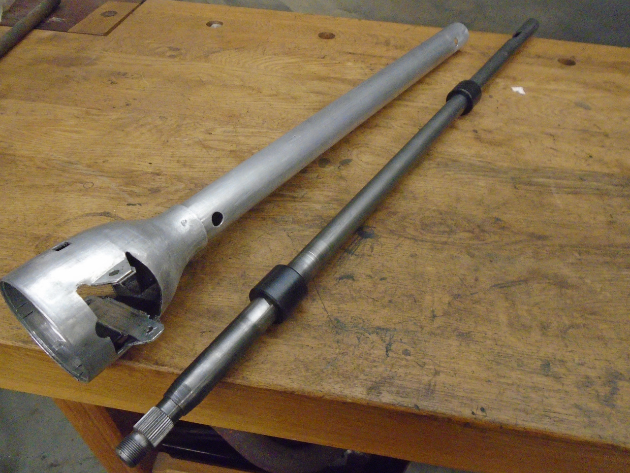
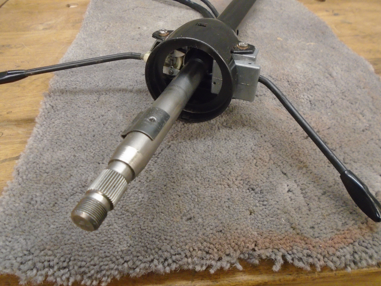
The column is made up of an outer aluminum housing holding a
telescoping shaft. The telescoping shaft consists of the
outer shaft, which is connected to the steering wheel, and an
inner shaft, which connects to the rack and pinion box. The
two shafts are held in relative position by a friction fitting. I
believe the idea is that in a front end collision, the inner shaft
would slide rearward against the friction, absorbing some of the
impact energy. This is only good for a few inches of travel,
though. After that, it appears that another part of the
energy would be taken by crumpling the thin, soft aluminum
housing. This was Triumph's version of the collapsible
steering column.
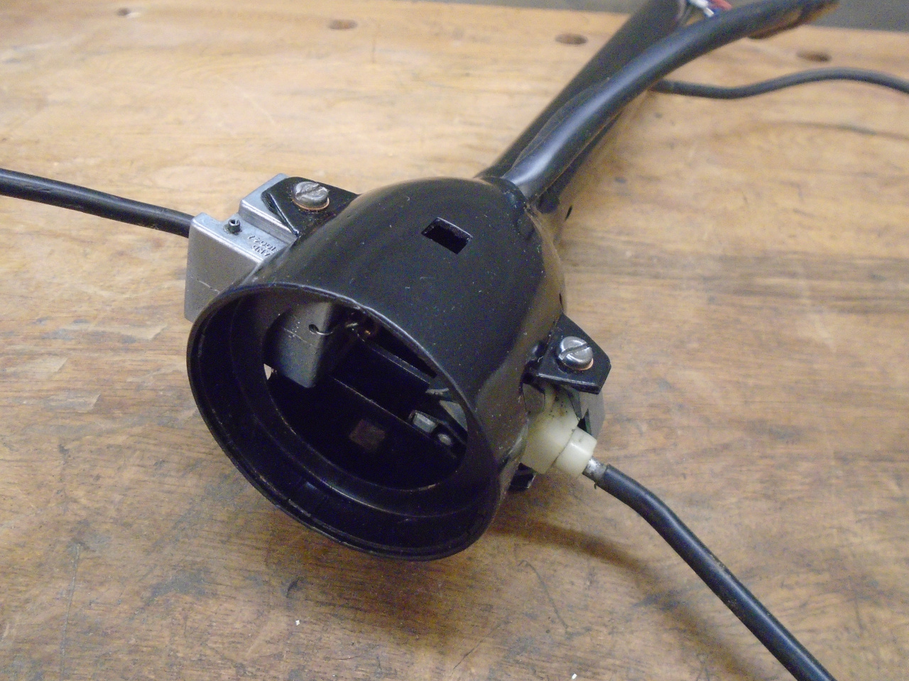
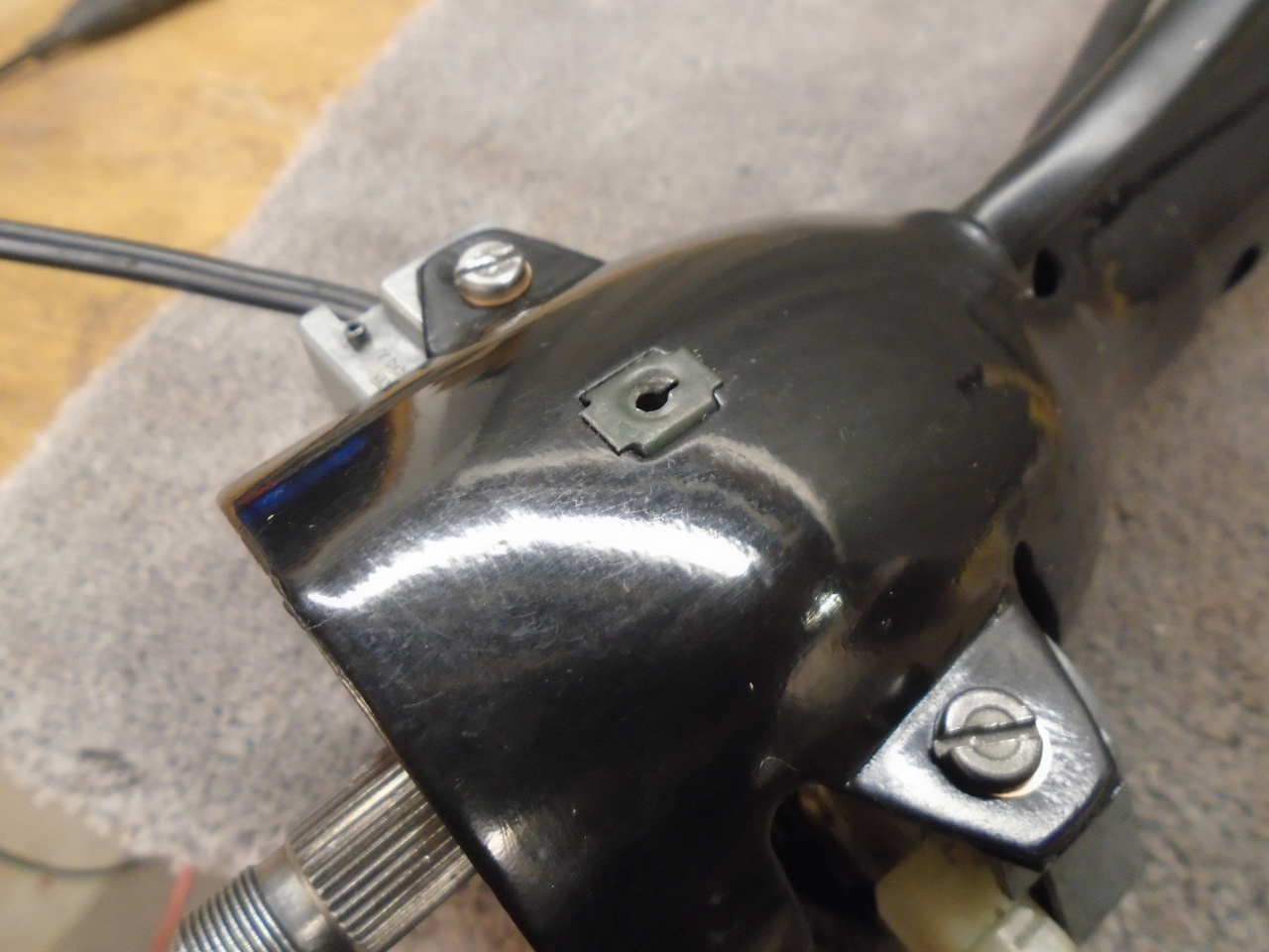
The outer column housing carries the column controls--turn
signals, headlight hi/lo beam, and the horn button parts.
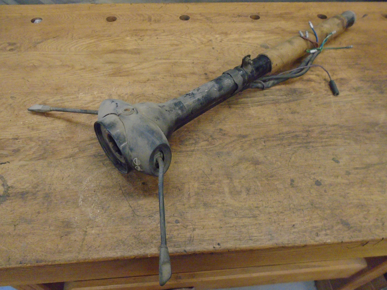
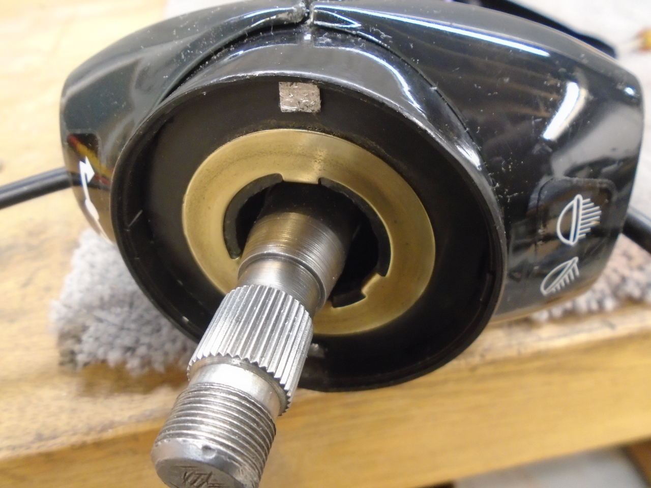
Also inside the column housing are a pair of bushes that the shaft
rides in. Judging from the play in my steering wheel, I knew
the bushes were worn. So, out they came. The original
bushes are a steel cylinder inside a rubber jacket. Inside
the steel is a nylon lining , which is the actual bearing
surface. The rubber jacket has a small protrusions that fit
into holes in the column housing. It can be a bit of a wrestling
match to get the resilient bushes to move. Cutting or
drilling away the rubber protrusions seems to help.
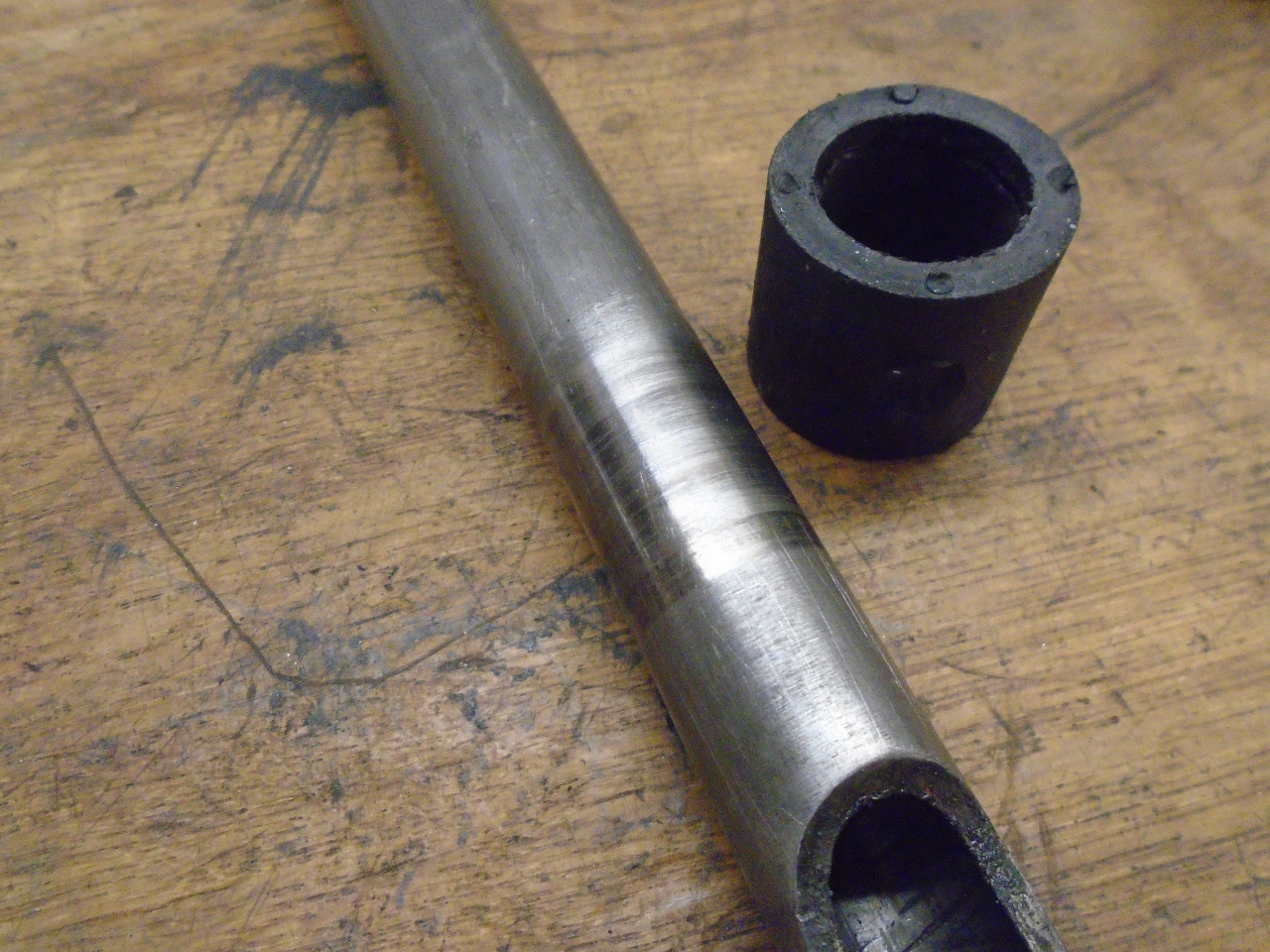
In addition to wear of the nylon insert, my shaft showed signs of
wear. I could see it, feel it, and measure it.
New factory type bushes can be bought, and they probably aren't
that expensive. On the other hand, I didn't really see the
advantage of the multi-layered bushes. A simple solid
bushing, made to press fit in the housing should do the job, and
maybe even tighten up the steering a bit by eliminating the
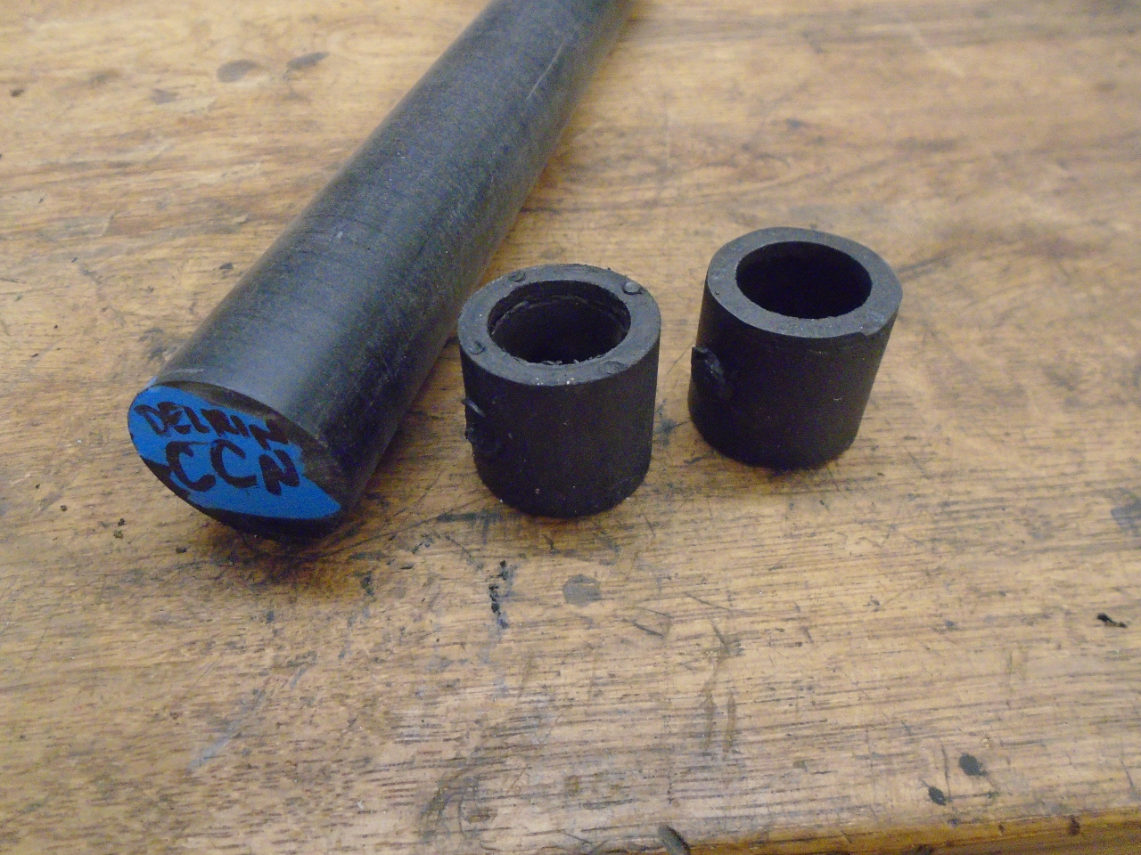
resilient rubber layer. I chose to stick to plastic for the
bearing surface, though. This is a rod of Delrin, an acetal
plastic with good stiffness, good dimensional stability, and high
natural lubricity with steel. The bushes shown are the
originals.
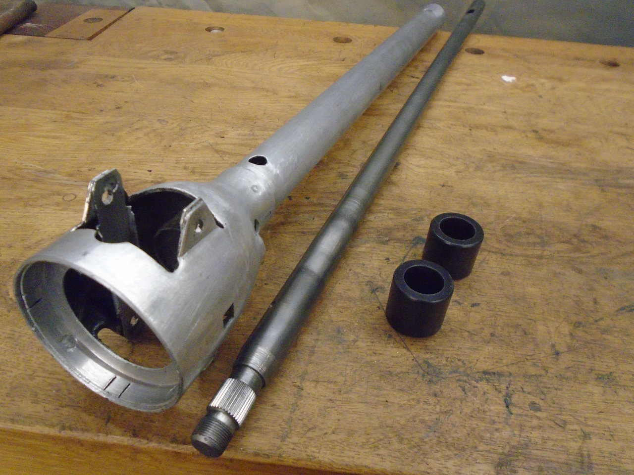
The Delrin bushes were machined for a pretty tight fit in the
housing. The fit was such that I didn't see any need for
locating devices like the nubs on the originals. They are a
nice slip fit on the shaft.
There is some leeway in exactly where the bushes go in the
housing. I took advantage of that and put the bushes a
little farther apart than stock. The main reason I did this
is so the bushes don't ride on the areas worn by the original
bushes, but I think the slightly wider spacing may also improve
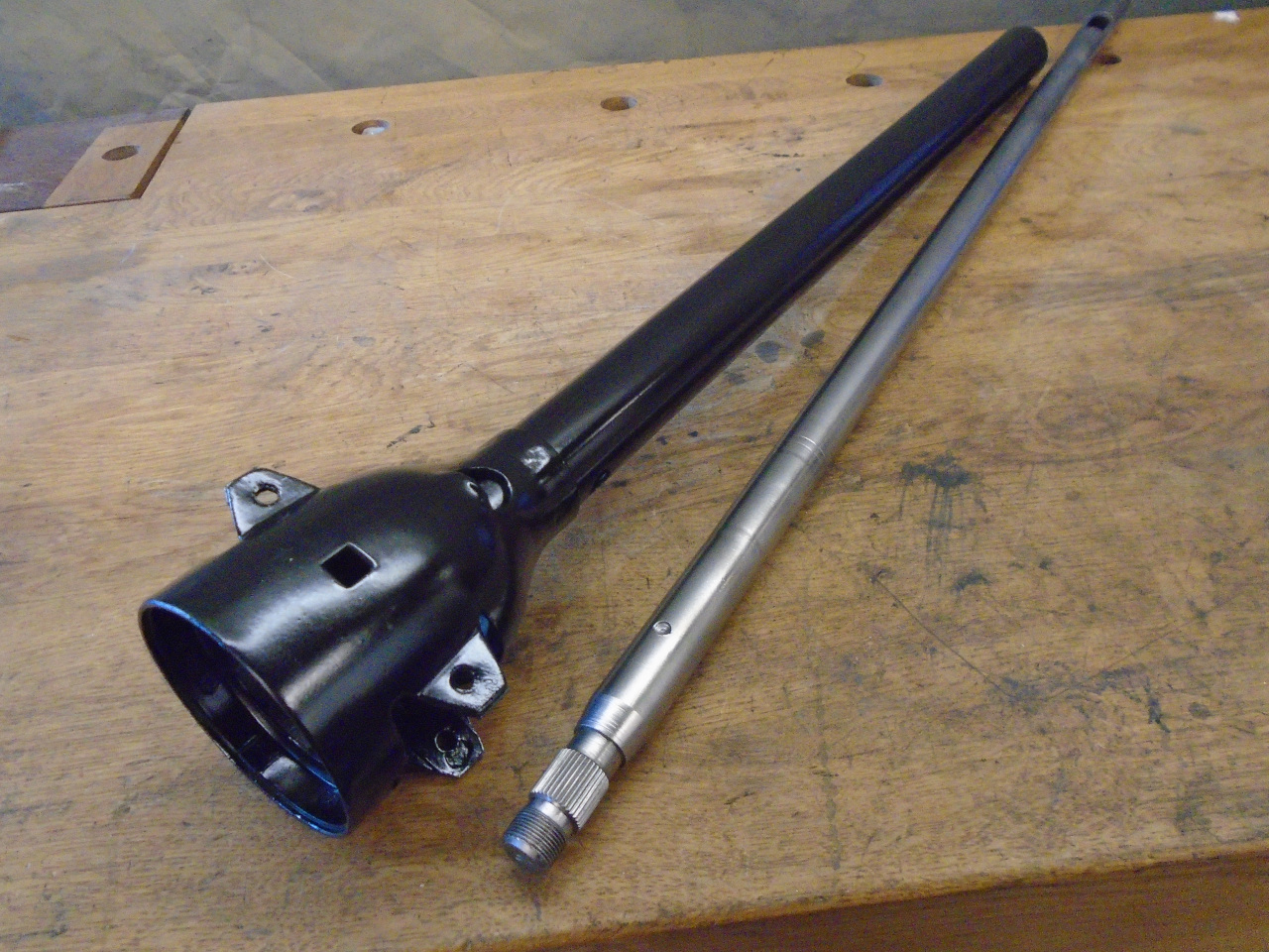
the solid feel of the steering wheel. I powder coated the
housing before installing the bushes. I decided to help the
natural lubrication by squirting in a little graphite powder in
and around the bushes. The result is a very nice tight but
smooth rotation of the shaft in the housing.
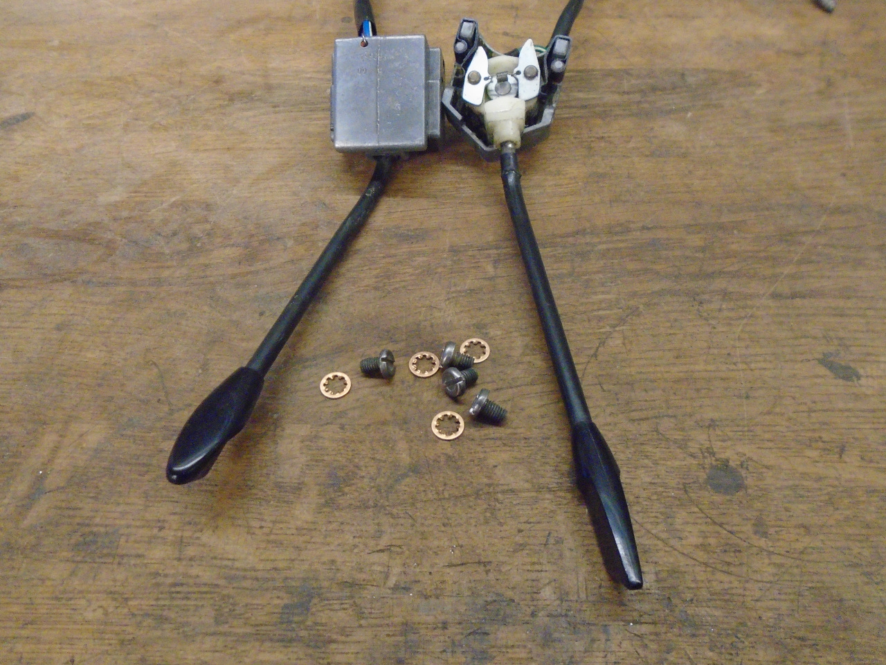
Next out of the tub of steering column parts was the electrical
controls.
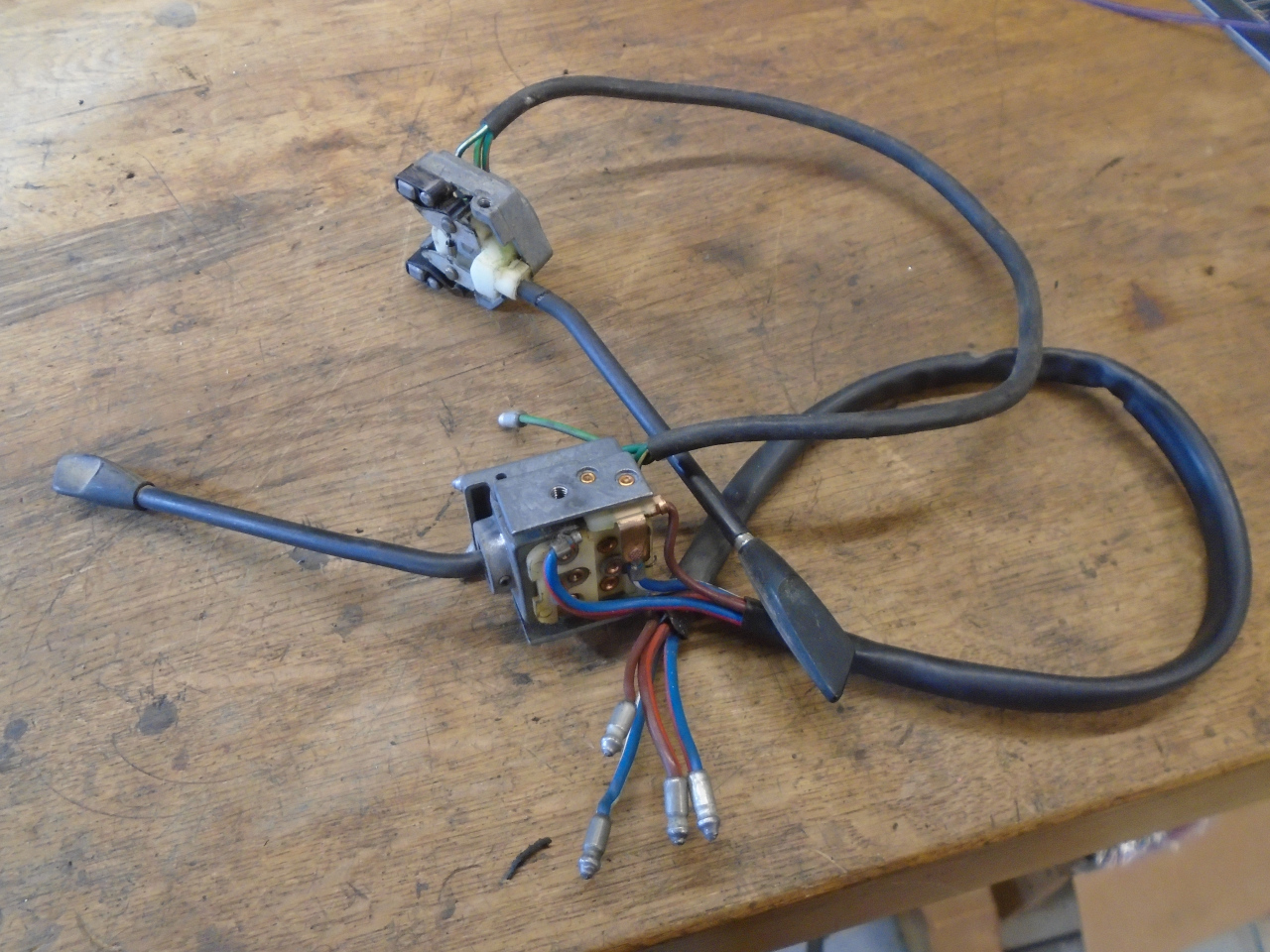
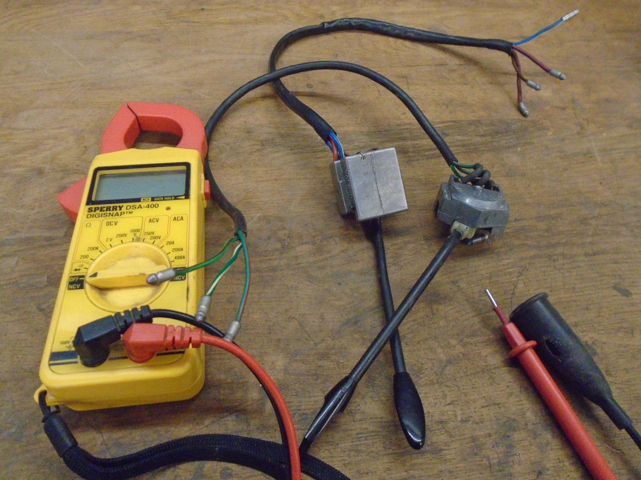
A general cleaning made them look good enough to use, but I wanted
to make sure they worked. All was good except the high beam
circuit. It was frustratingly intermittent, but I couldn't
reproduce it on demand. I thought the problem was at the
bullet terminal end. Replacing the bullet fixed it.
Ready for install. One interesting factoid: the fixing
screws for the controls, which appear to be 8-32 are actually a
rather odd 8-36. Not odd, exactly, since 36 is the standard
UNF pitch for a #8 machine screw, but it's not very common.
I'm sure some well-intentioned folks have jammed an 8-32 in there.
Then I checked the turn signal canceling function. It
depends on this little clip fastened to the upper steering shaft.
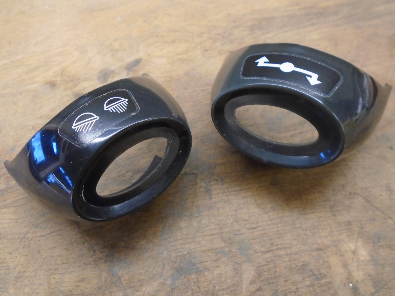
Then it was the escutcheons that cover the switches. They
are just plastic shells that improve he esthetics. The one
on the right was just cleaned up with soap and water.
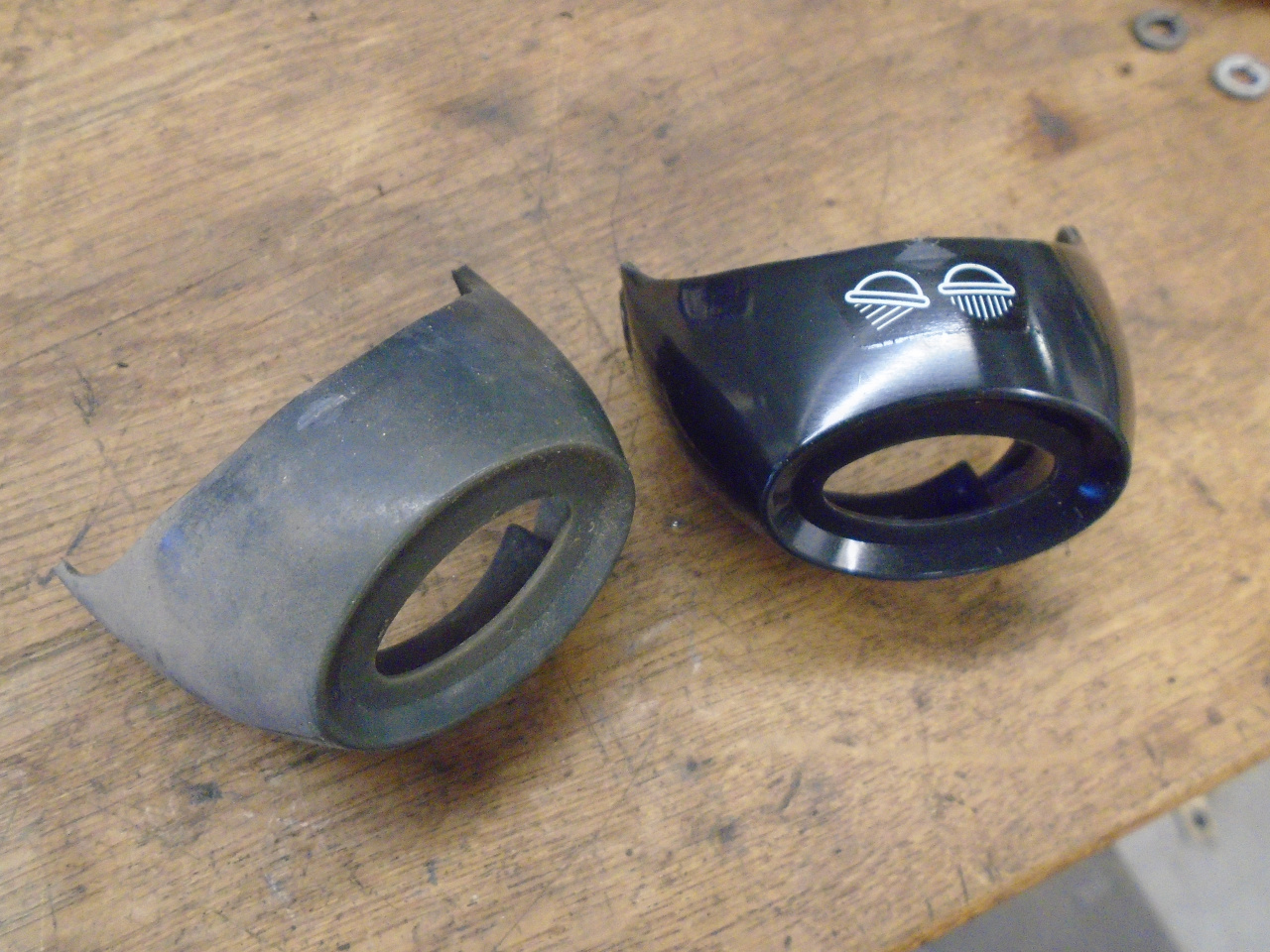
This is probably an example of where I maybe should have left well
enough alone. I thought the white legends on the escutcheons
were a little natty, so I removed them, used some plastic
polishing compound to brighten up the plastic, and applied new
waterslide decals. Frankly, after the work to improve them,
I don't think they look any better, and maybe worse.
Certainly the outline of the decal is more visible than
before. Ah, well. Live and learn.
These little inserts have the threads for the screws that hold the
escutcheons.
The escutcheons were applied...
...and then the horn contact ring goes in so its wire can
join the others. A couple of tabs in the housing bend down
to hold it in.
This little piece is a cover to protect the wires as they come out
of the column housing.
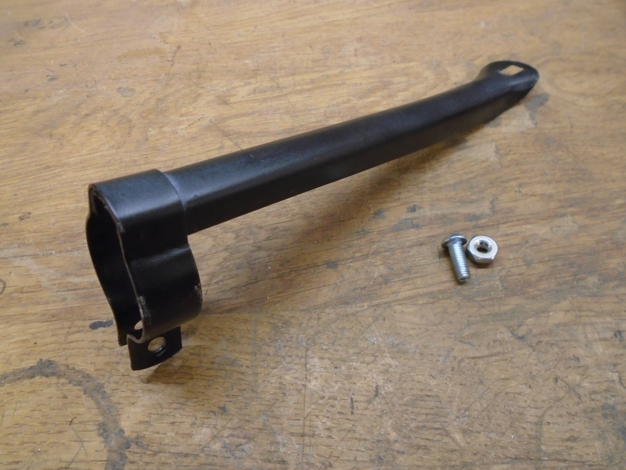
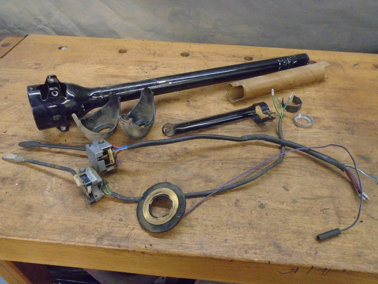
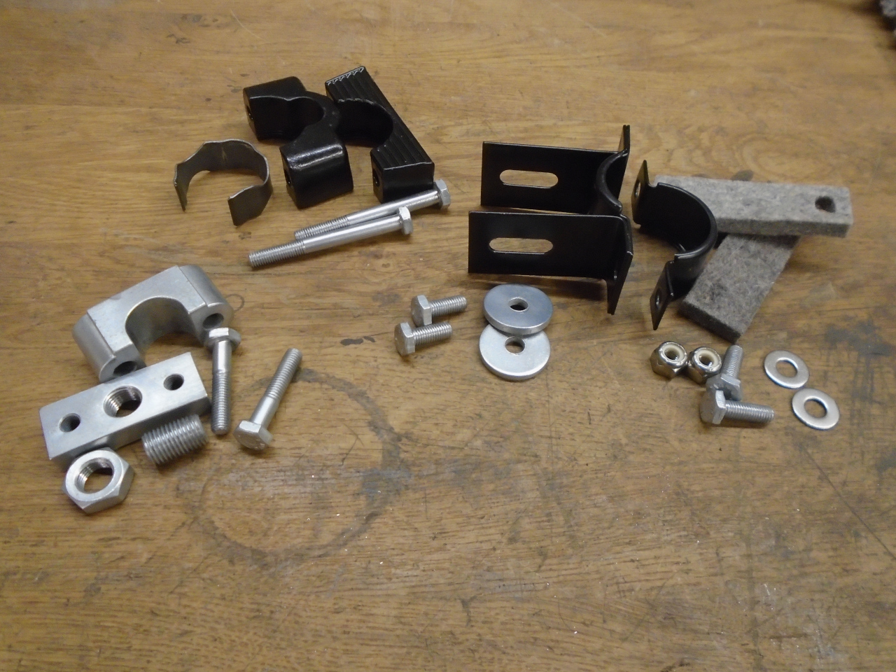
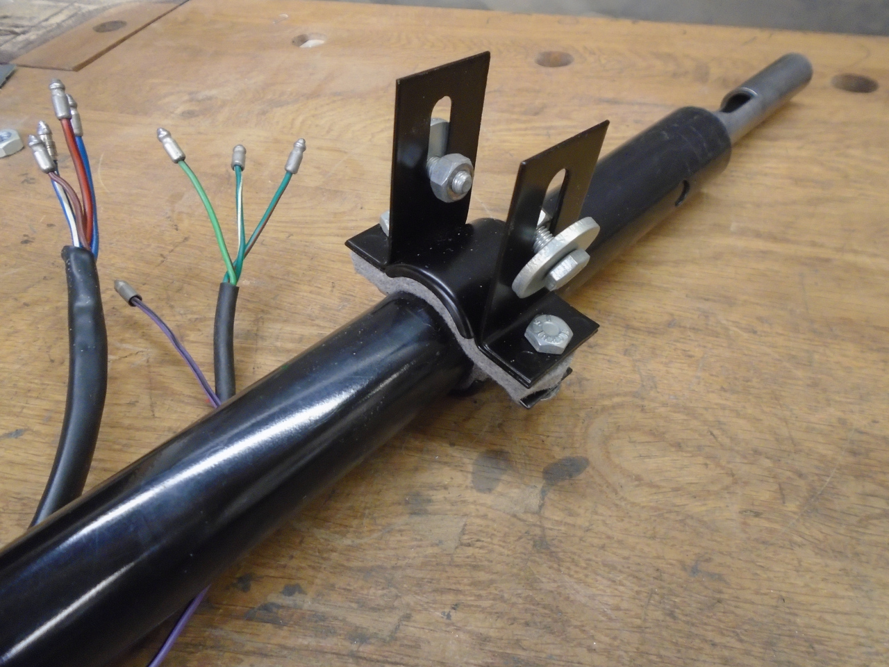
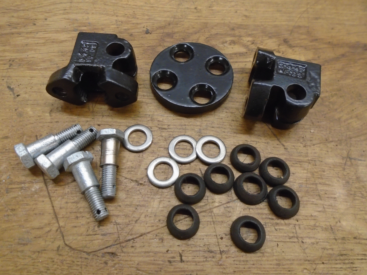
Then it was time for some mounting brackets. The parts at
the top are for the rear mount (closest to the steering wheel),
while the parts at the right are for the frontmost mount. The
black parts are powder coated, the silver parts are stripped and
replated.
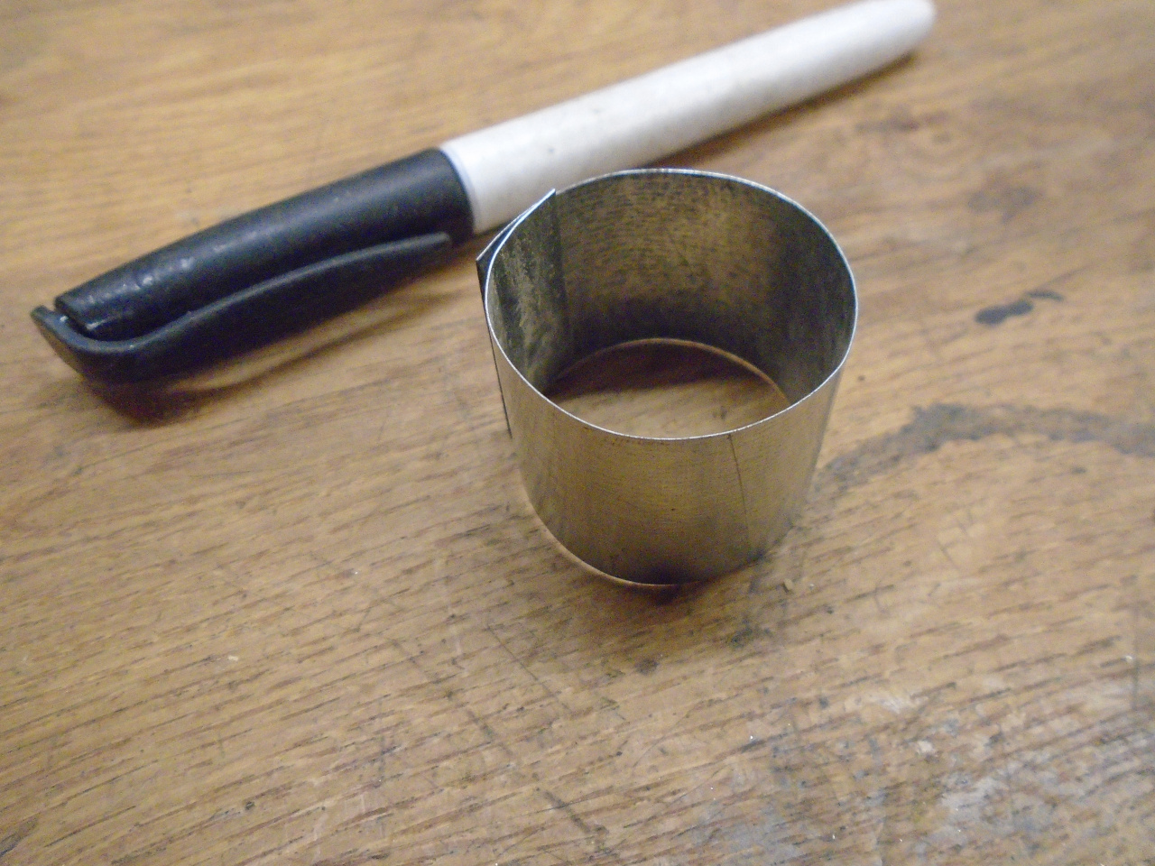
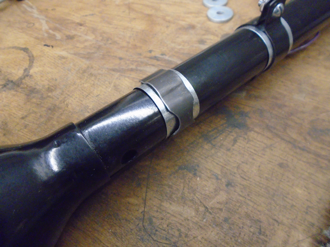
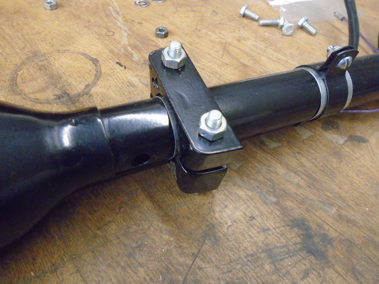
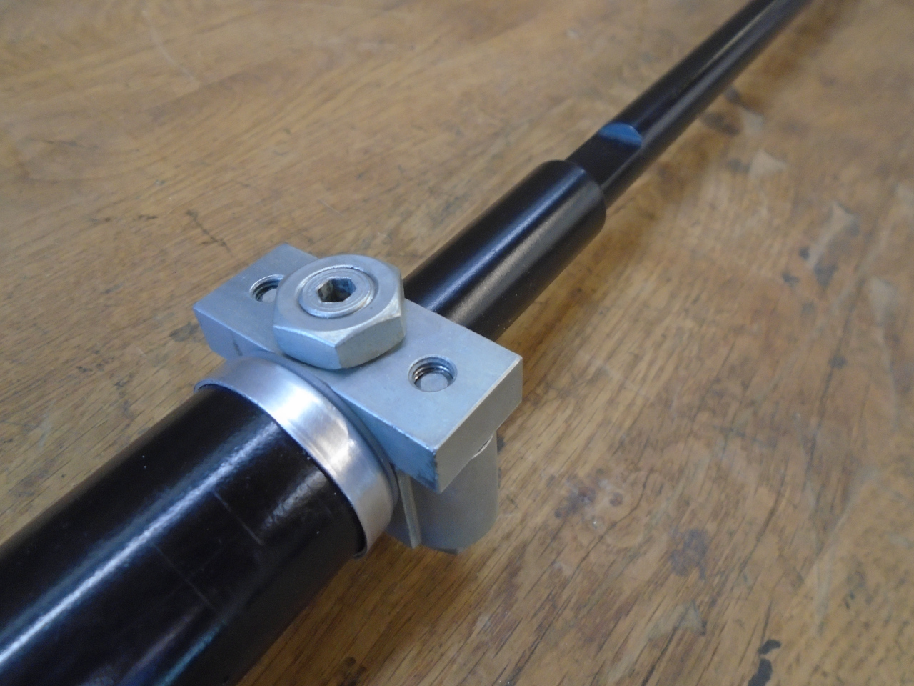
The rear mount has a little clip that snaps around the
housing. Since the aluminum of the housing is so soft, it
gouges very easily. I put little bands of galvanized steel
sheet under that clip and under the band for the wire
protector. The bands protect the aluminum.
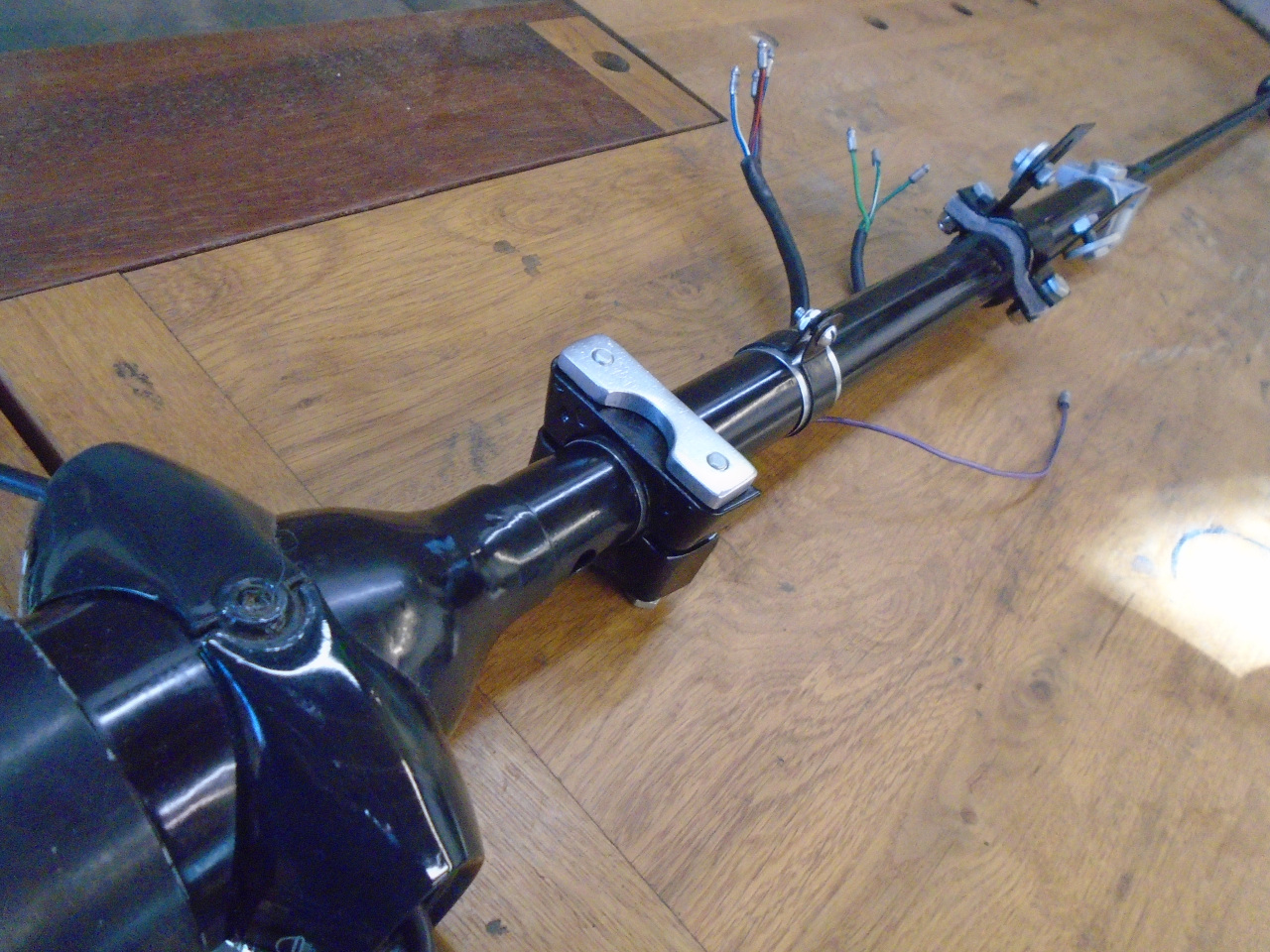
The front bracket gets new felt strips that gently cradle the
column.
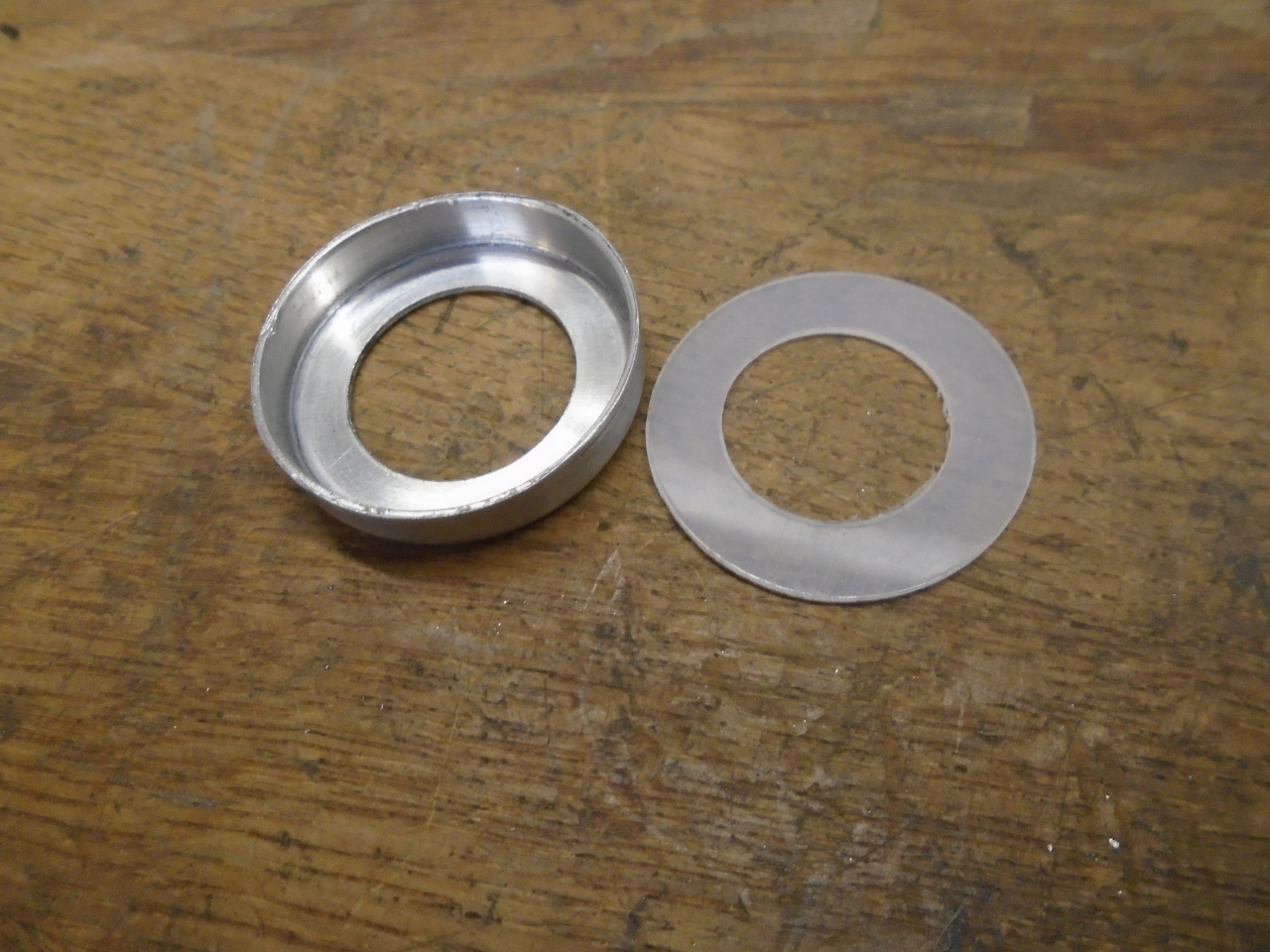
These parts close off the lower end of the column housing.
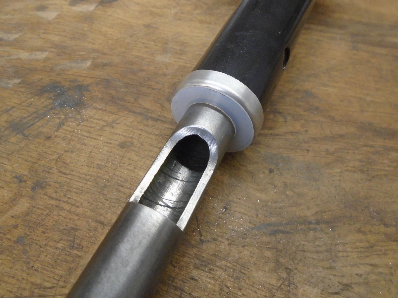
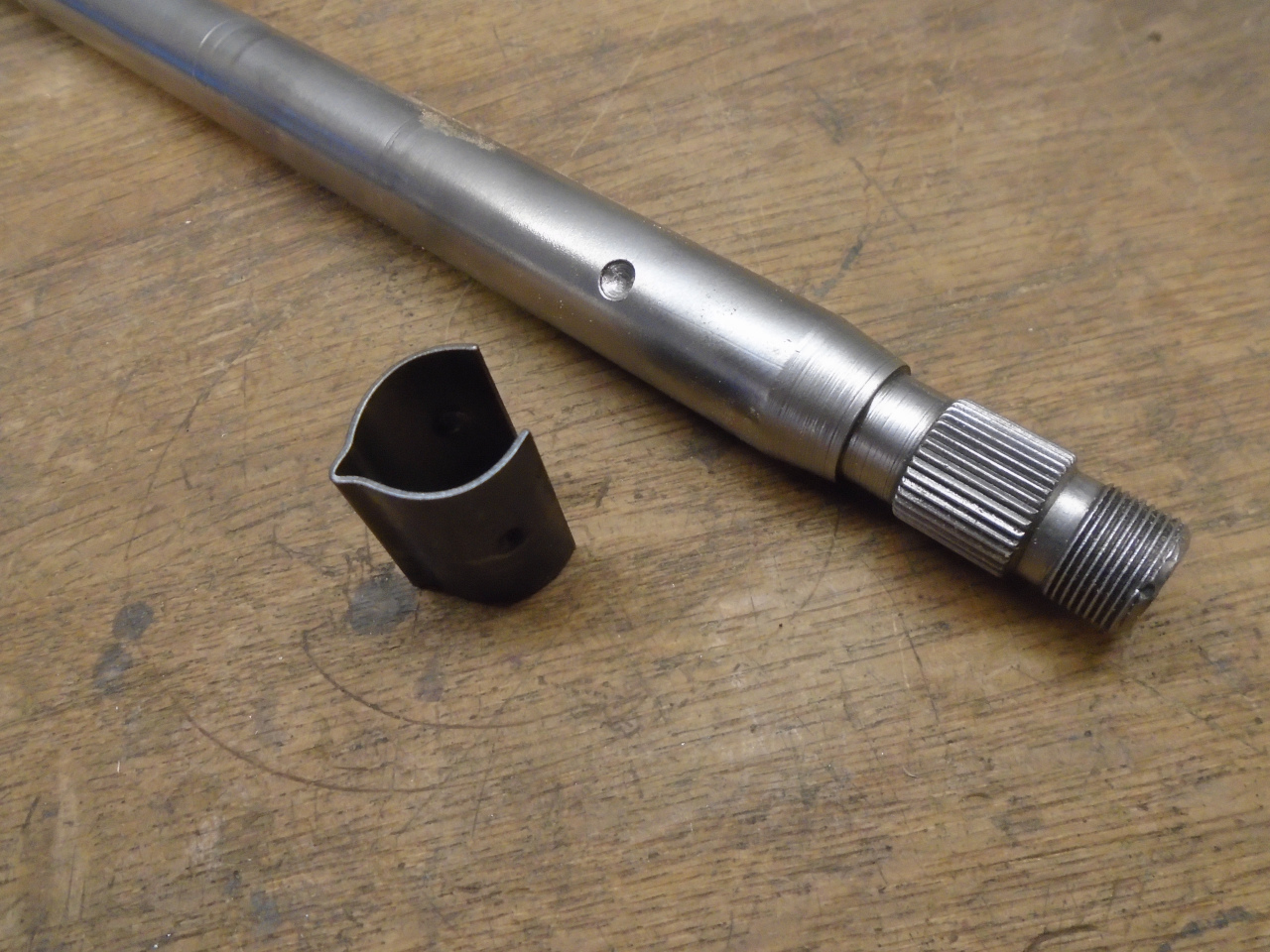
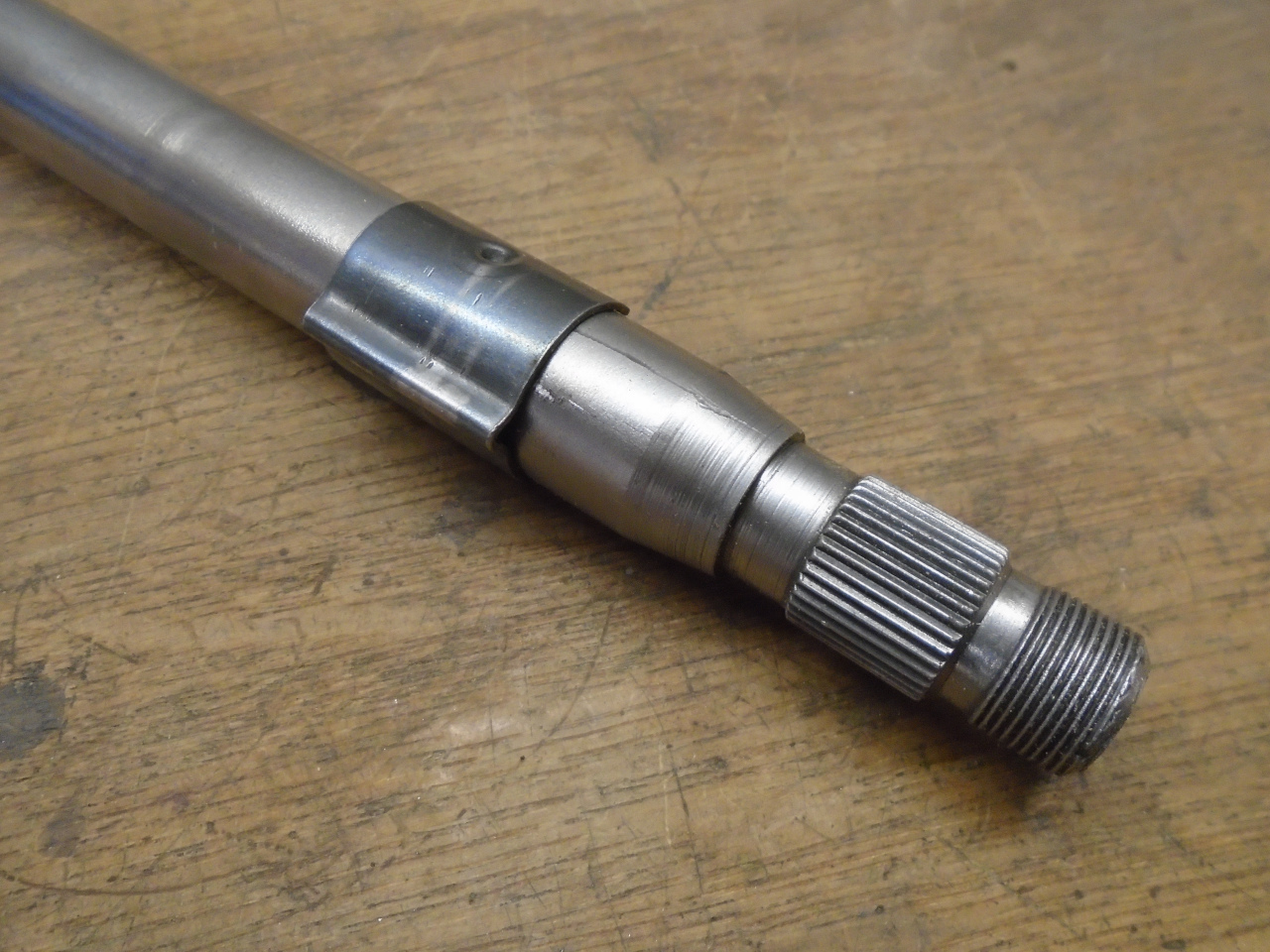
The last thing to do is install the inner (lower) steering shaft.
There is a cutout in the outer shaft that allows the friction
fitting to bear down on a flat on the inner shaft.
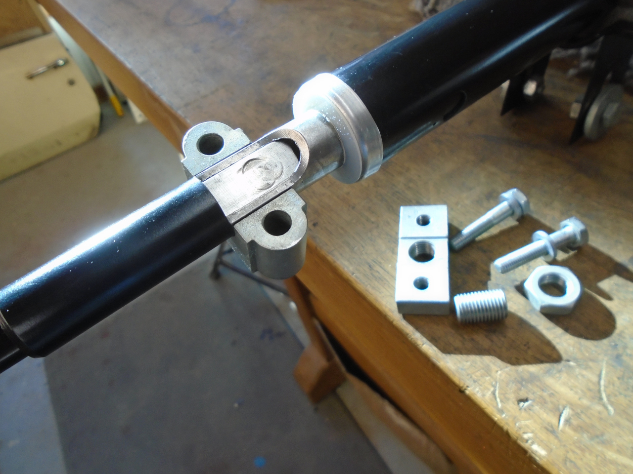
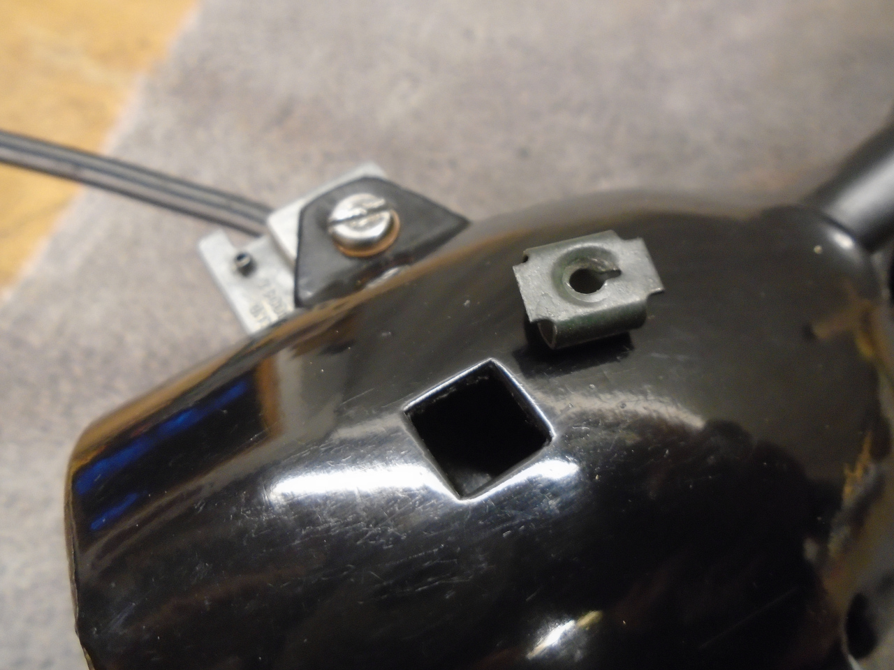
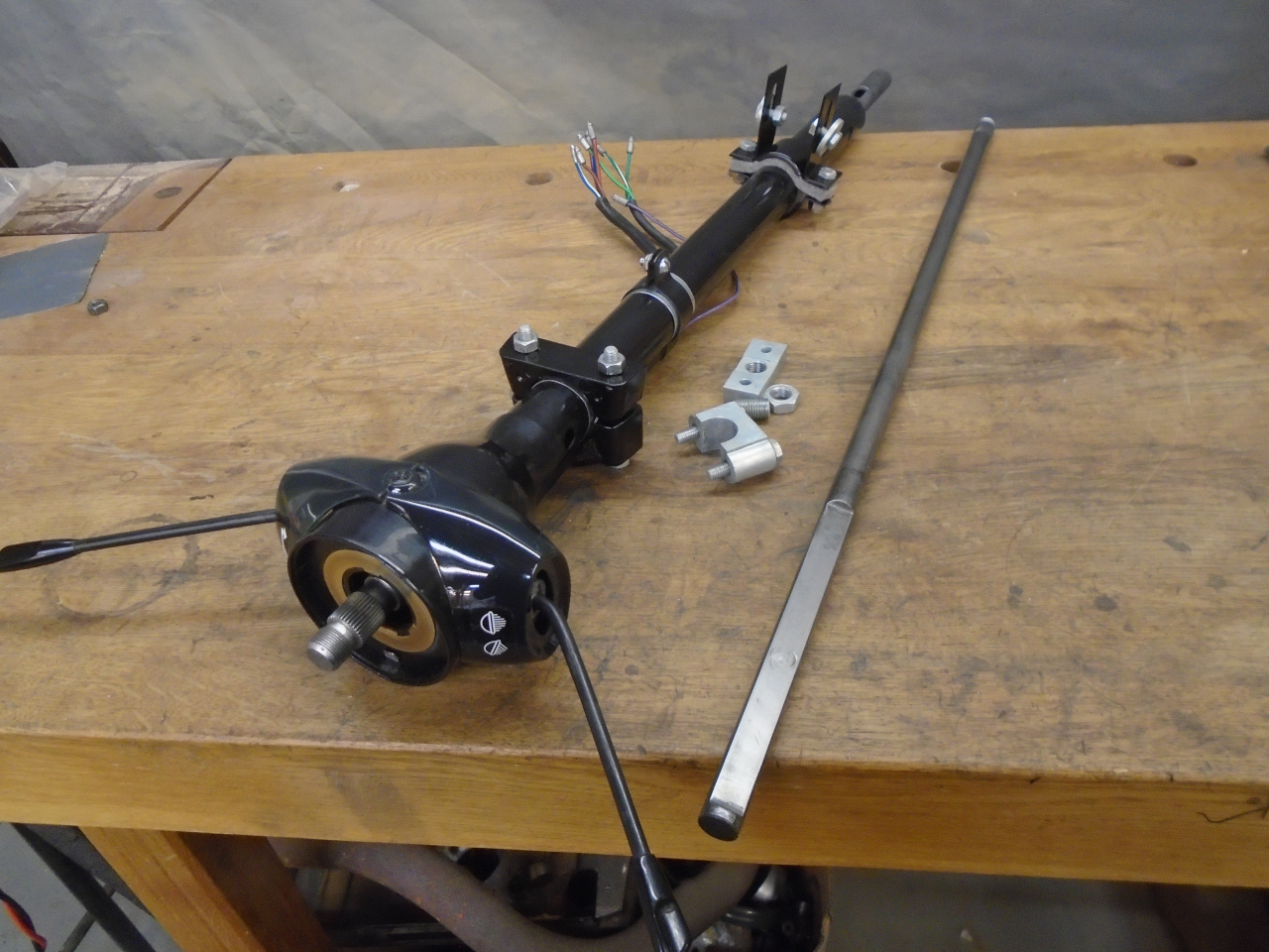
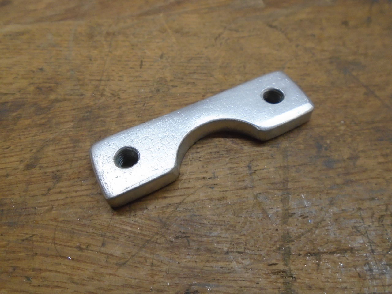
I've been holding on to this mystery part for over a year
now. I finally realized where it goes. It's a nut
plate for the rear column bracket.
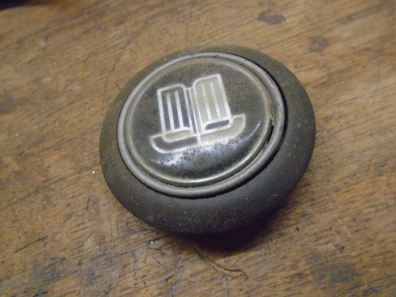
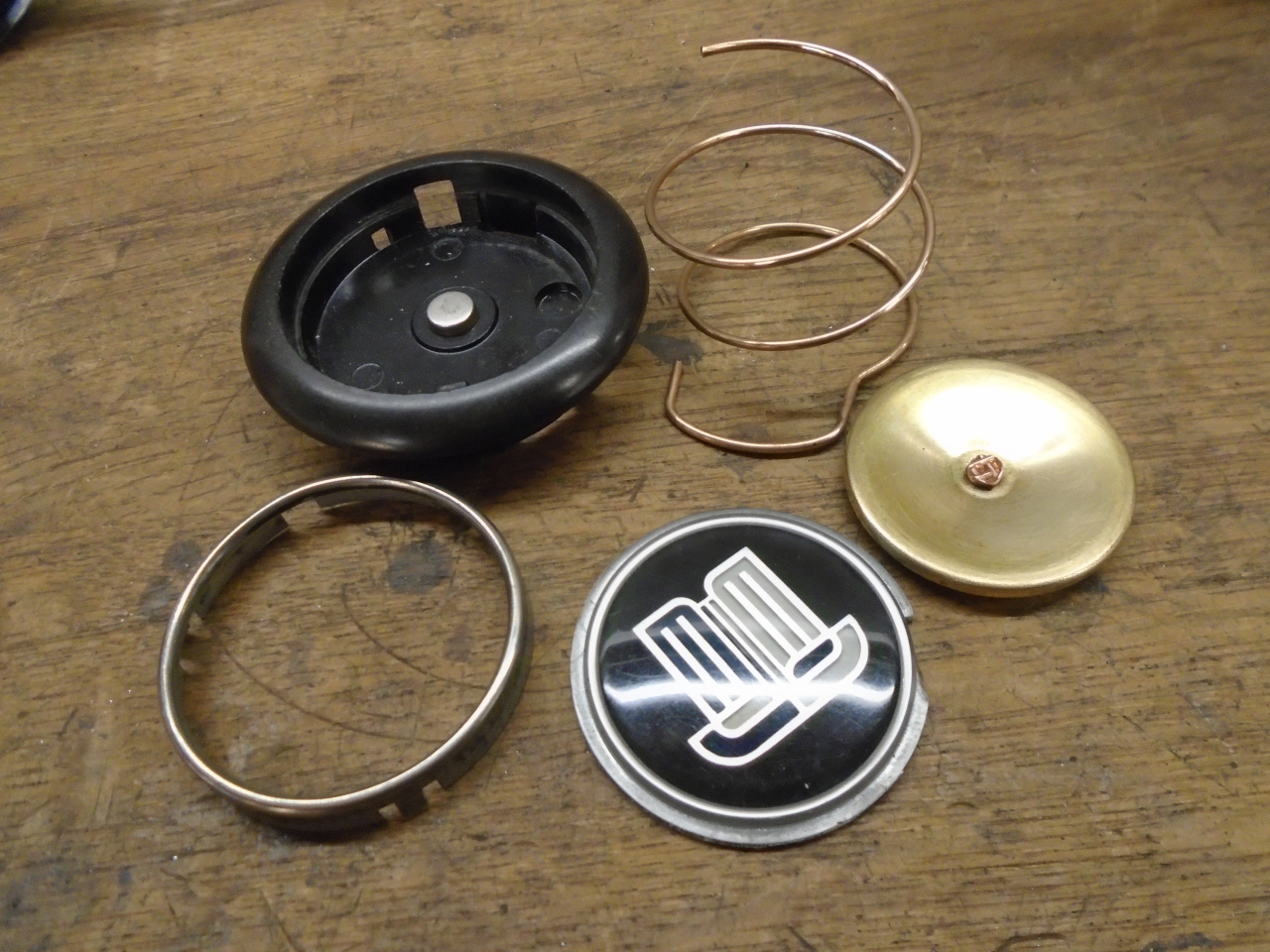
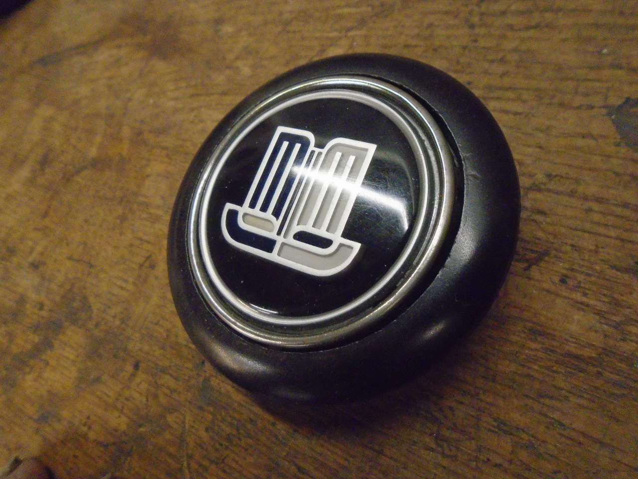
There were a couple of other items in the steering column
bin. The horn button really goes more with the steering
wheel, which I'm not doing right now, but I cleaned it up anyway.
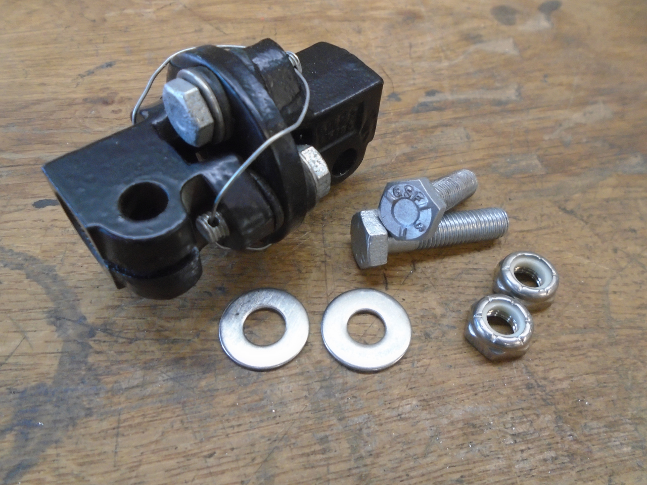
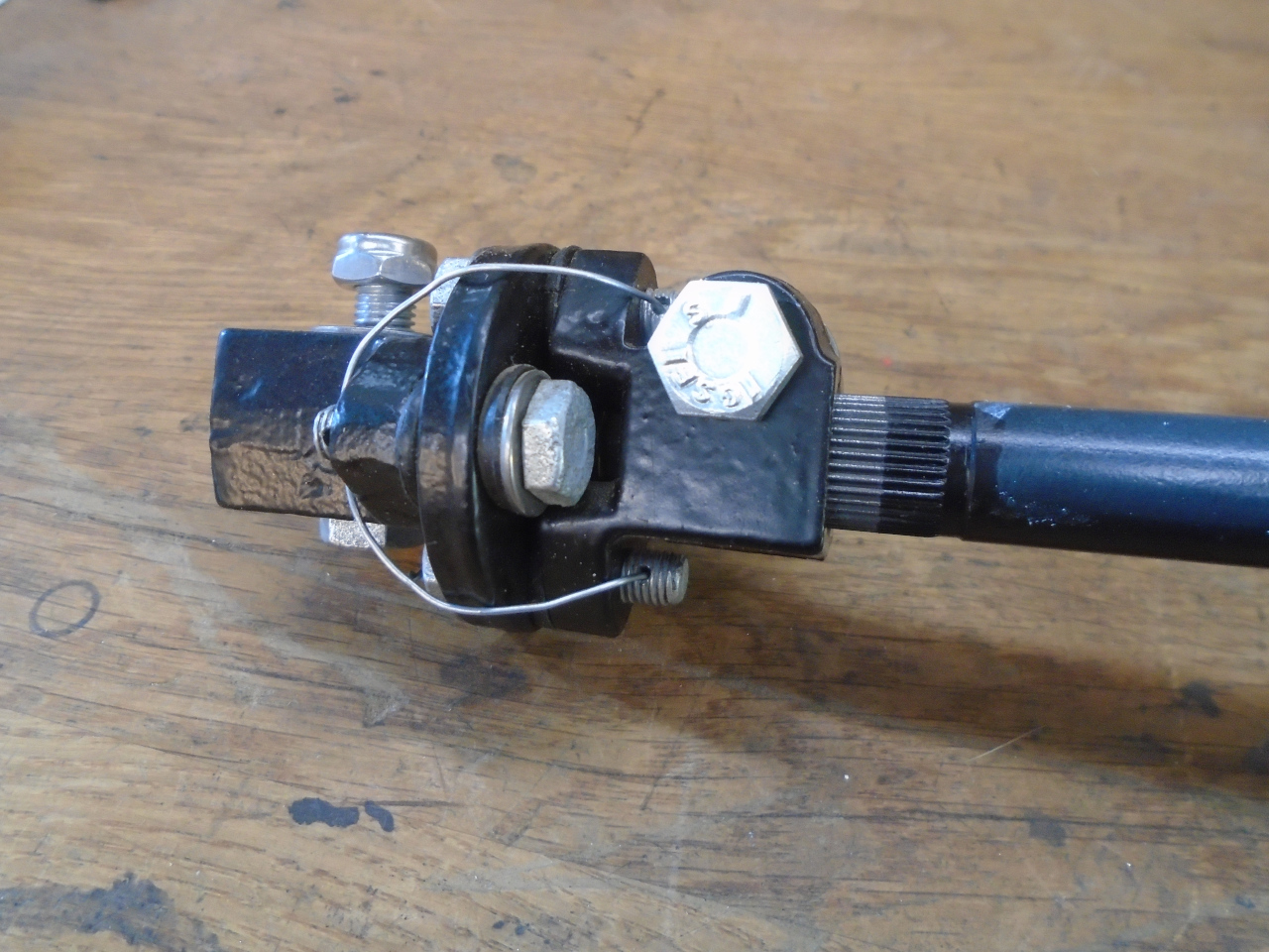
The last piece was the little U joint that goes between the column
and the rack and pinion. I took it apart, cleaned up the rust, and
powder coated or replated the metal parts. The rubber parts
seemed good enough to re-use.
This dude goes on the shelf.
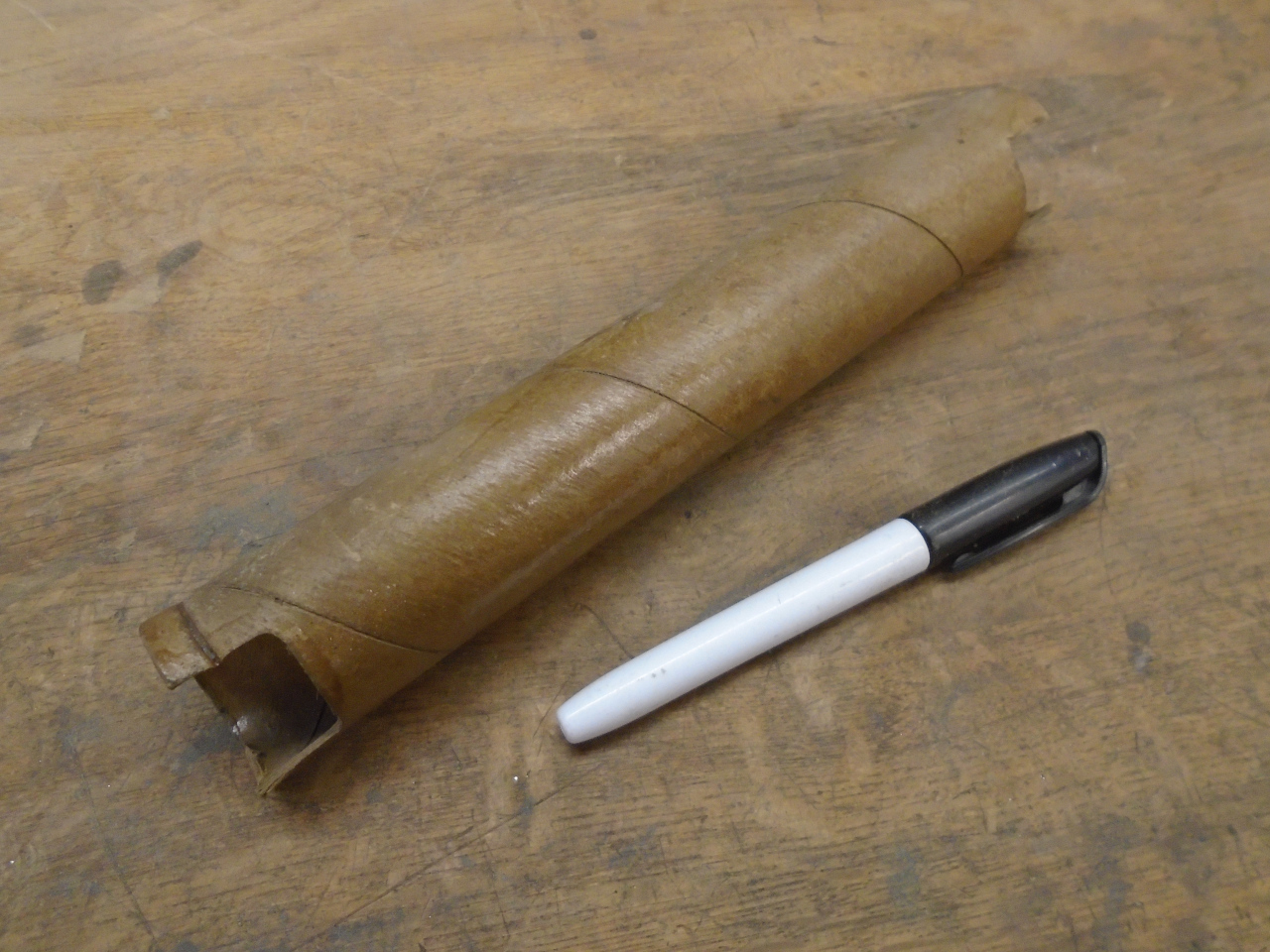
As sometimes happens in these kinds of projects, I had a part left
over. It's a cardboard tube that was found on the lower part
of the column housing. You can see it in the first few pics
above. I can see no earthly purpose for this tube.
After a search, consensus seems to be that it may have been some
kind of install gauge that was just left in place. I'll keep
it for a while in case I'm wrong.
This was an enjoyable project, and was good for a couple of
pleasant days in the nice warm shop. Cost was
minimal--probably under $20, including consumables.
Comments to Ed at elhollin1@yahoo.com
To my other GT6
pages