To my other GT6
pages.
April 18, 2020
Horns
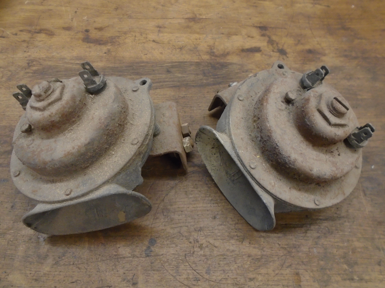
My car, and most Triumphs of this era
came with a pair of Lucas 9H Windtone horns. These were
pretty widely used at the time, even seeing some duty on
motorcycles. The horns look similar, but are different in
that one honks a higher note than the other.
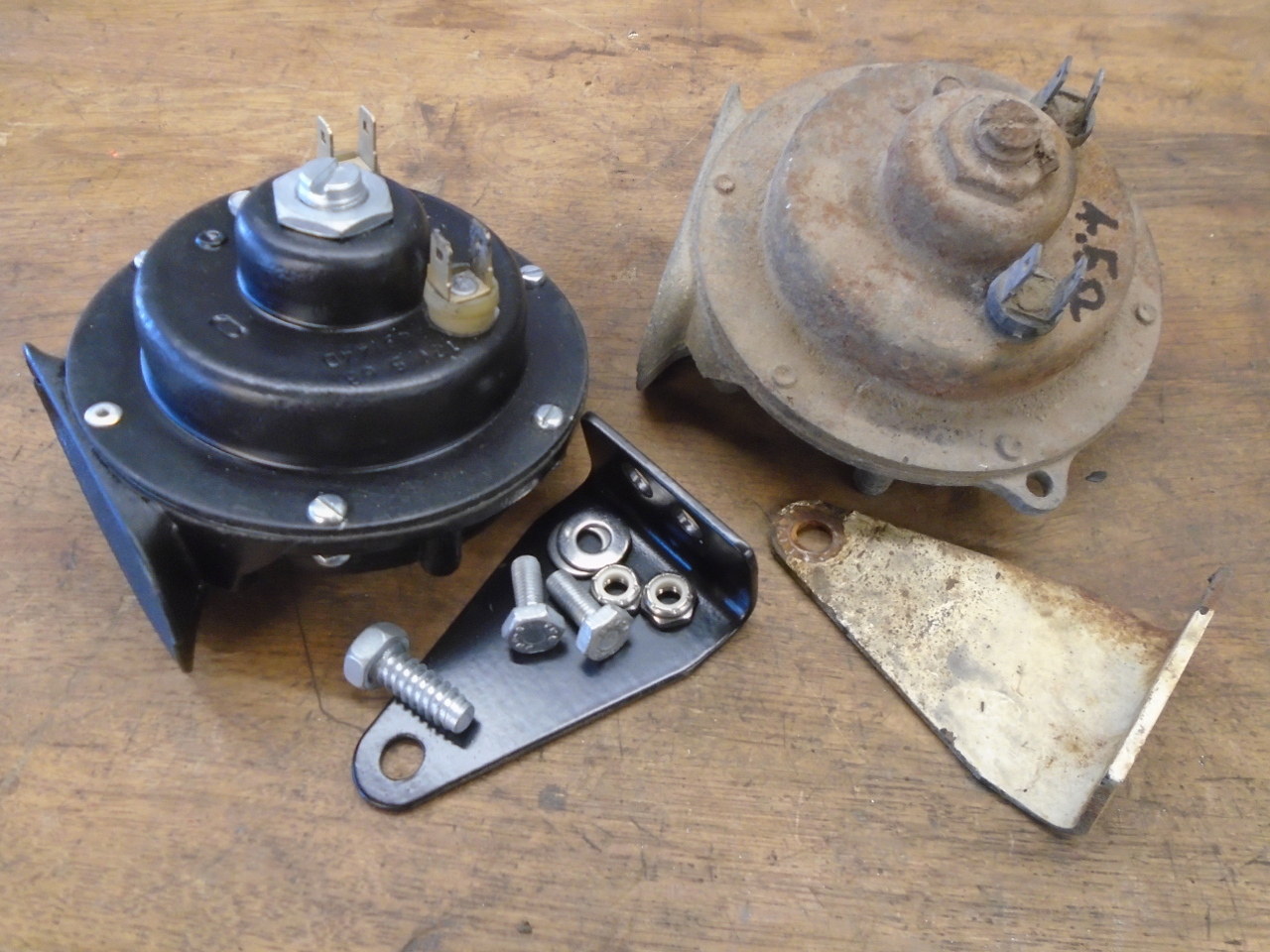
Considering where the horns live, right inside the front grille,
they didn't look too bad--just dirty and rusty. You can
just make out the "H" and "L" markings on the mouths of the
horns, indicating the high and low note units, respectively.
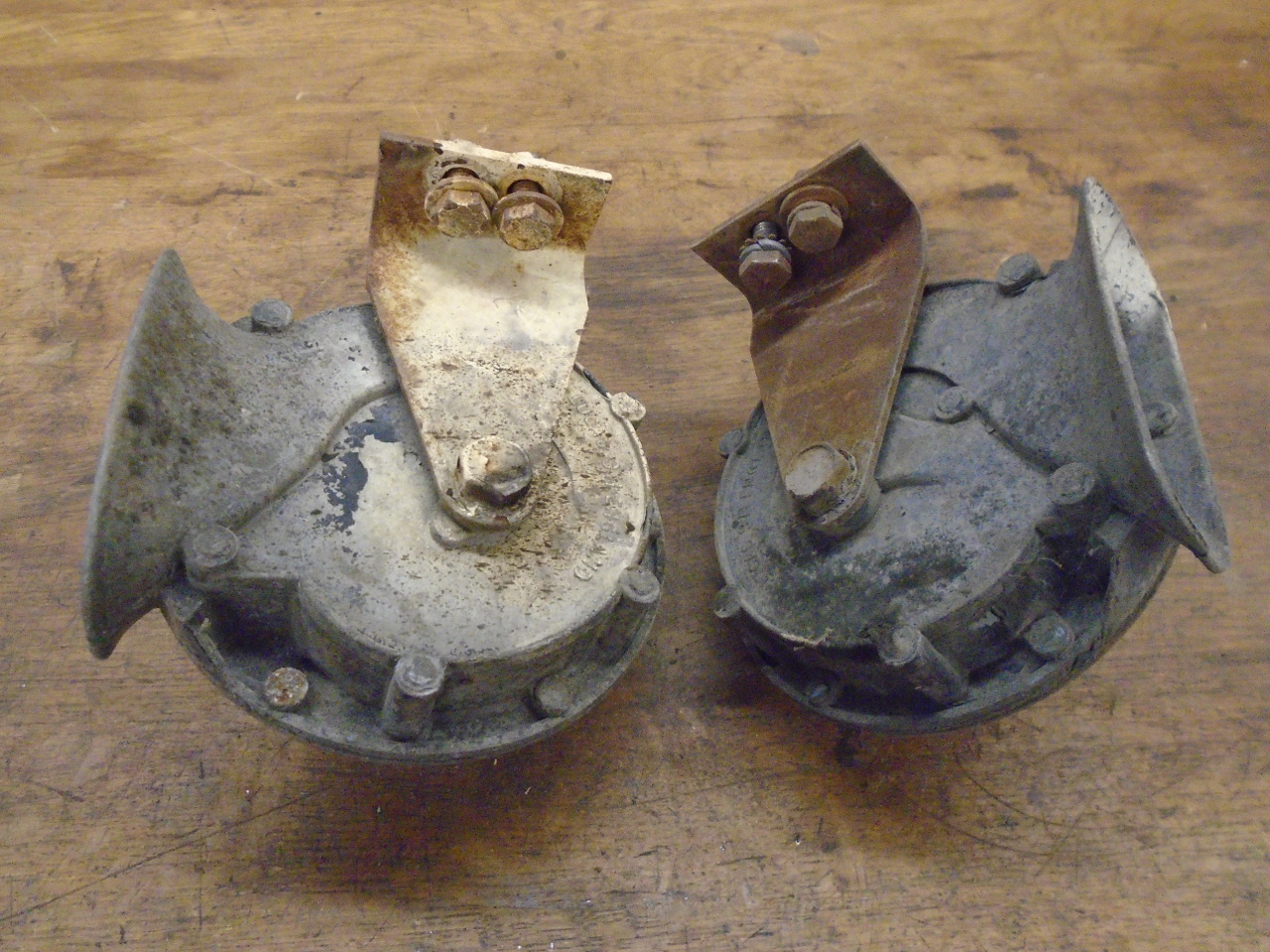
I tested the horns to a 12 volt power supply, and they both were
trying, but the tones were weak and erratic. I measured
the resistance across the terminals. It should be
something less than one ohm. The fact that the resistances
weren't infinite was a good sign, but he high readings probably
indicated dirty contacts inside.
I do know that generic horns for cars are a commodity item--they
can be bought cheaply at any auto store. There are even
reproduction Windtone horns available for not much money.
Either of these options would be thoroughly sensible.
But that's not the way I roll.
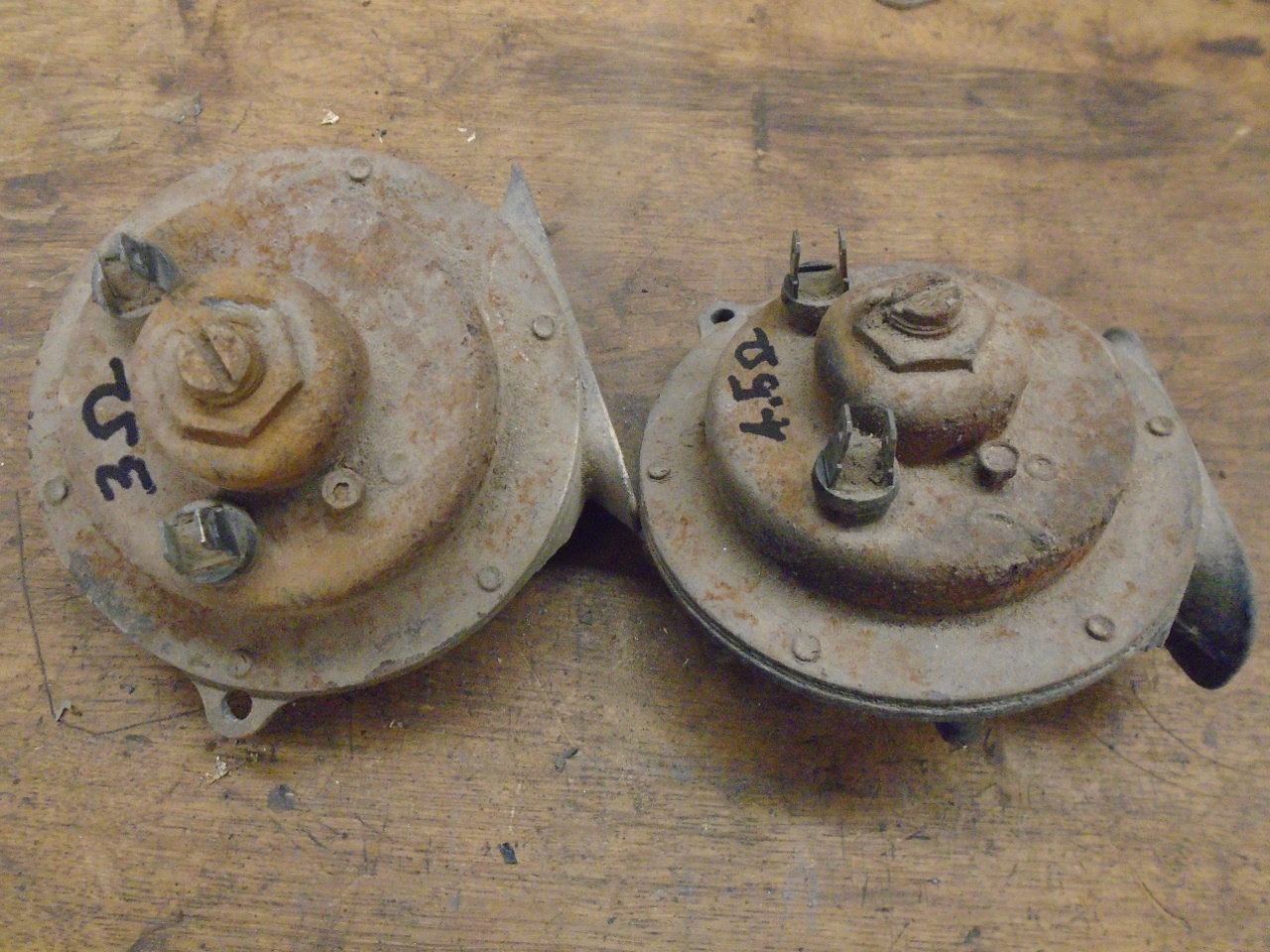
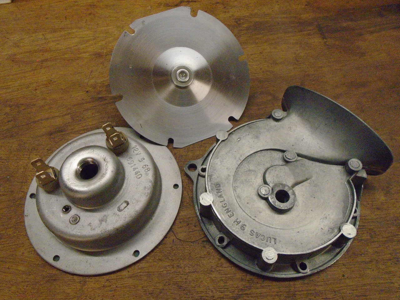
So I had to break into the horns. They are each held
together with six rivets. Drilling those out revealed that
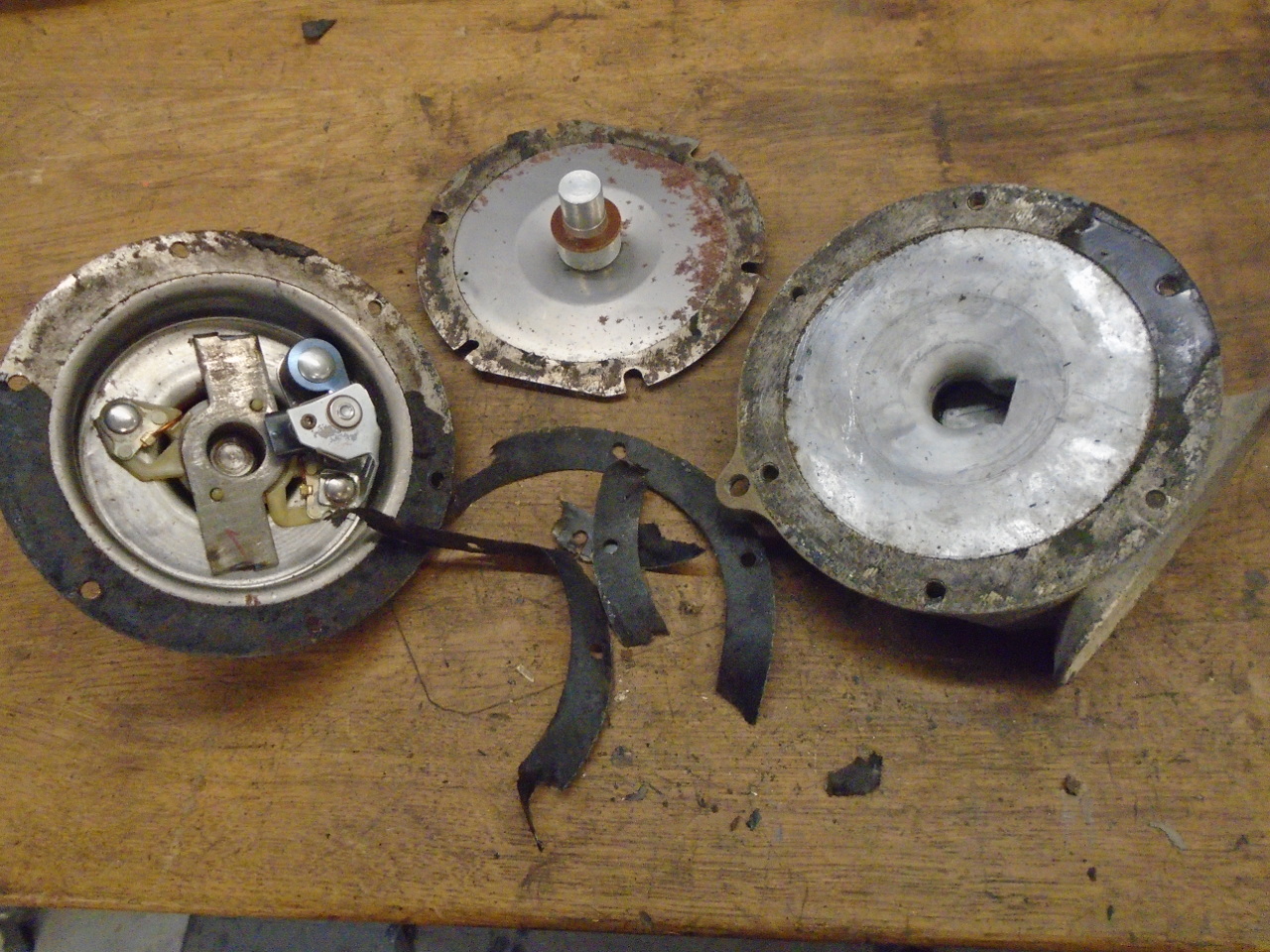
the horn was composed of two body halves with a thin metal
diaphragm sandwiched between. One body half was a pot
metal casting of a rolled up horn shape.The other half contained
the electrics: a coil of wire forming an electromagnet, and a
set of contacts in series with the coil. With the contacts
normally closed, 12 volts applied to the external connections
will energize the magnet. It pulls in a steel slug
attached to the center of the diaphragm. After traveling
some small distance, a collar on the slug contacts a finger on
the contacts, opening them. This stops the current, and
the slug retreats to start the cycle again. This of course
happens hundreds of times per second. The vibrating
diaphragm gets air moving, and the horn shape of the channel
leading to the outside reinforces the sound.
Everything cleaned up pretty well with a light blasting. I
powder coated the horn casting, but was a little apprehensive
about subjecting the electrics to the oven heat, so that half
was just primed and painted. Not much hope of finding
those gaskets, so they are home made.
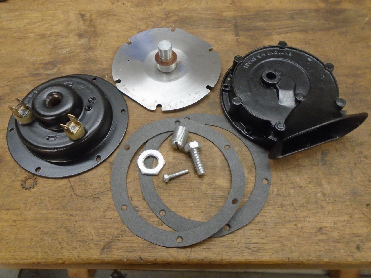
Cleaned the contacts by pulling a strip of very fine abrasive
paper through them, and put everything back together. I
did one unit at a time in case I had to refer to the virgin
unit.
The second one went a lot faster. There are two
adjustments on each of these horns. First, there is a big
threaded stud and lock nut. The stud is a stop for
the diaphragm stud, limiting how far it can travel.
Second, there is a small screw that bears on the fixed side of
the contacts, allowing it to be moved slightly. Oddly,
that screw is left hand threaded.
I measured the protrusion of both of the adjustment screws
before I removed them, so I could at least have a good starting
point for tweaking them. Neither of the screws changed the
pitch of the horn--they are just mechanical adjustment of the
circuit-breaking action of the contacts. If they are too
far from optimum, the horn just clicks or grunts.
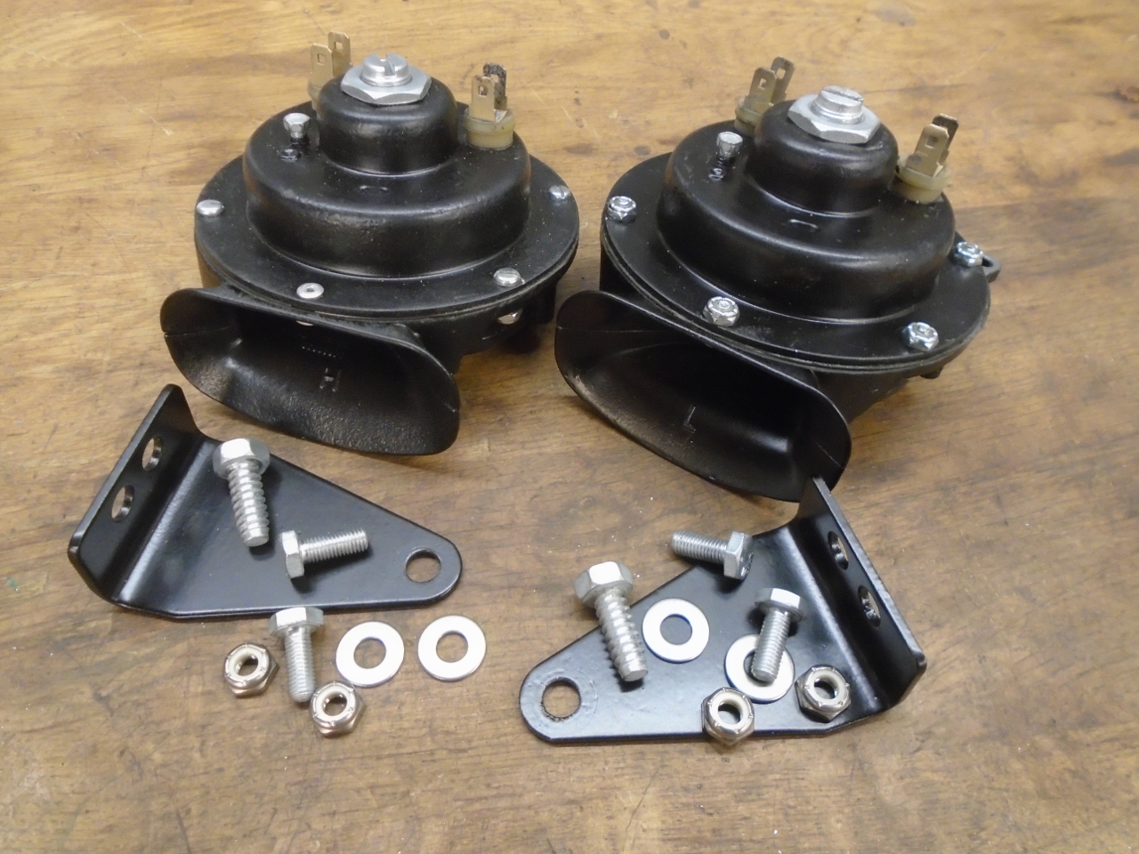
One horn worked fine after assembly without much tweaking.
The other wouldn't do anything. After fiddling a lot with
the adjustments, I finally measured the resistance. It was
around 12 ohms, suggesting some crud still in the
contacts. So, apart it came for another contact cleaning,
and that did the trick.
Factory frequency spec for the horns is 390-400Hz for the low
tone horn, and 490-500 Hz for the high one. My horns were
in or very near spec, together approximating most of a
harmonious G major chord.
I like quick and fairly easy projects like this. Low
stress, good chance of success, and little or no
investment. And it was good for a few pleasant afternoons
in the shop. Cost was essentially zero.
Comments to Ed at elhollin1@yahoo.com
To my other GT6
pages.