January 10, 2019
Foundry Furnace
[All pics are clickable]
For
years, I've wanted to add some kind of foundry capability to my shop.
Besides being really interesting to me, there have been occasions
where a cast raw piece would have made a fabrication so much easier.
I've made a couple of spin-on oil filter adaptors for old
vehicles, and starting with an aluminum casting would have really
simplified those projects.
So,
a few months ago, I decided now was the time. First, I needed a
furnace. I did quite a bit of research on DIY melting furnaces
and came up with a design that I think should meet my needs at least
for the near term.
The basic furnace is made out of a castable refractory material allegedly rated to 3000°F.
I
made molds to cast the refractory into. I know that many if not
most furnace builders try to use found objects for the molds--buckets,
tanks, or barrels and such. Making purpose built molds allowed me
to get the exact dimensions I wanted without a search for something
suitable.
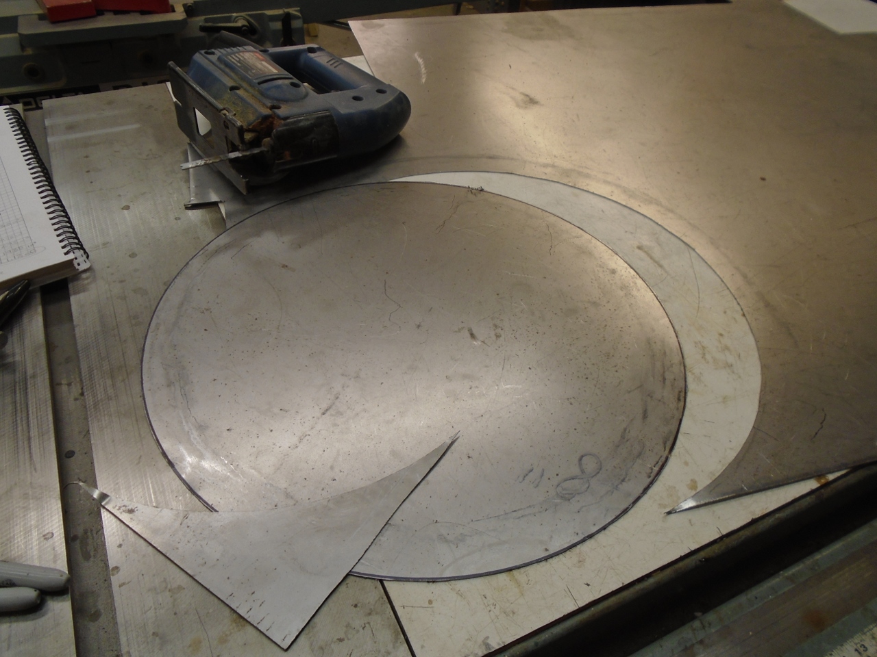
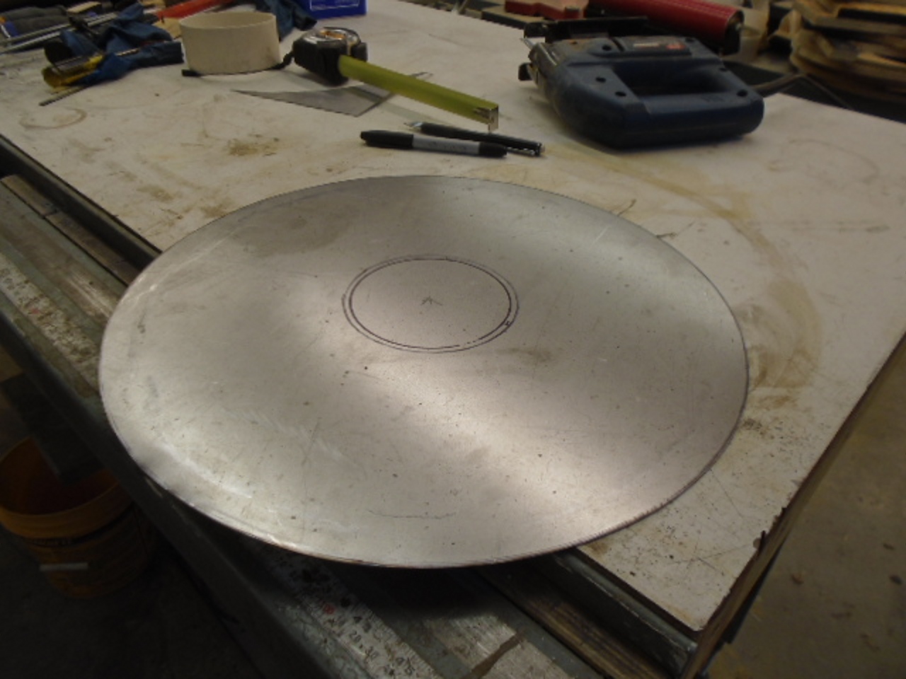
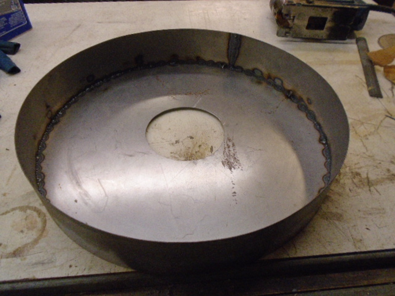
The
base was first. I started with a sheet metal disc that will be
the bottom surface of the furnace. The base mold was set on top
of that, and was lined with some temporary sheet metal.
.
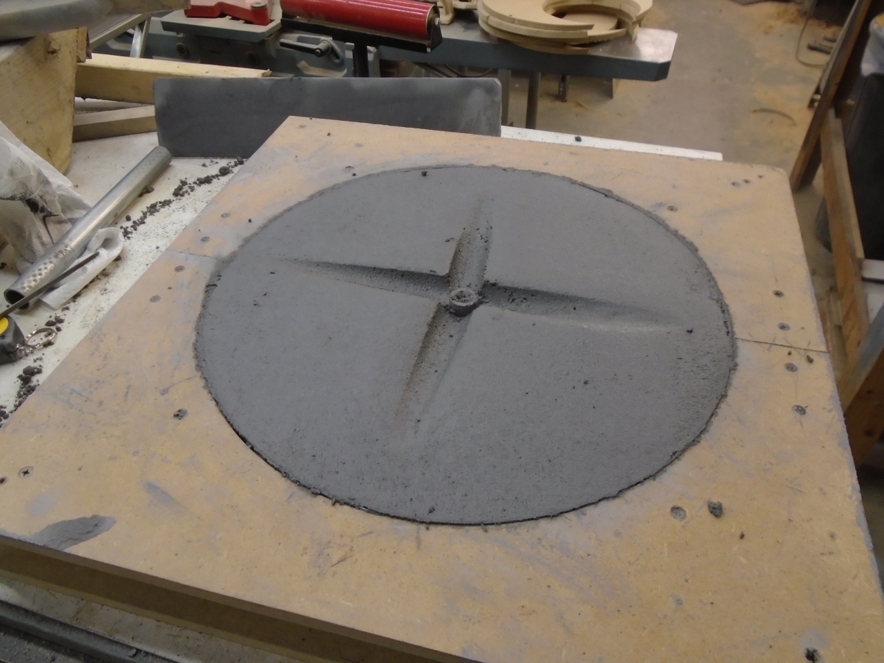
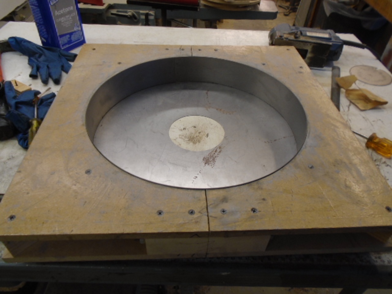
Then
poured the refractory. "Poured" is a bit of a misnomer, since
mixing according to the data sheet results in a very dry mix that
basically has to be pounded into place. Vibration seemed to help
a little, but the data sheet made no mention of it.
The sloped grooves are to direct molten metal to the bottom drain hole in the event of a broken crucible.
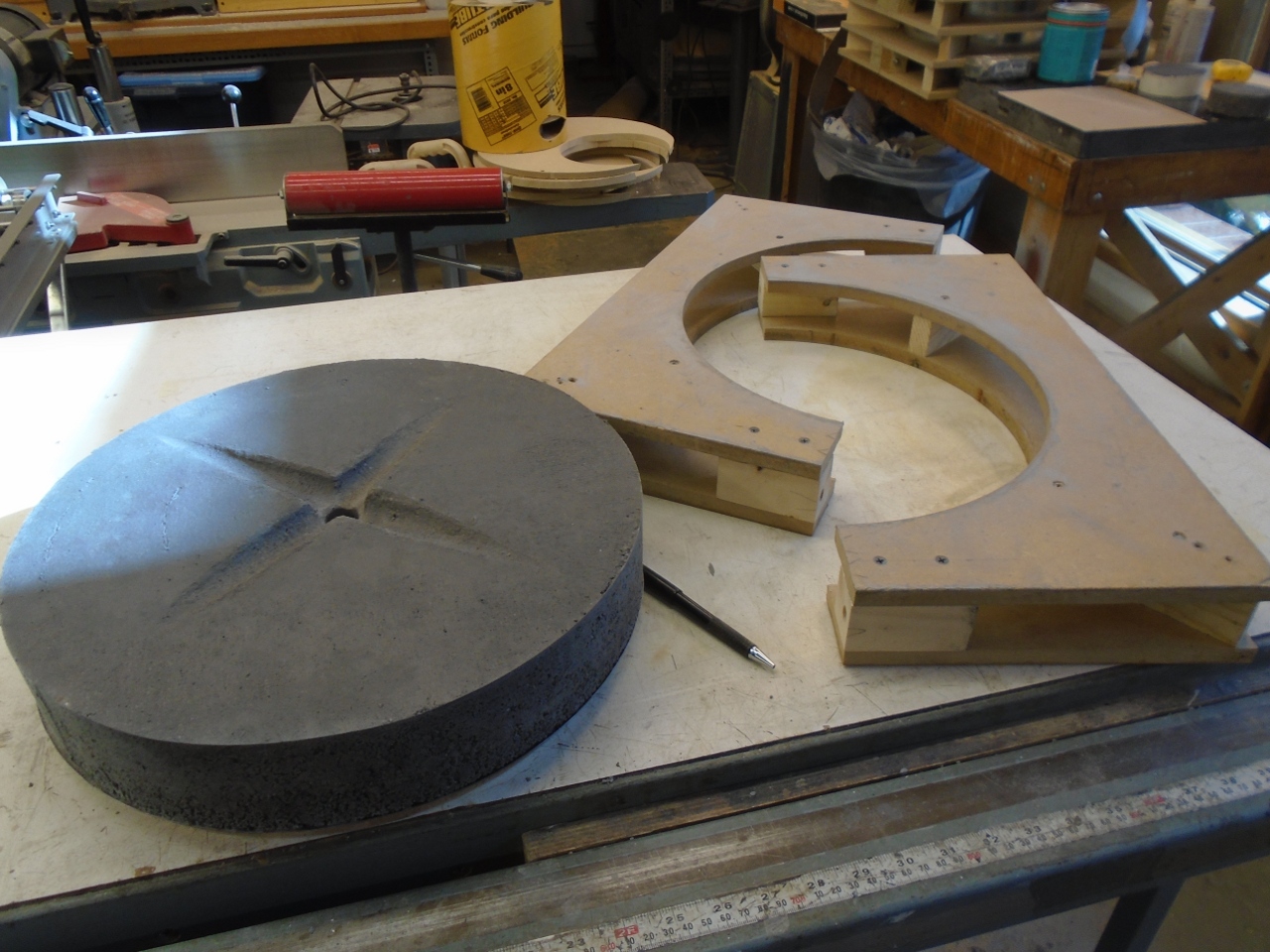
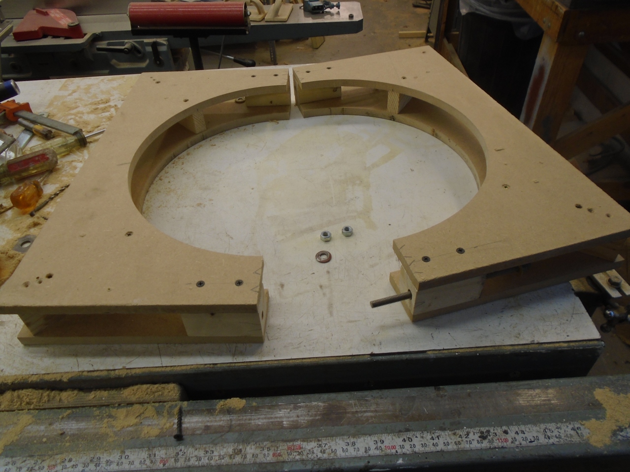
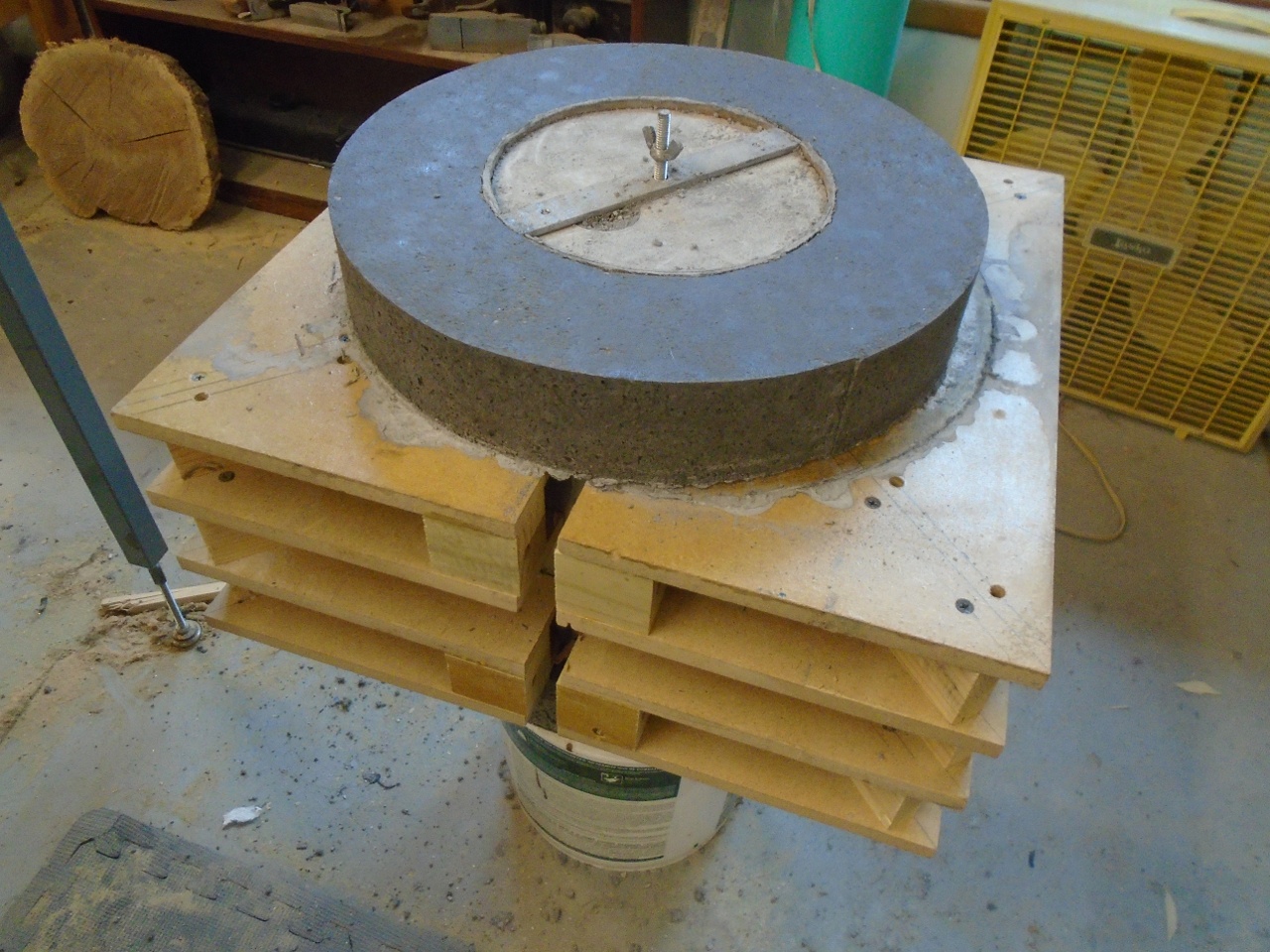
Then
the main body mold. It was in two pieces--one for the belly of
the furnace, and on top ot that, a larger diameter mold to form the top
flange of the furnace. The top mold ia actually the same one used
for the base.
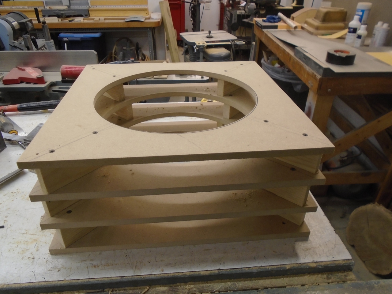
The
lower and upper molds were registered and fastened together, then each
was lined with temporary sheet metal around the perimeter. Then
an 8-inch carboard tube was inserted to form the furnace chamber.
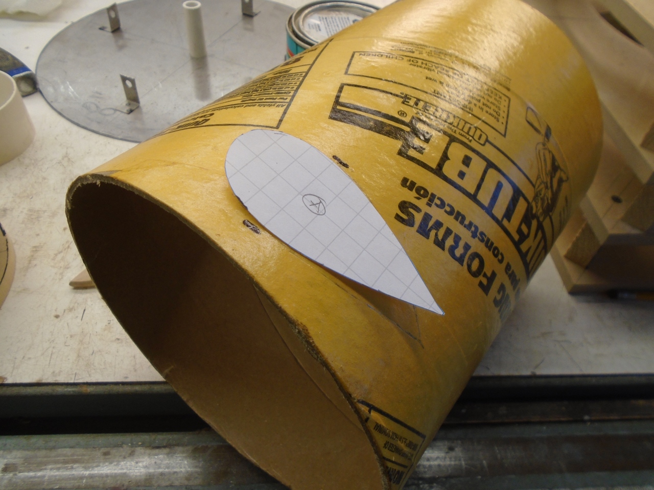
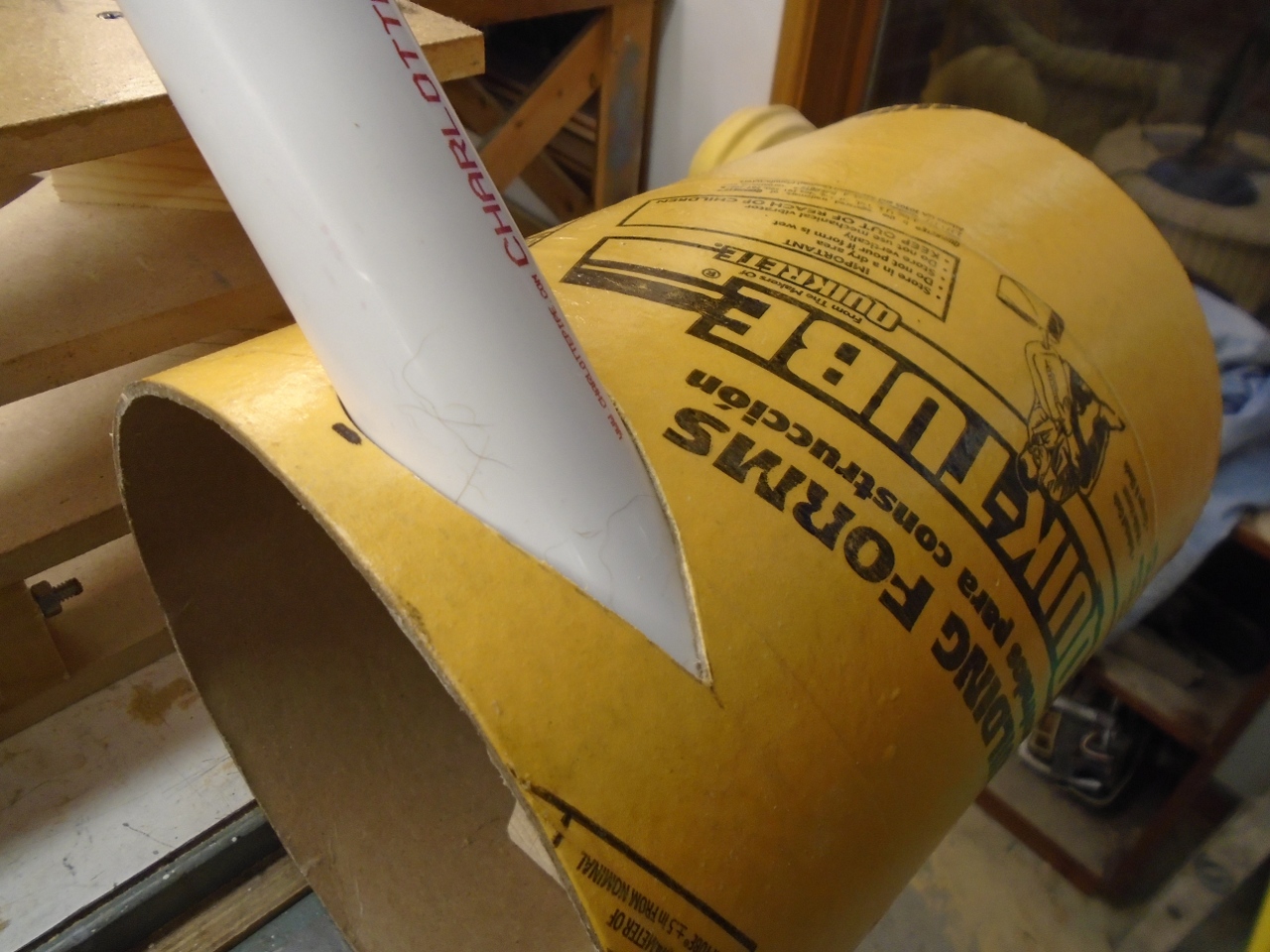
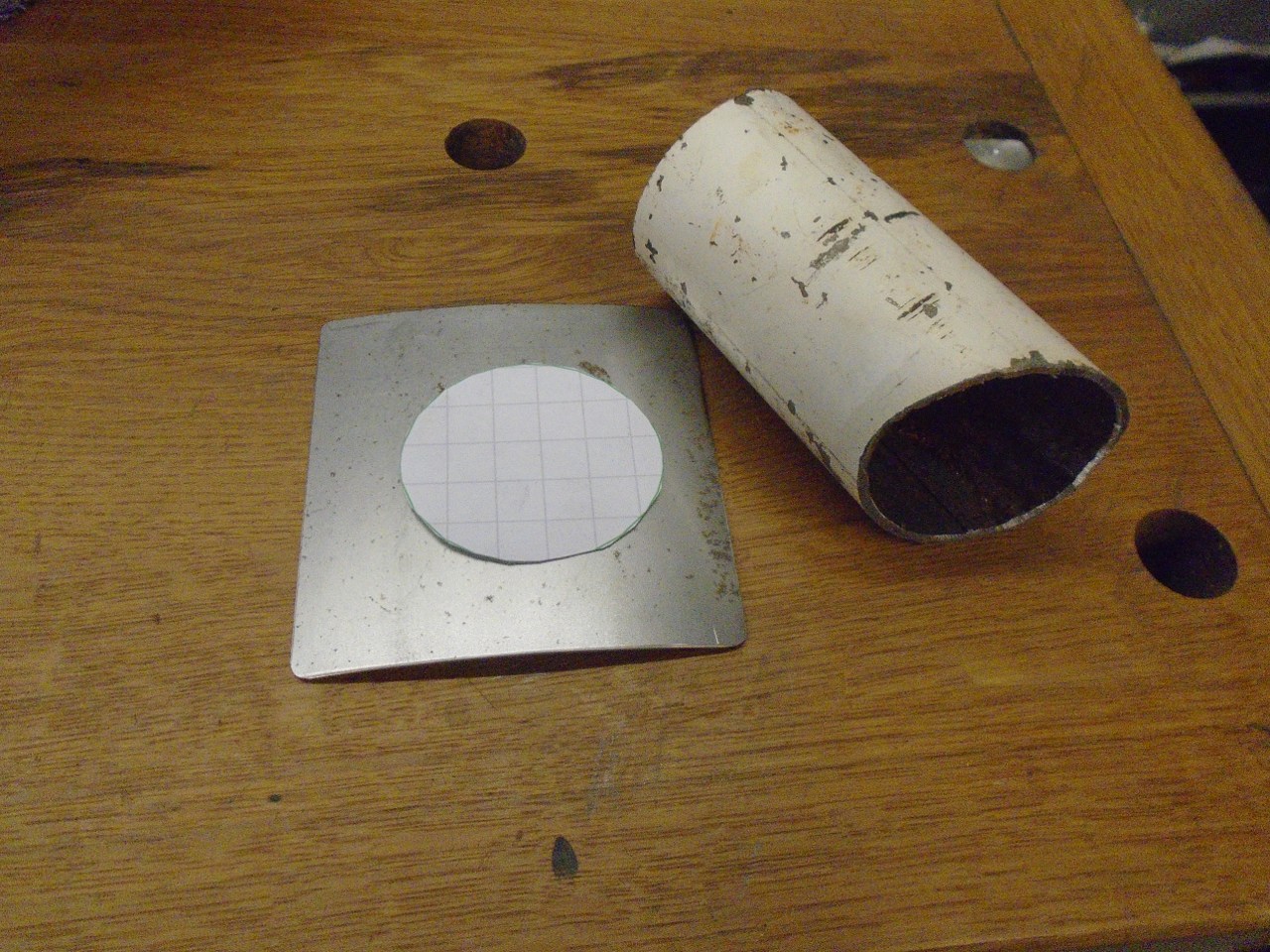
Before
the cardboard tube was put finally in place, I had to cut the hole for
the pipe that would form the burner opening. This is complicated
by the fact that the opening has to be essentially tanagent to the wall
of the chamber. Though there are ways to do this graphically, I
wimped out and used an on-line app that produced a full size pattern
for the hole.
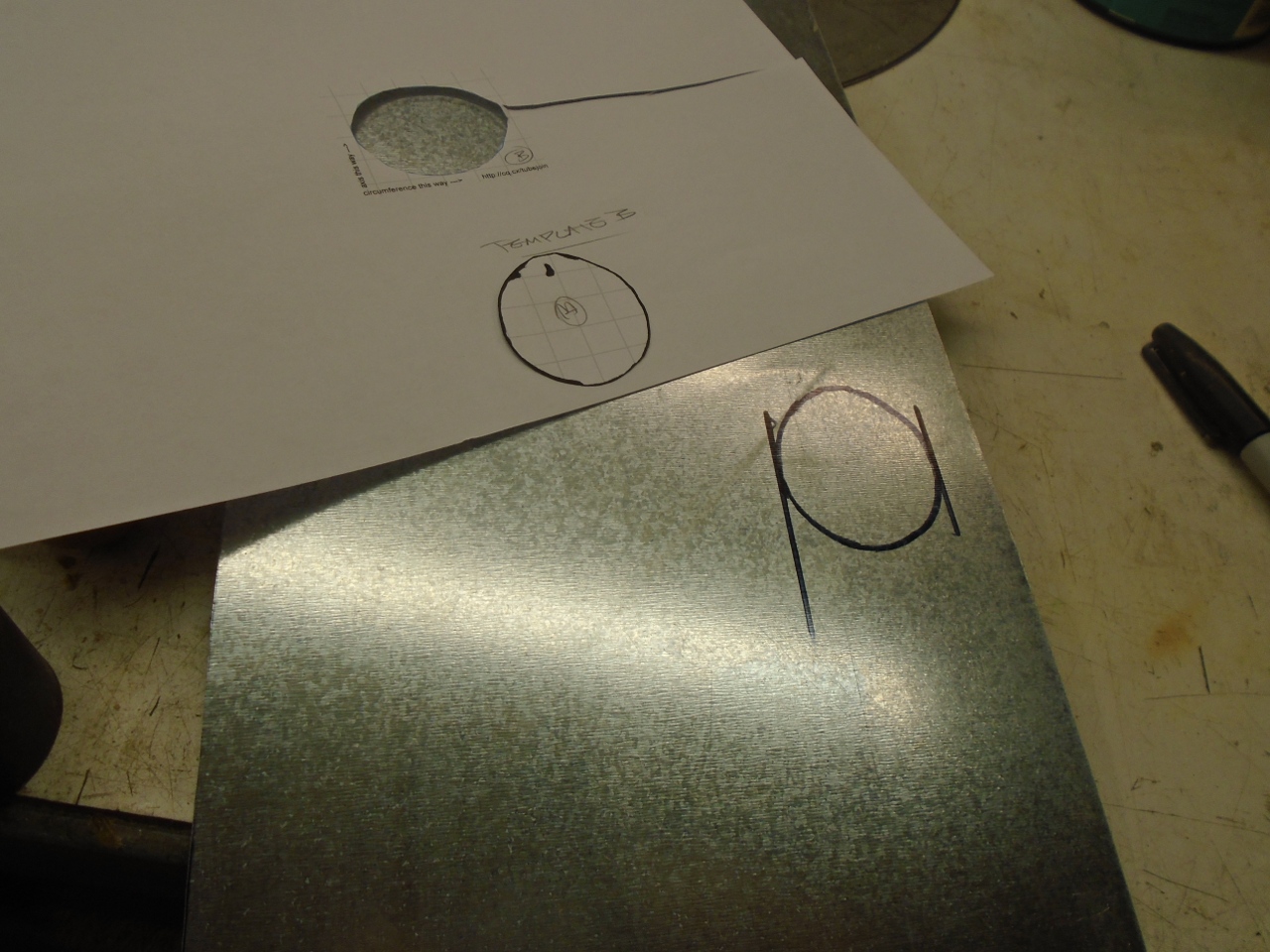
There also had to be a hole for the pipe in the sheet metal lining of the lower mold.
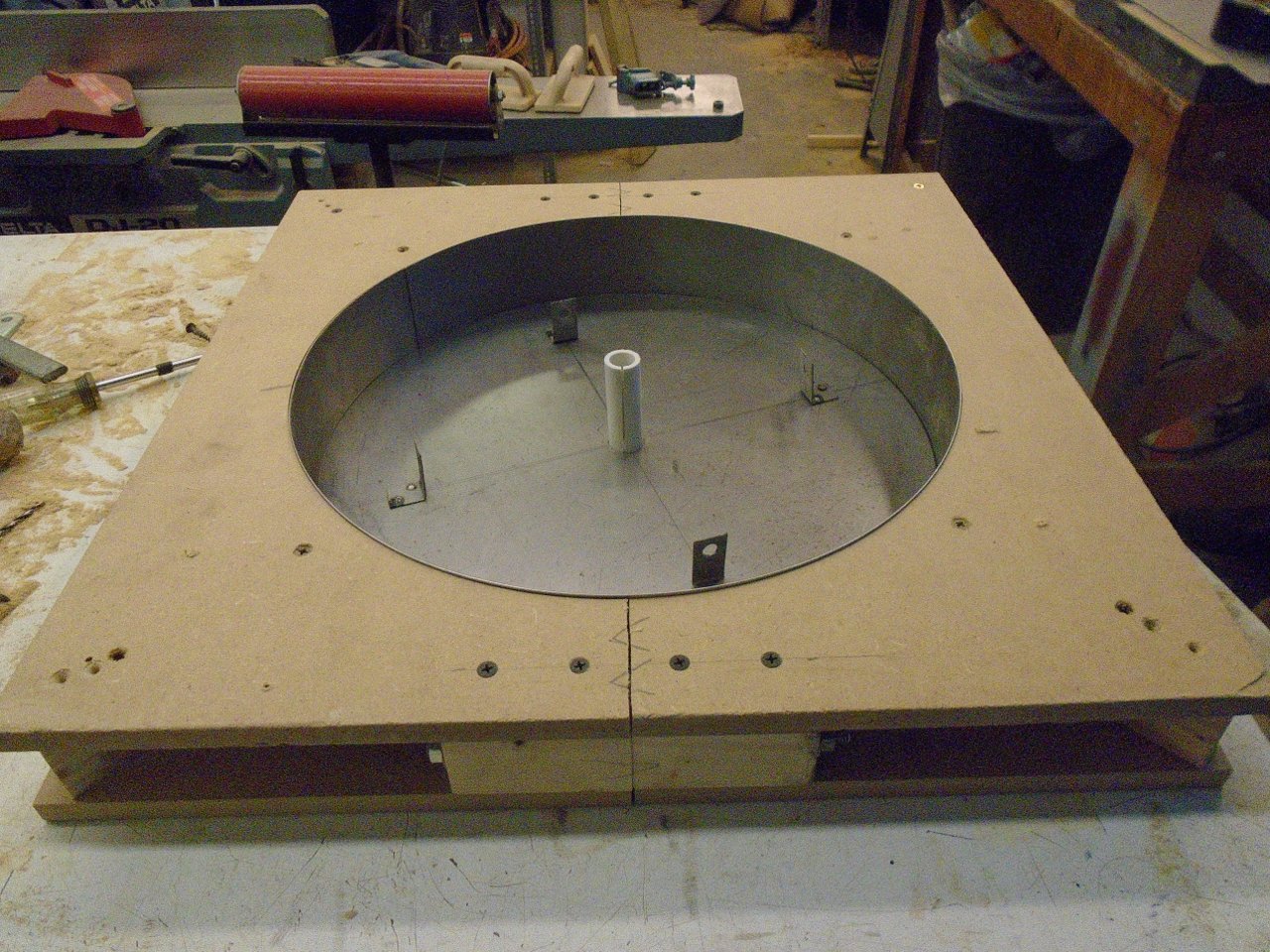
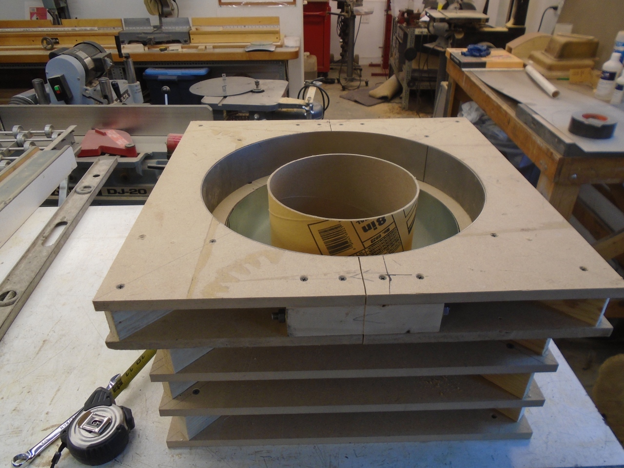
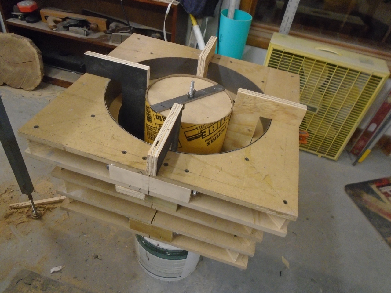
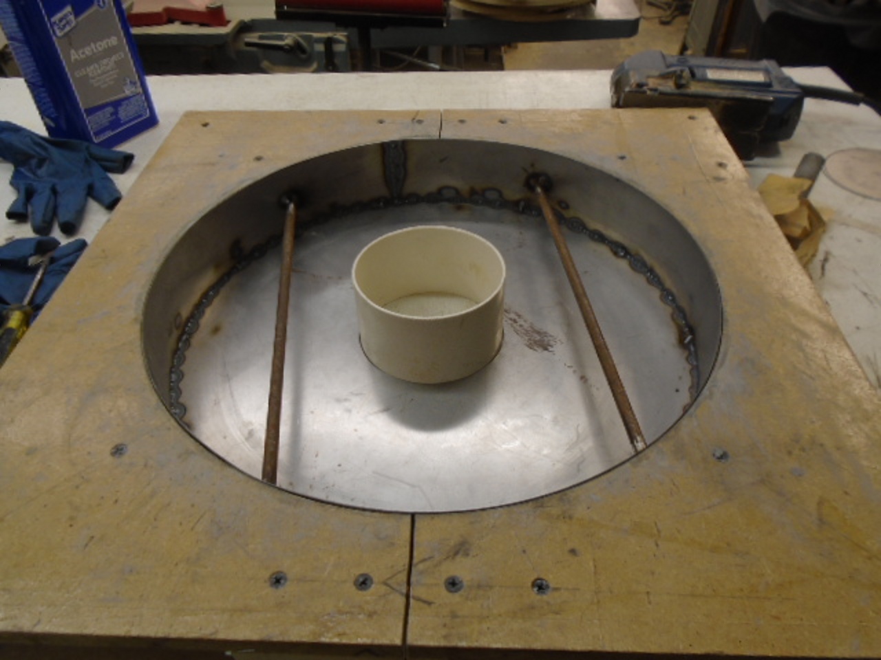
Then
assembled the mold on top of the already cast base to prepare for the
pour. Since the carboard form tube is designed to have concrete
on the inside, not the outside, I treated it with three of four coats
of varnish to hopefully keep it from getting too limp from moisture.
Also, having seen a video or two showing the form tube either
collapsing or trying to float out of the mold, I stacked a bunch of
plywood discs inside with spacers between to fortify the tube.
There is also a threaded rod going up the center of the tube so
that a metal bar can be tightened at the top to hold it down.
The "L" shaped wood pieces were to keep the tube centered in the mold. They moved up with the level of refractory.
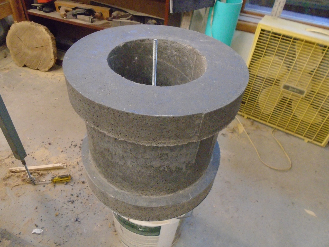
Then, in went about 75 pounds of refractory mix.
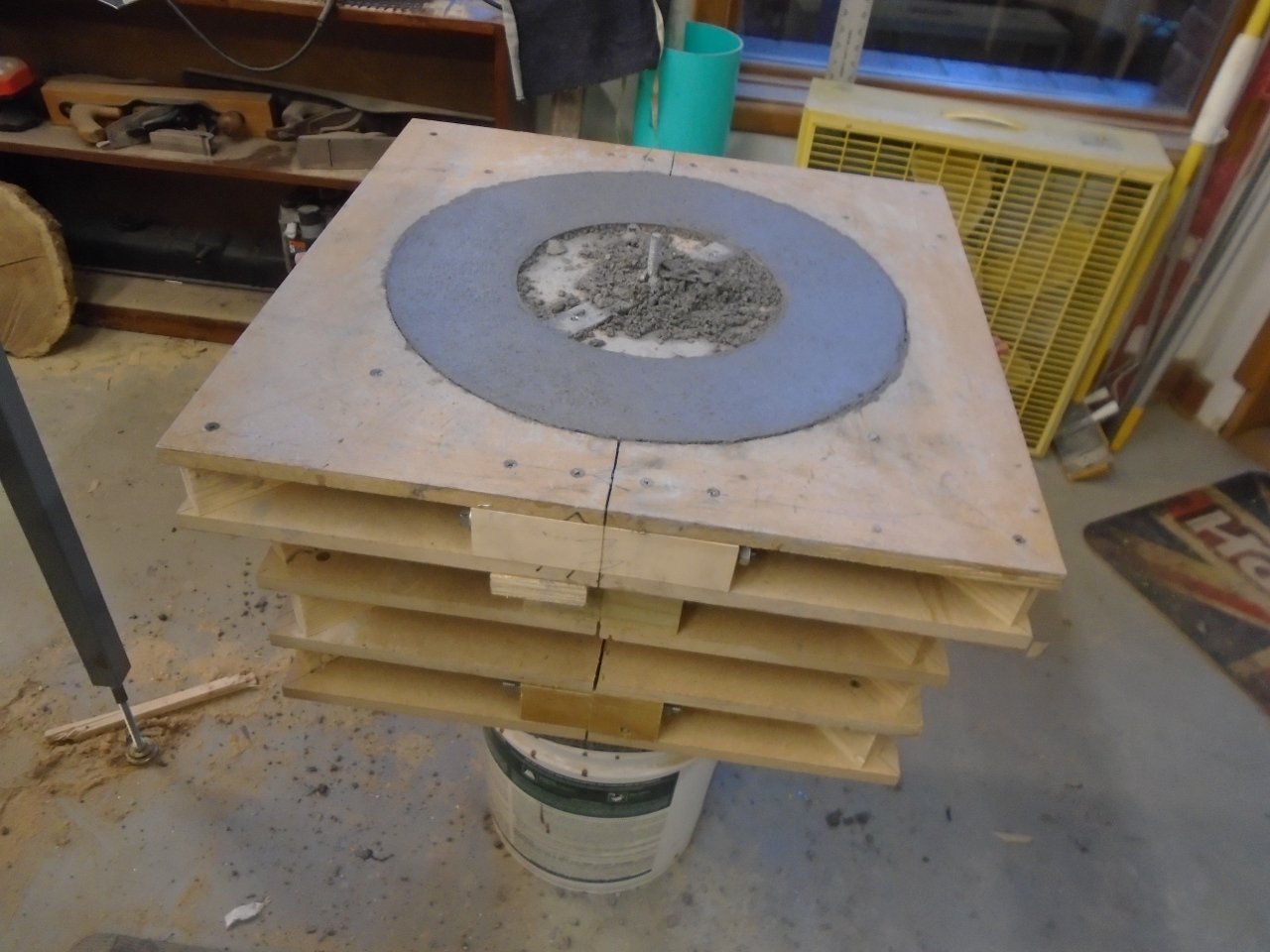
The next day, removed the molds.
To
make the top or lid, I re-used the same mold used for the base and the
flange of the body. This time, the sheet metal lining the
perimiter of the mold was not temporary. It would become part of
the furnace lid, so it got welded to the disc that would be the top
surface of the lid.
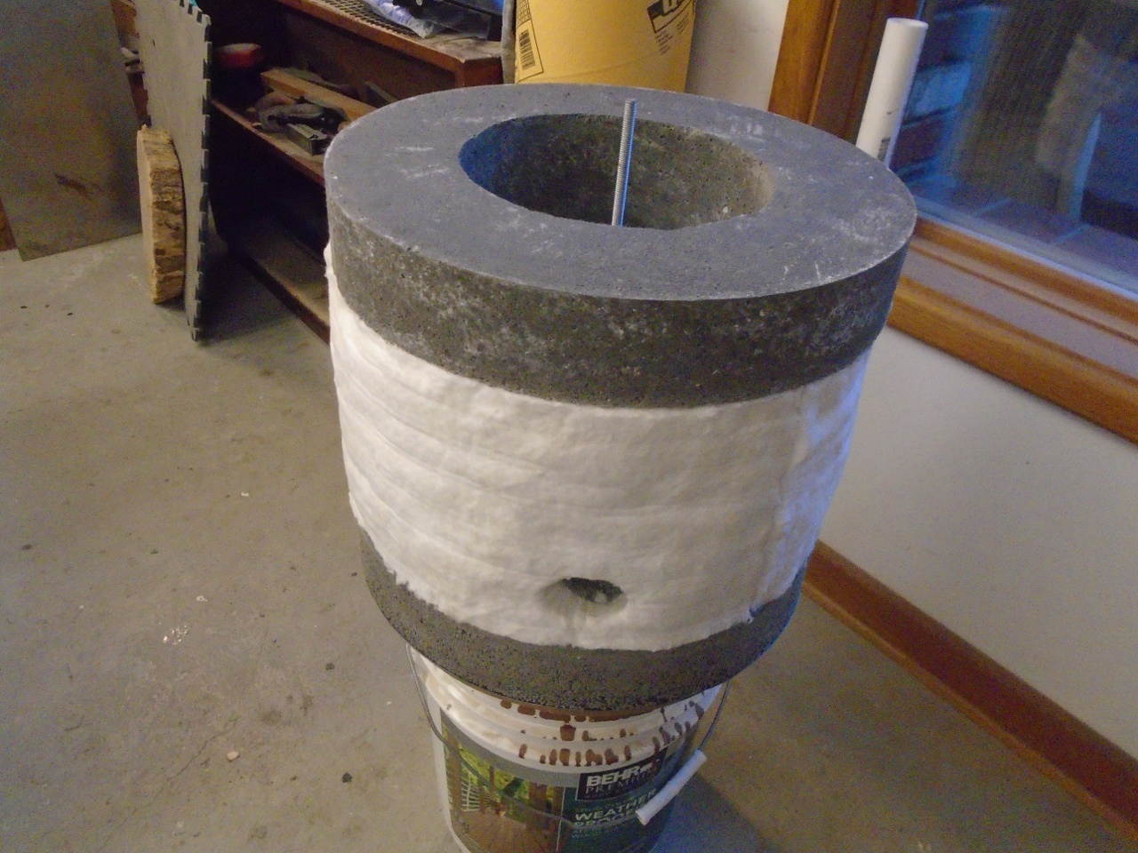
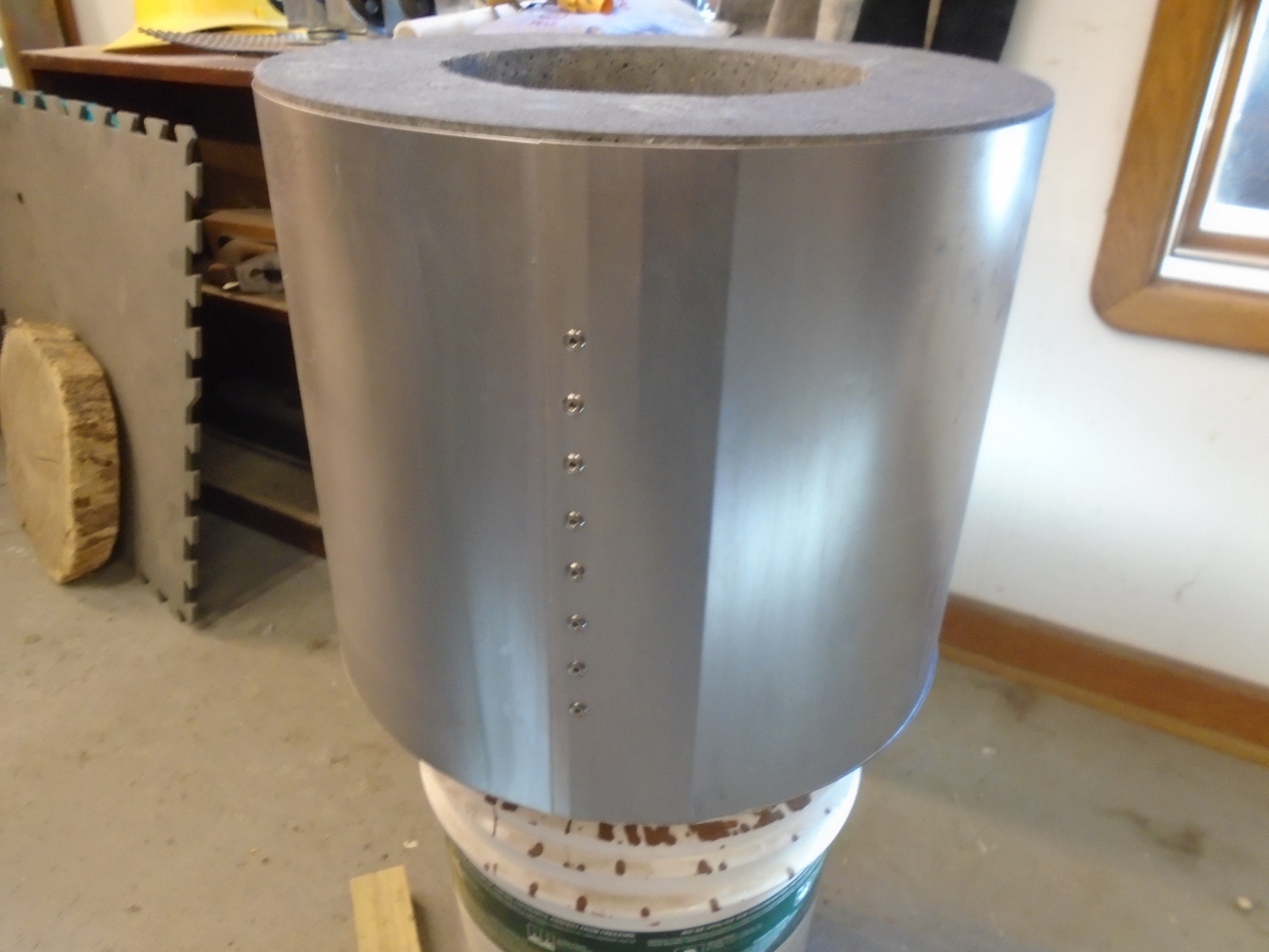
While
the poured top was setting, I turned back to the main furnace
body. A layer of one inch ceramic insulation blanket was applied
to the recess in the outer surface, and a hole cut for the burner to
pass through. The insulation should cut heat loss somewhat, and
maybe keep the outer surface of the furnace a little cooler.
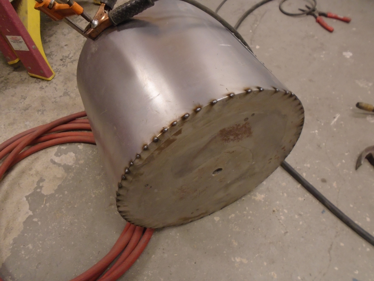
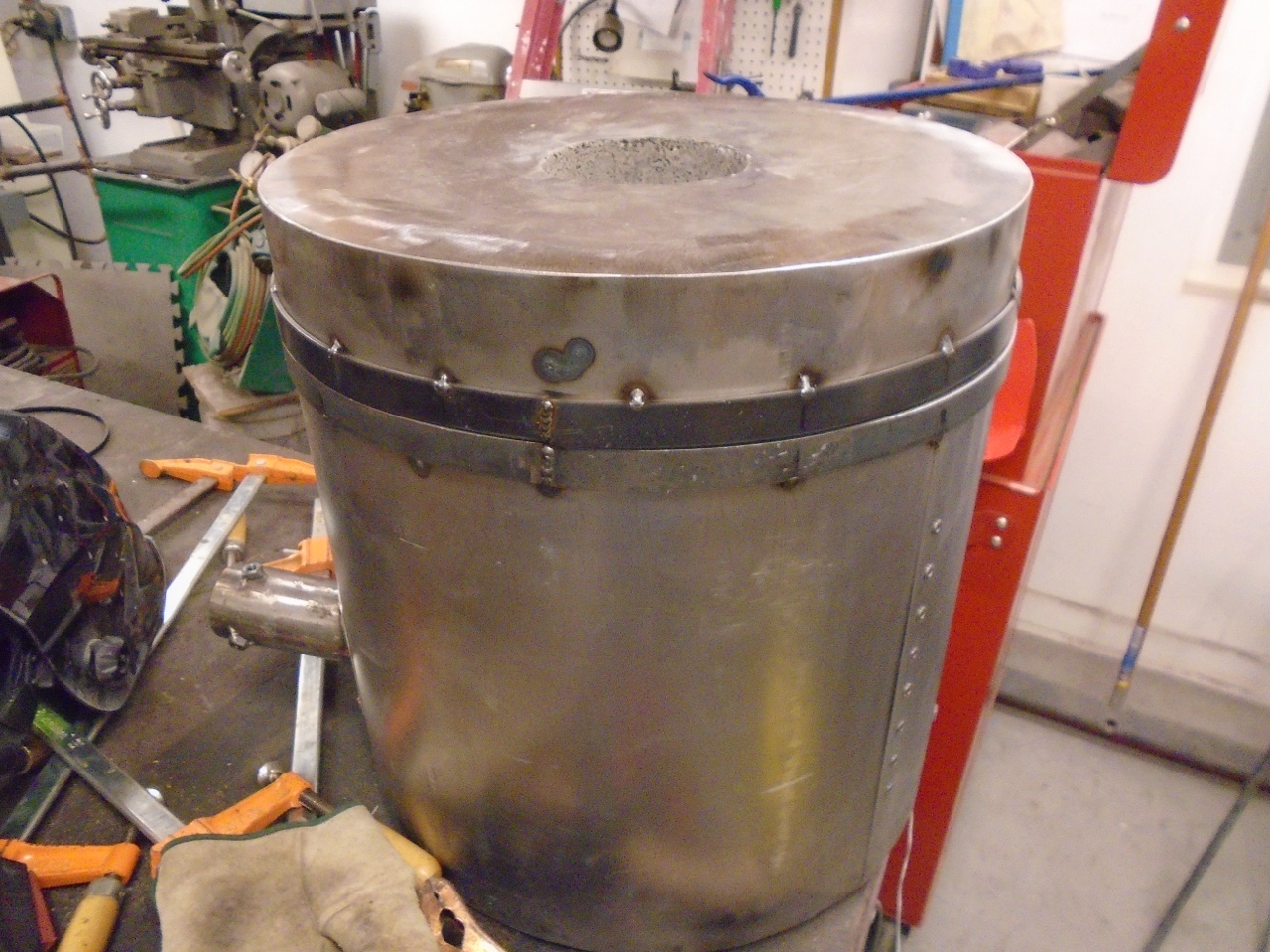
Then, a sheet metal skin was wrapped around the whole thing. It was overlapped and riveted...
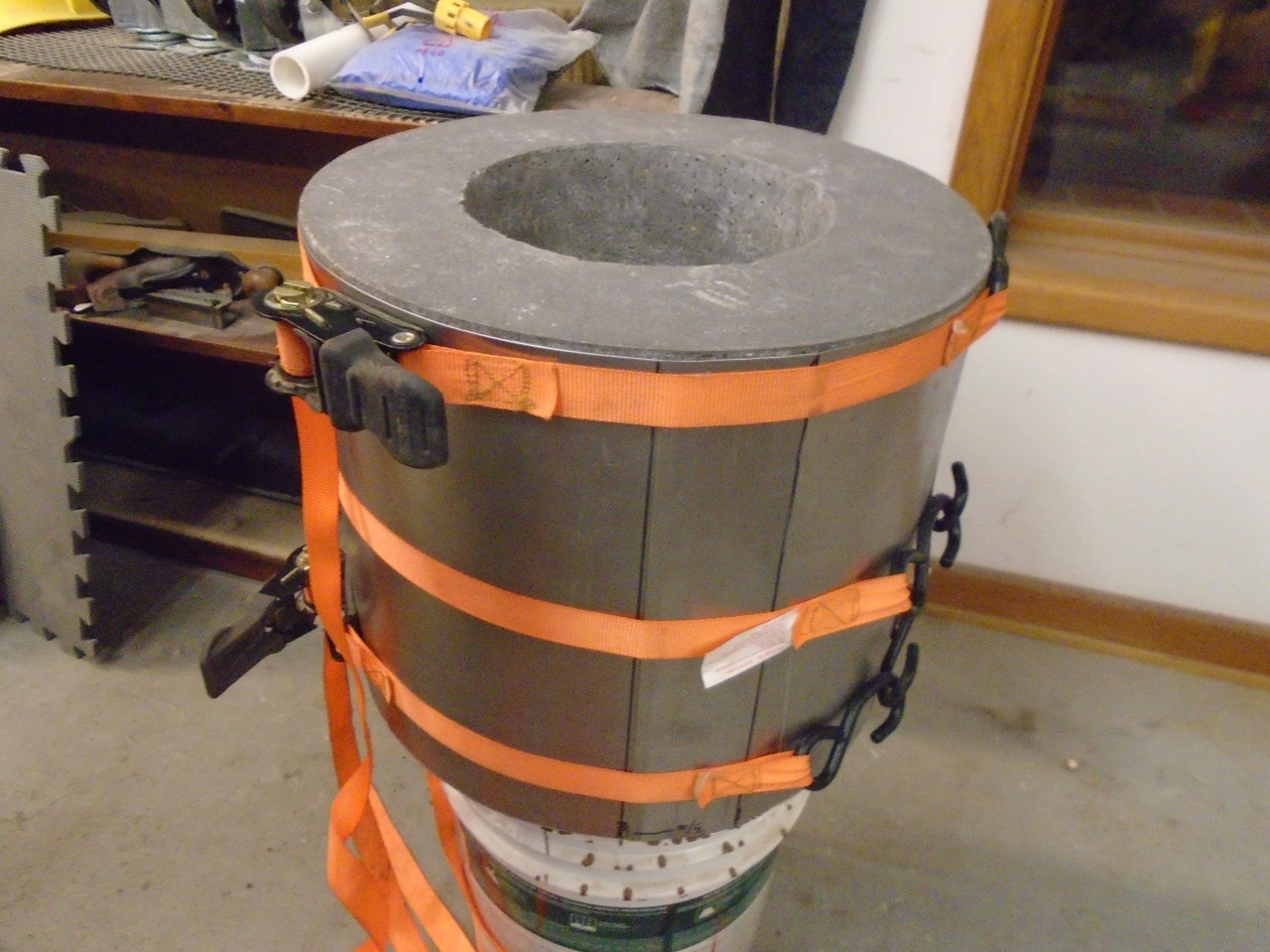
...then welded to the bottom disc.
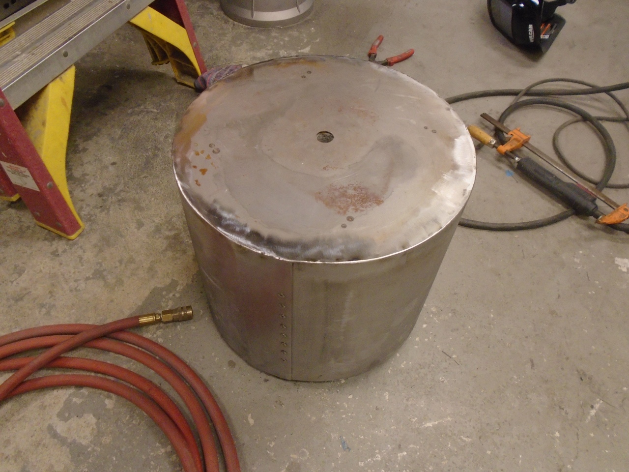
This is a fitting through which the gas burner will be inserted and retained in the furnace.
Then added these rings to sort of bulk up the sheet metal edges of the furnace and lid.
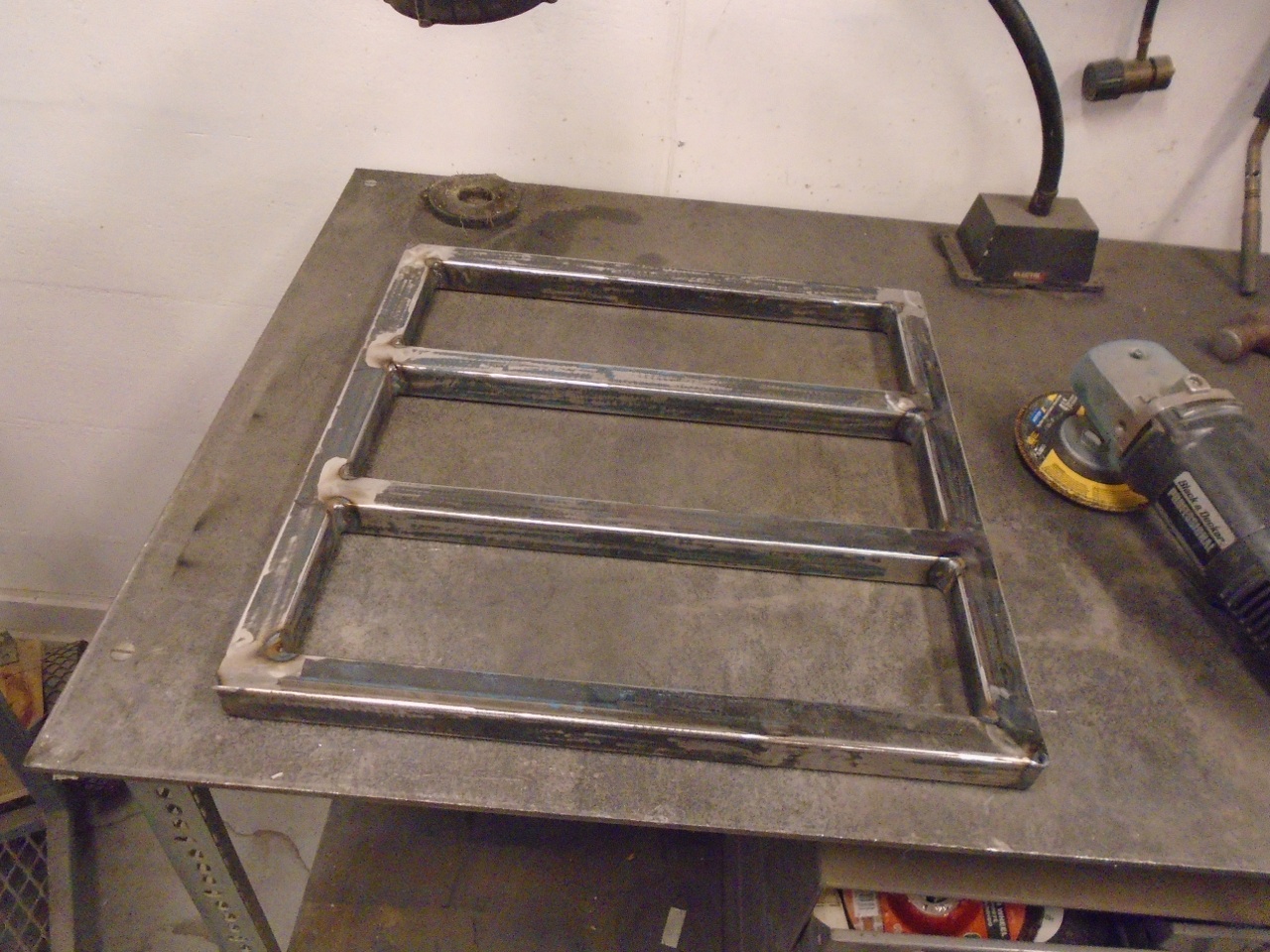
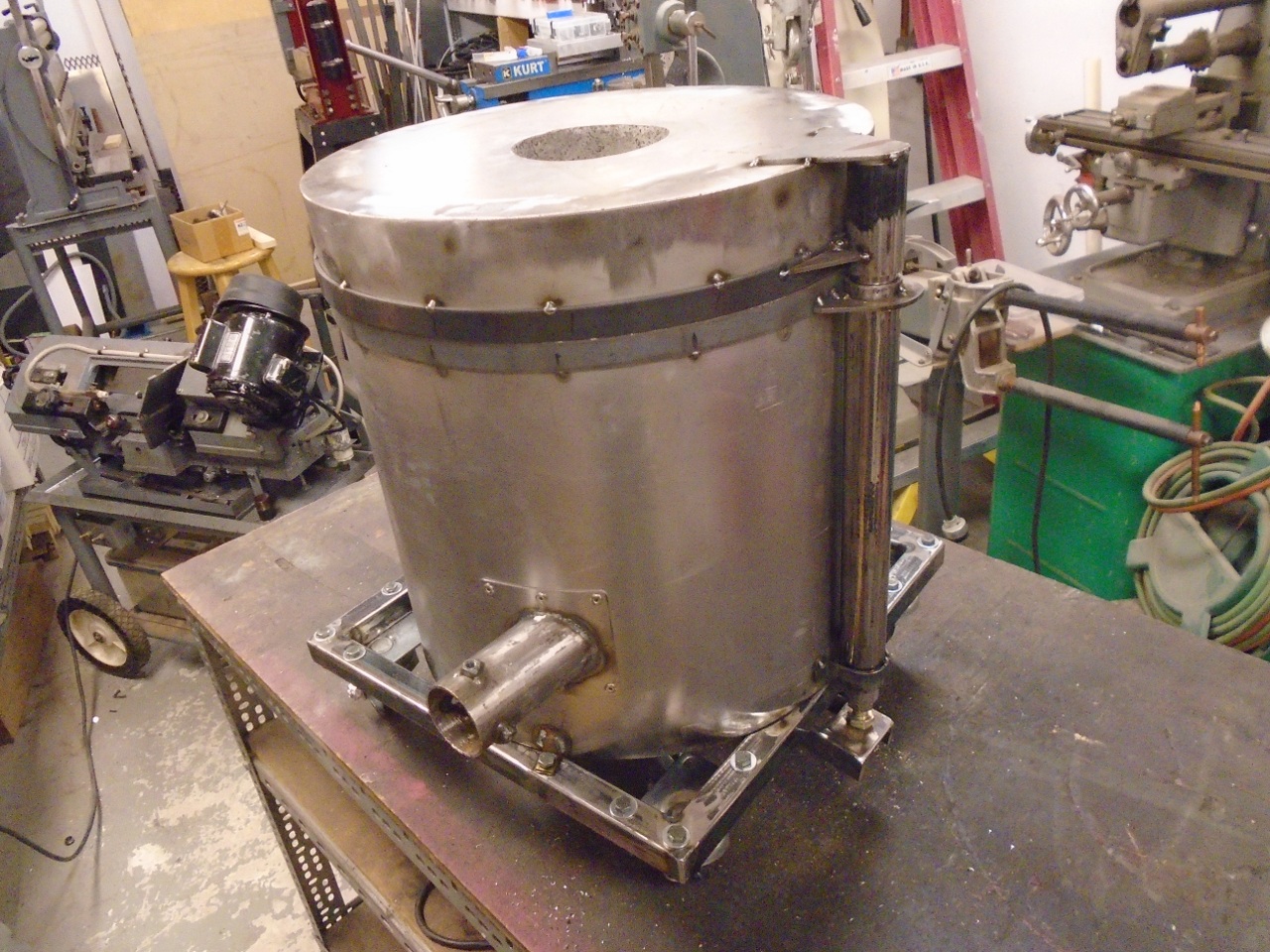
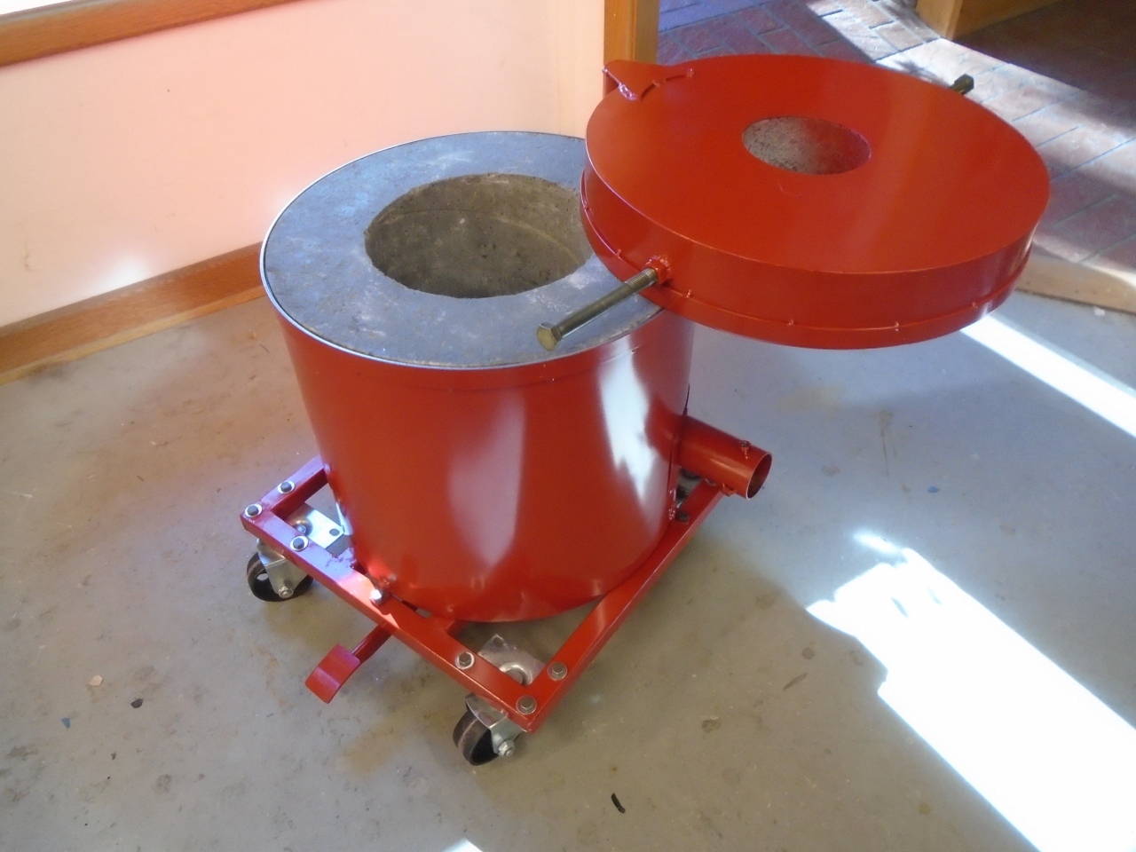
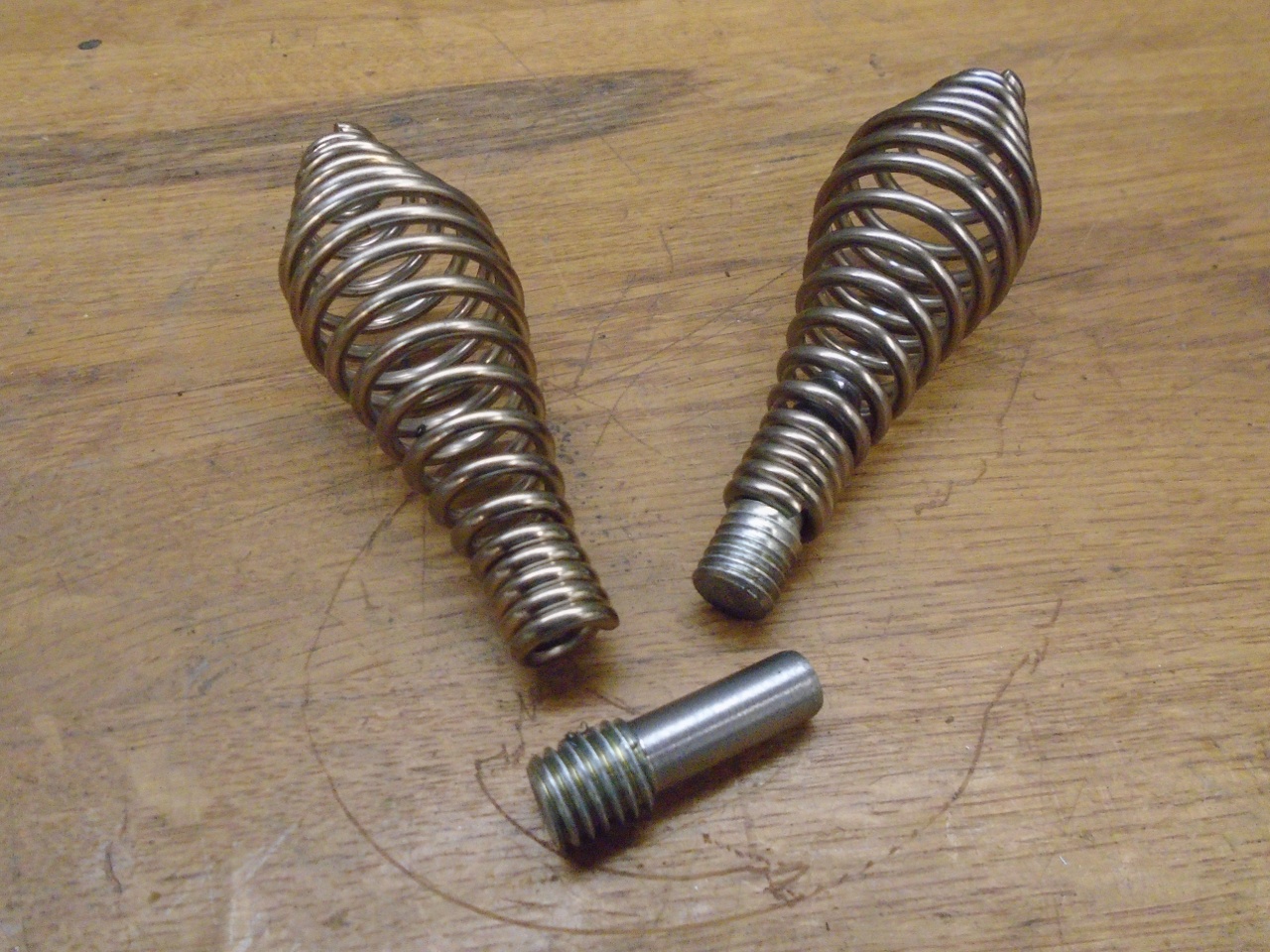
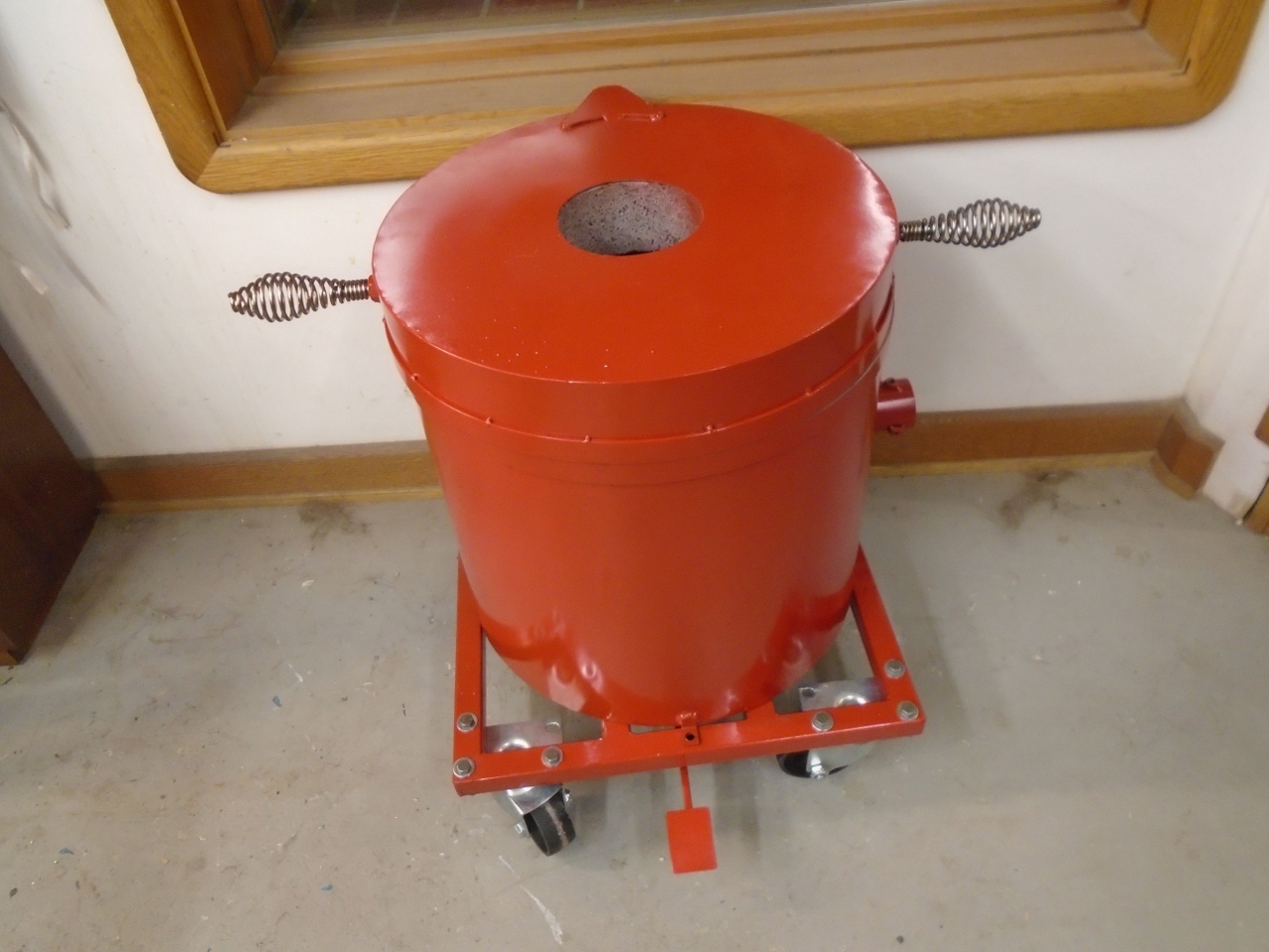
By
this time, the furnace was pretty heavy--around 150 pounds. I
needed some way to make it a little more mobile. I made this
platform and mounted steel wheels on it. Also rigged up the lid
lift mechanism similar to some of those I saw in my research.
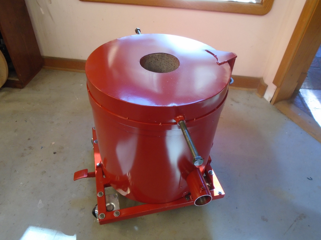
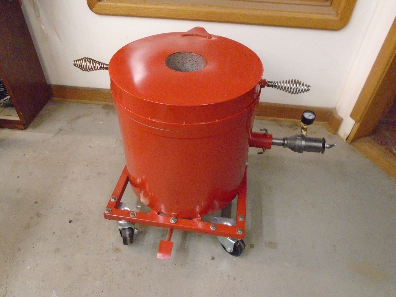
Painted everything a fiery red. I know much of this color will be charred with the first burn.

Now,
with the furnace itself pretty well done, I focused on the burner.
I opted to design the burner for propane. Like the
furnace, there are a lot of resources on the Internet describing DIY
burner construction. I absorbed as much information as I could,
and set out to build my burner. It is a variant of a ubiquitous
Reil burner.
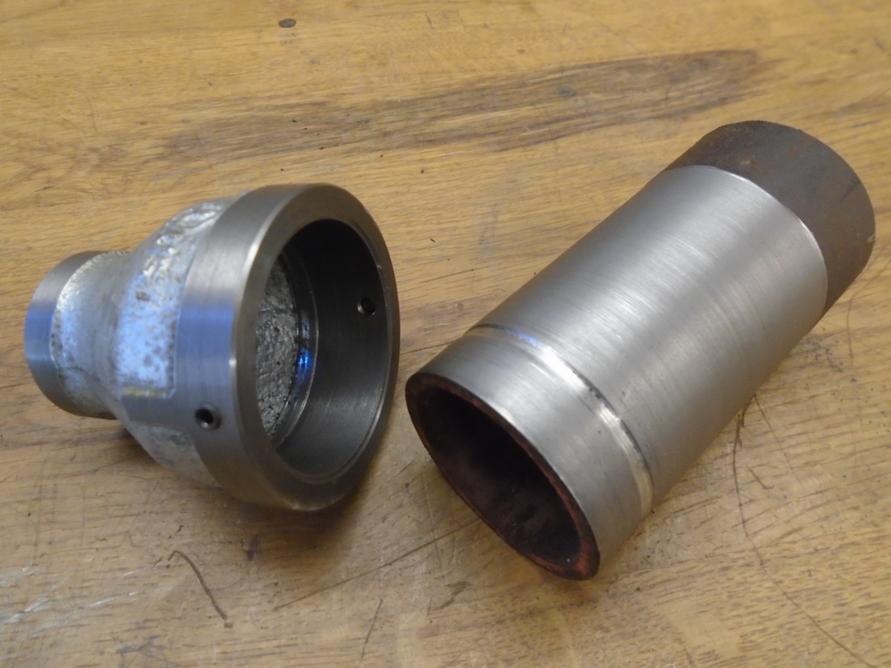
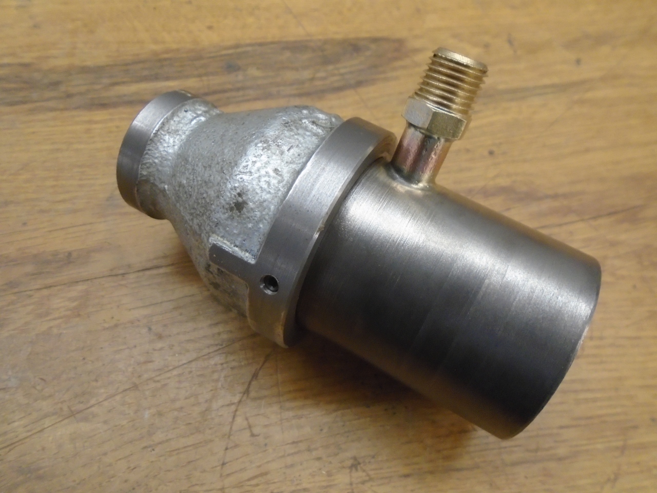
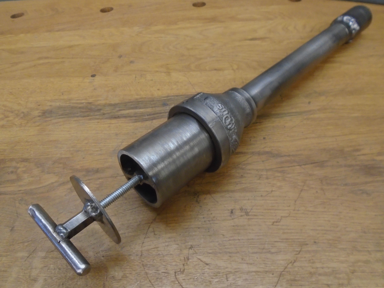
The
burner is basically a venturi arrangement with a provision to inject
propane into the air stream. The venturi is implemented with a
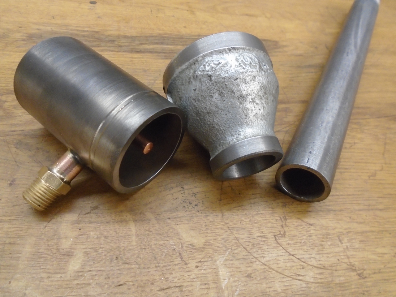
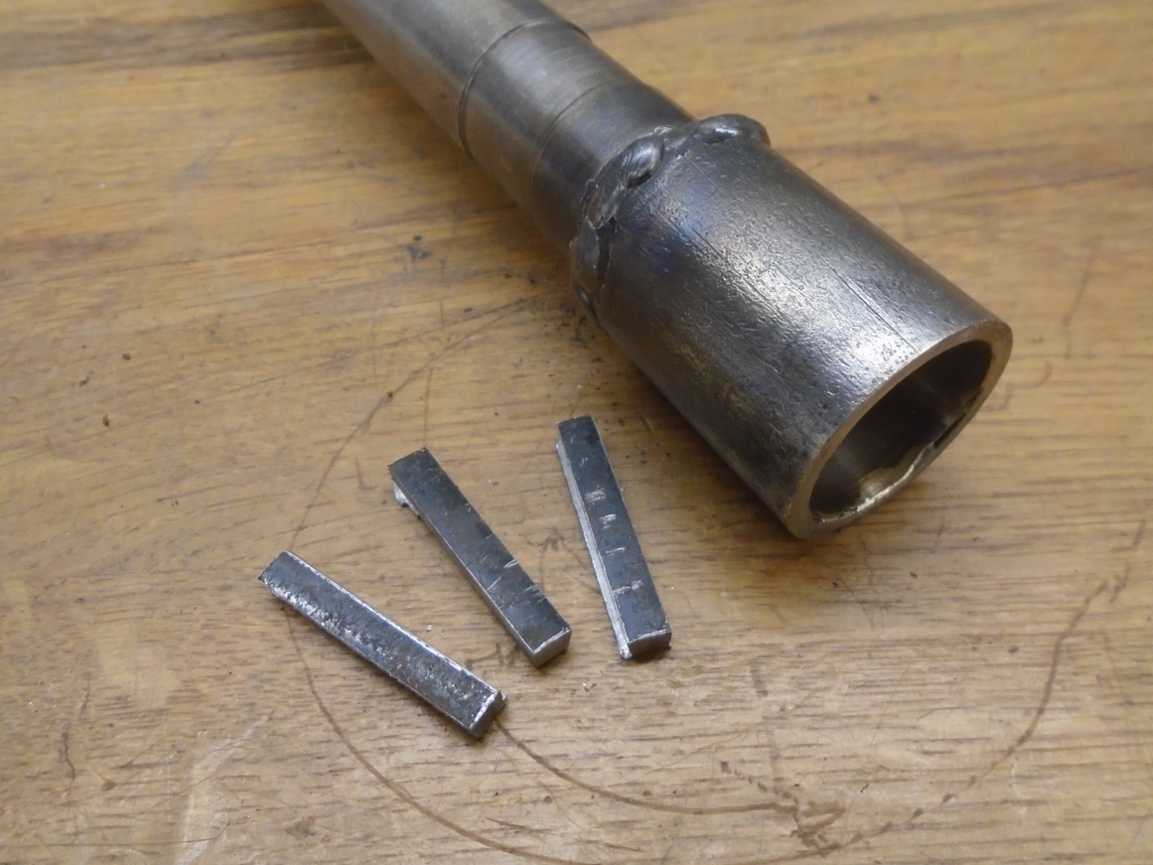
reducer pipe fitting. Rather than screw the fittings together, I
opted to turn the threads out of the reducer, and slip in a short
section of 1-1/2 inch pipe as the air tube. It is retained by a
couple of set screws that seat in a groove.
That
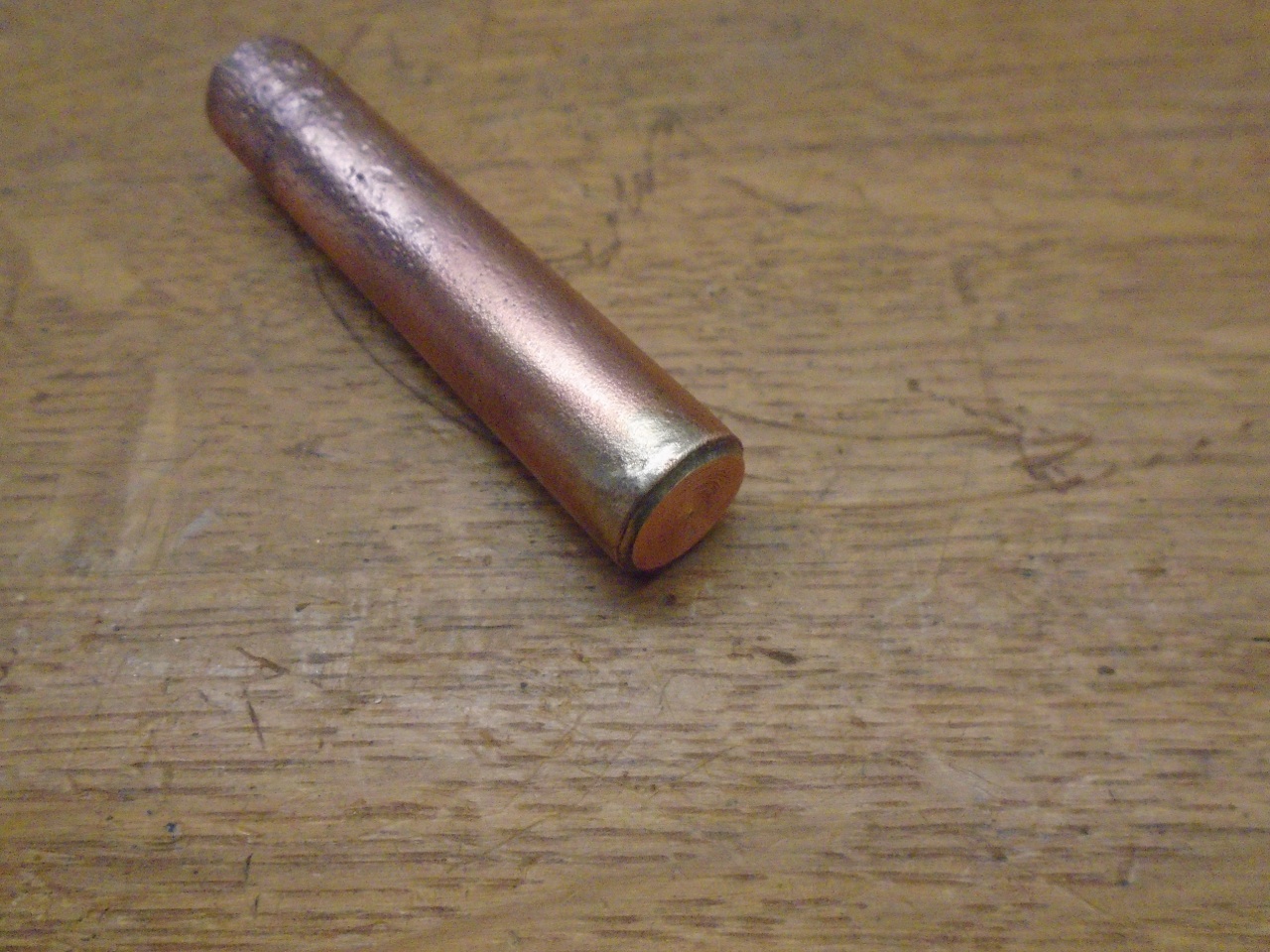
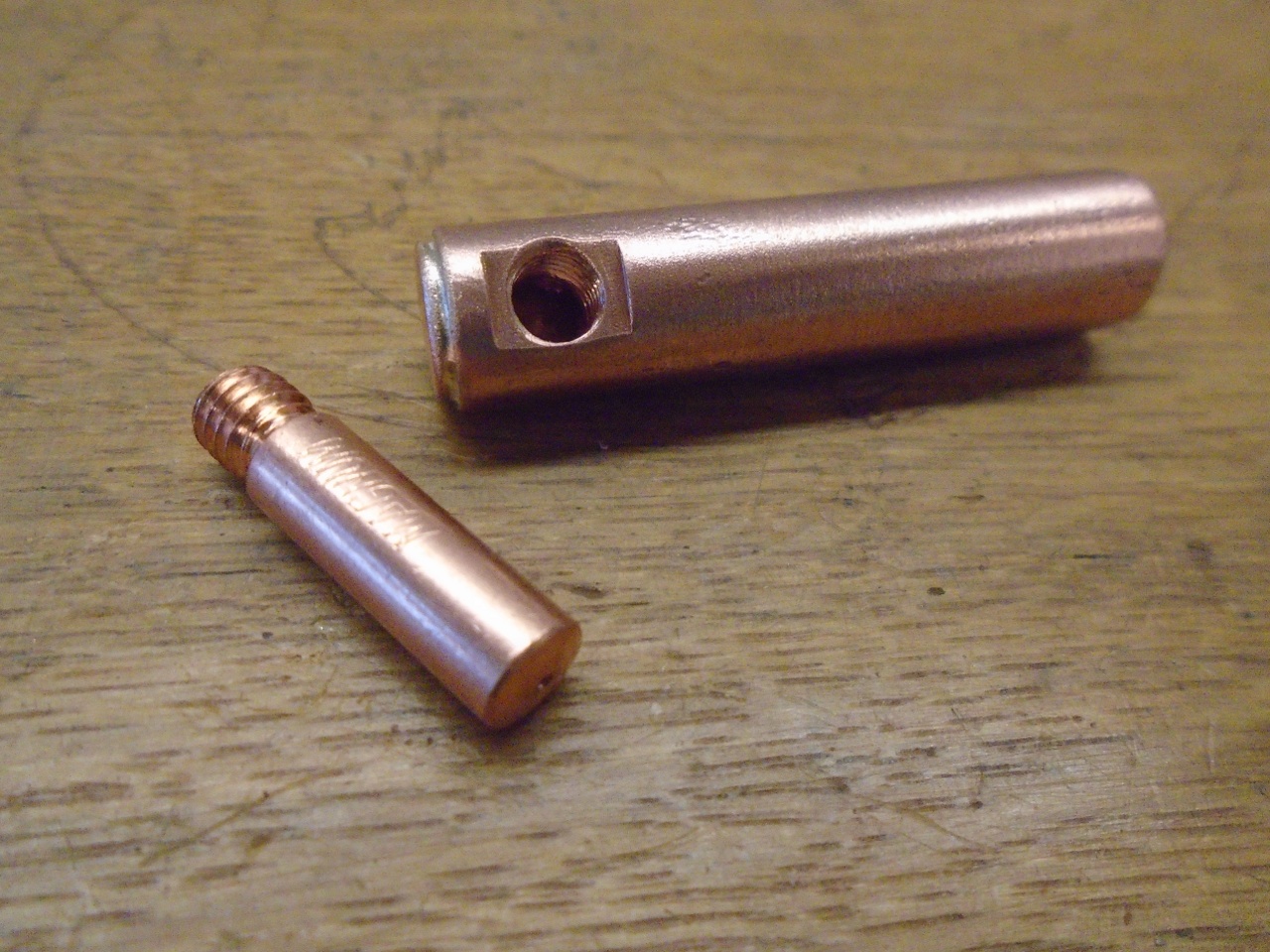
short pipe section holds the propane injector. The feed for the
injector is a short piece of brass pipe with a plug silver brazed into
one end. The plug is shaped as to proivide enough meat on one
side so the injector can be screwed into it. The injector itself is a MIG welding tip.
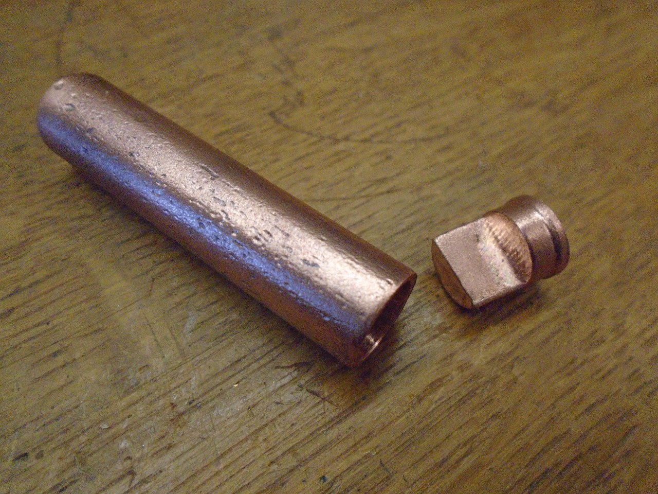
Then a 1/4" NPT fitting was brazed on the other end.
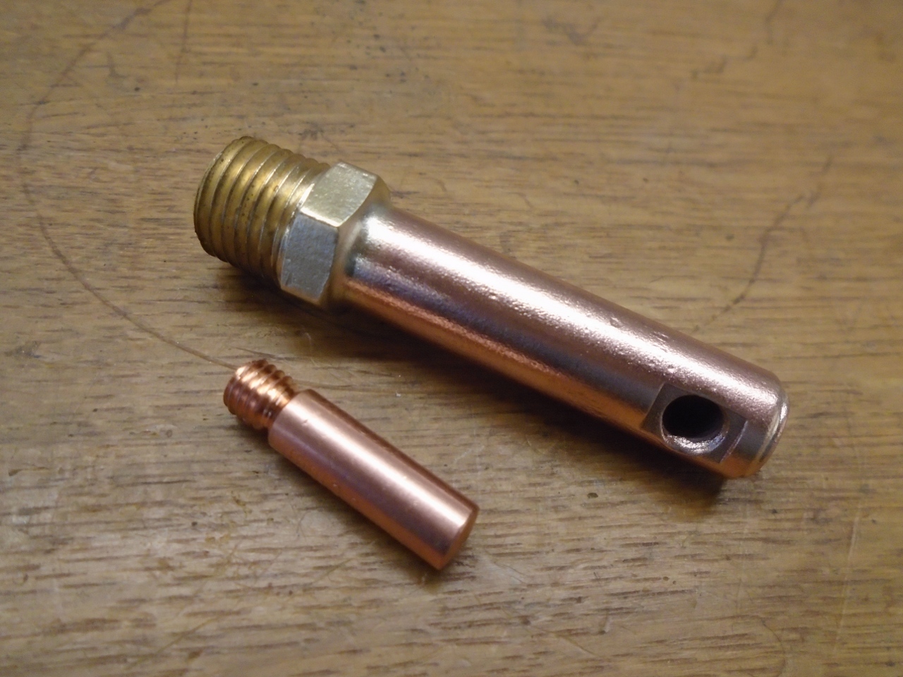
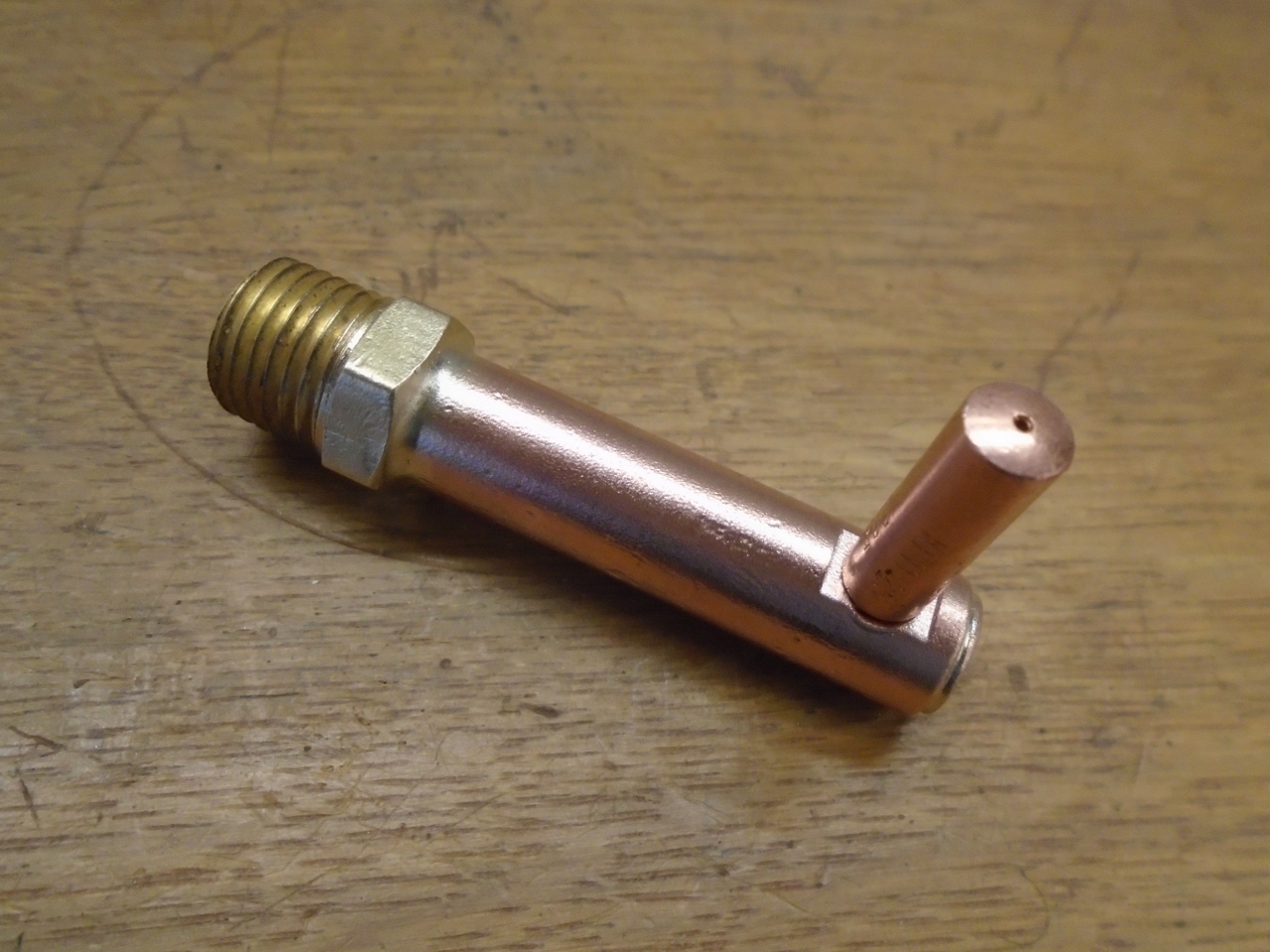
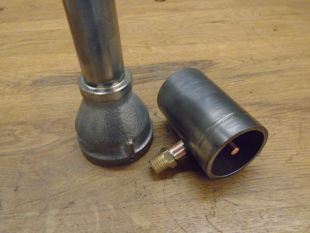
A
hole is drilled in the air tube to accept the injector assembly.
The MDF disc holds the injector centered and aligned for brazing
the gas tube to the air tube.
The MDF was smoking pretty good by the time the brazing was done.
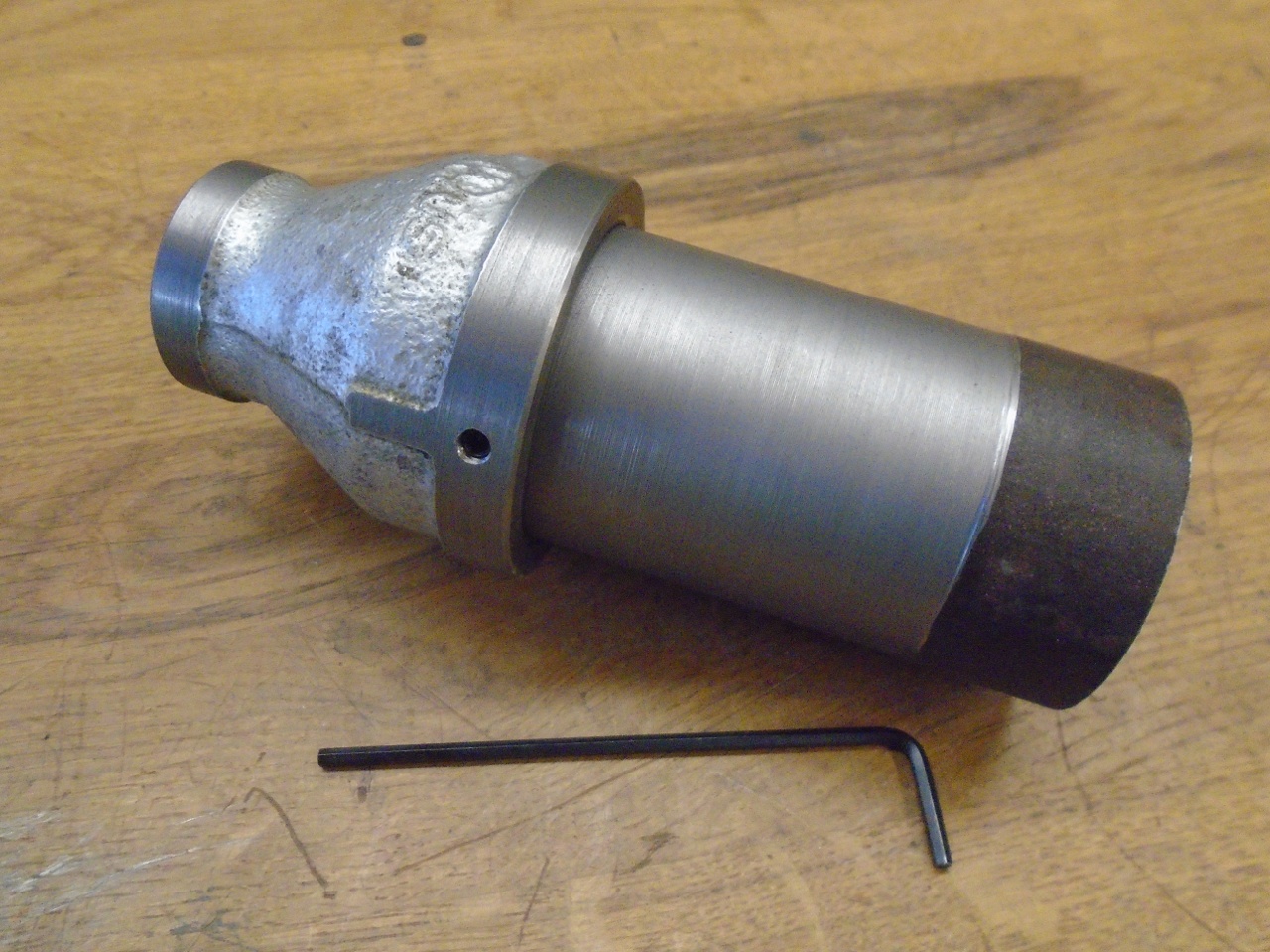
So here is the assembled venturi, air tube, and injector.
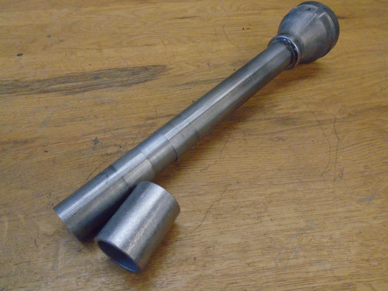
The main extension pipe of the burner was then brazed into the venturi.
Most
DIY burner builders like to have a tapered nozzle at the hot end of the
burner. I accomplished this by brazing a short section of 1" pipe
over the 3/4" pipe of the burner, then turned the inside of the smaller
pipe to a taper. It dawned on me a little later that this end of
the burner probably gets hot enough to melt the silver braze material,
so I went back and welded the nozzle piece on.

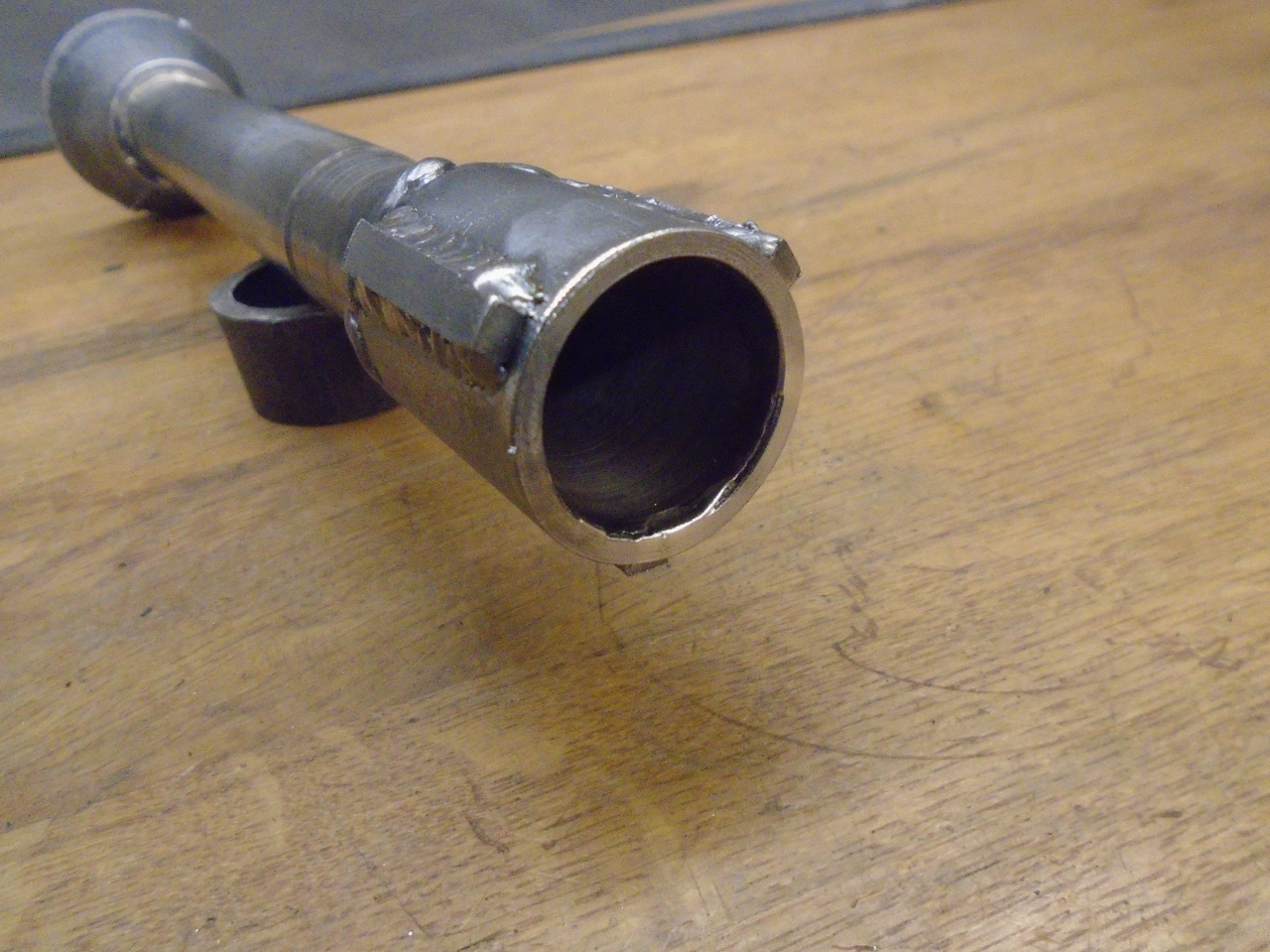
The
last major thing to do on the burner was some provision for a choke to
regulate air flow. There are a lot of good designs out there, but
this is what I landed on. I started with a 1/4-20 threaded
coupler and added a couple of wings to it. I then welded it into
the air tube so the coupler was centered in the bore.
A circular plate welded to a T handle and a threaded rod forms the adjustable choke.
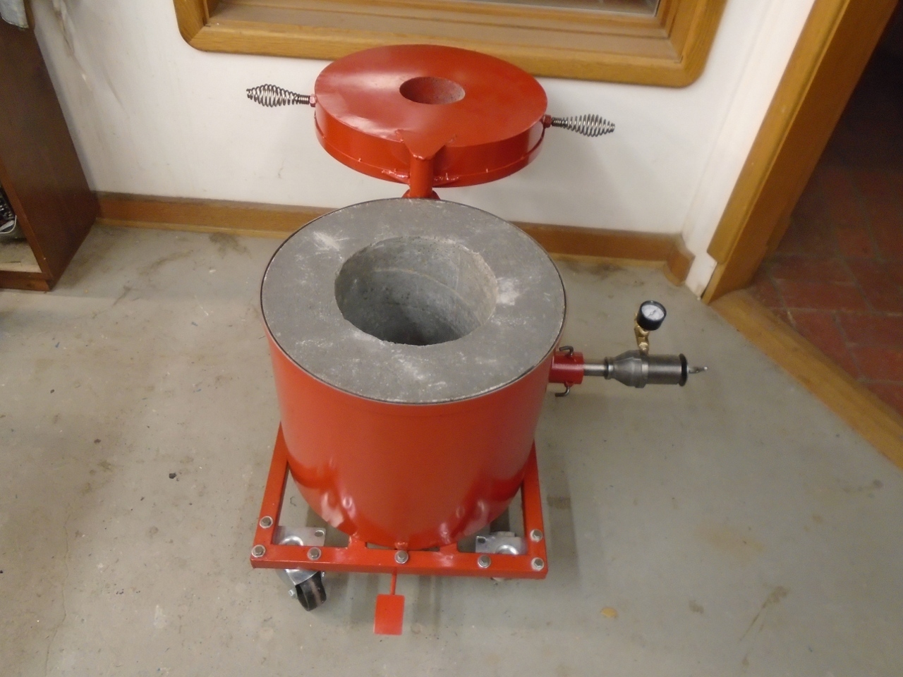
When
I first inserted the burner into the furnace, I noticed that the nozzle
kind of rattled around in the refractory opening, which I made plenty
large to handle a larger burner. To fix this, I added these three
little bosses to the nozzle. They provide a much better fit to
the refractory opening.
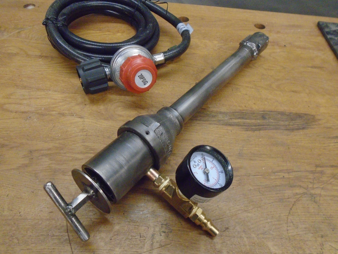
The complete burner assembly:
As a last touch, I mounted a couple of stove handles to the lid.
The furnace is now finished, but I need to wait for better weather to start her up.
Comments to Ed at elhollin1@yahoo.com