A Temporary 4th Axis on the Mill
Ed Hollingsworth
Omaha, Nebraska
So I have this old Triumph motorcycle
I've been working on. After more than 30
years stored in my garage, I thought it deserved a little attention and maybe a
new chance at seeing the open road again. With due consideration, I finally decided not
to do just a casual fix-up—I’d do a complete top-to-bottom rebuild of the bike.
As part of the normal research necessary
with this kind of rejuvenation, I stumbled across an interesting bit of obscure
Triumph lore. Among the old heads who
care about these things, it’s a widely held belief that there was a bit of a
botched redesign of part of the valve train on these machines back in the late
60s. For a few years, some models left the factory with certain features
of the new design missing, and my bike was one of those affected. One of
these missing features was oil grooves on the spindles that hold the valve rocker
arms on the vertical twin pushrod engine. This could lead to poor
lubrication of the pushrod ends and the valve stem tips. Many owners
today who know about this just chalk it up to part of the charm of these old
machines, and live with it.
On the other hand, I had just bought this new (to me) milling machine and,
having told my wife how useful it was going to be, I was looking for a
project to use it on. I decided as part of the rebuild to put oil grooves
on the Triumph's rocker spindles.
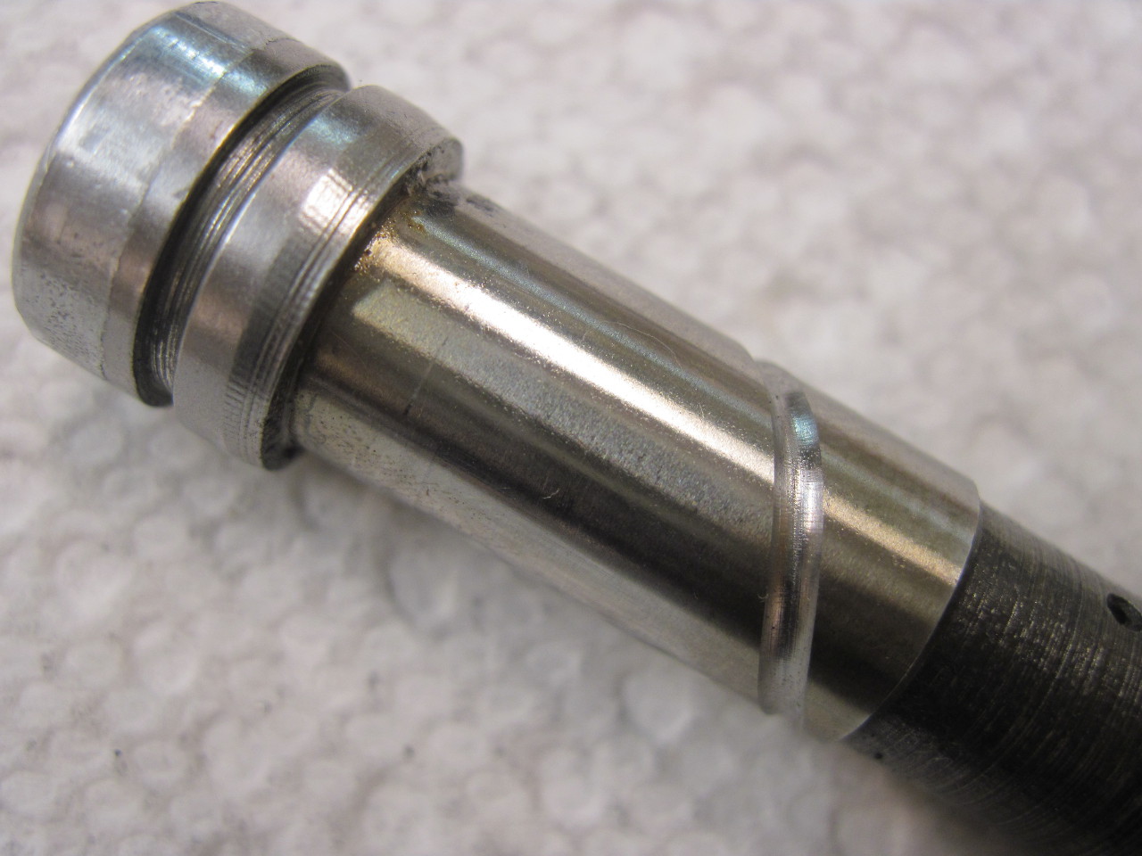
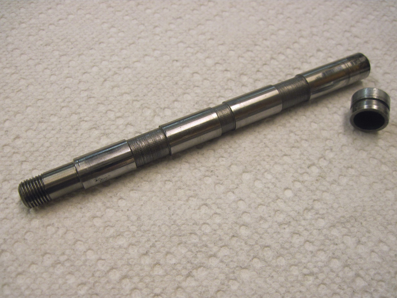 The
pic to the left shows what the 42-year-old spindles look like (click in
this and all other pics to see a larger view). They still
measure within spec, so I can't justify new ones (and new ones don't
have
grooves, either, since the factory never acknowledged the mistake).
The
picture doesn't show them, but the shaft is drilled through its length,
and
there are oil feed holes in each of the three areas of reduced
diameter. Oil is
fed into the center reduced area, and exits the other two, which are in
the
center of each rocker arm. The working surfaces are 7/16"
diameter.
The
pic to the left shows what the 42-year-old spindles look like (click in
this and all other pics to see a larger view). They still
measure within spec, so I can't justify new ones (and new ones don't
have
grooves, either, since the factory never acknowledged the mistake).
The
picture doesn't show them, but the shaft is drilled through its length,
and
there are oil feed holes in each of the three areas of reduced
diameter. Oil is
fed into the center reduced area, and exits the other two, which are in
the
center of each rocker arm. The working surfaces are 7/16"
diameter.
Judging from later model years, it appears that Triumph
had intended spiral grooves on the spindles, so that’s what I decided to do. The
problem is this would require a 4th axis in the mill, which it didn't have.
The rotation of the fourth axis would have to be coordinated with travel
down the length of the shaft. Since mine
is a manual machine, I’d have to do this mechanically.
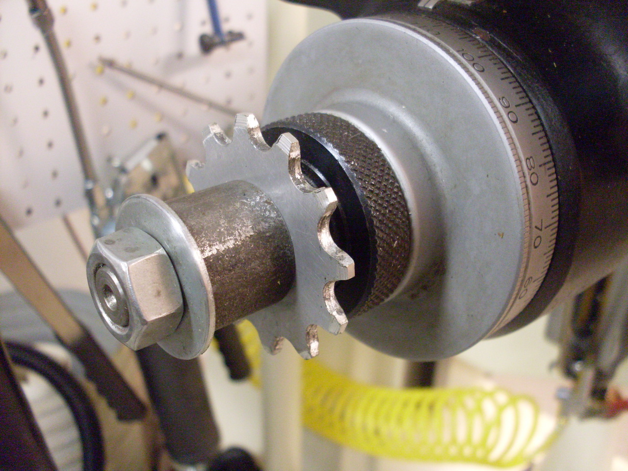
My solution was to take the 4th axis drive from the X lead screw with a
chain and sprocket arrangement. I figured that the sprocket ratio had to
be between 3 and 3.5:1 to get one complete spiral on each spindle bearing
surface. This matched the later Triumph parts. I decided to just use
1/8" bicycle chain because it was cheap and easy to get. I looked for the
right combination of commercial chain sprockets, and found them pretty spendy
for what was probably going to be a one-time use. A little thought and
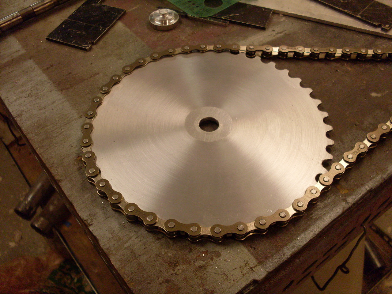
research encouraged me to just make them myself. I decided to use
sprockets with 12 and 40 teeth, which gives a good ratio and reasonable sizes.
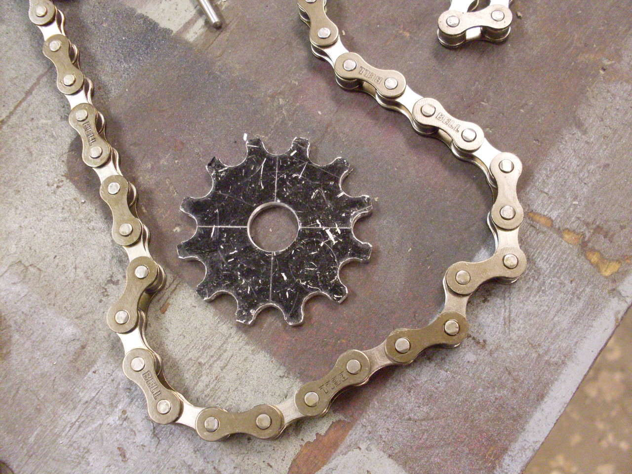
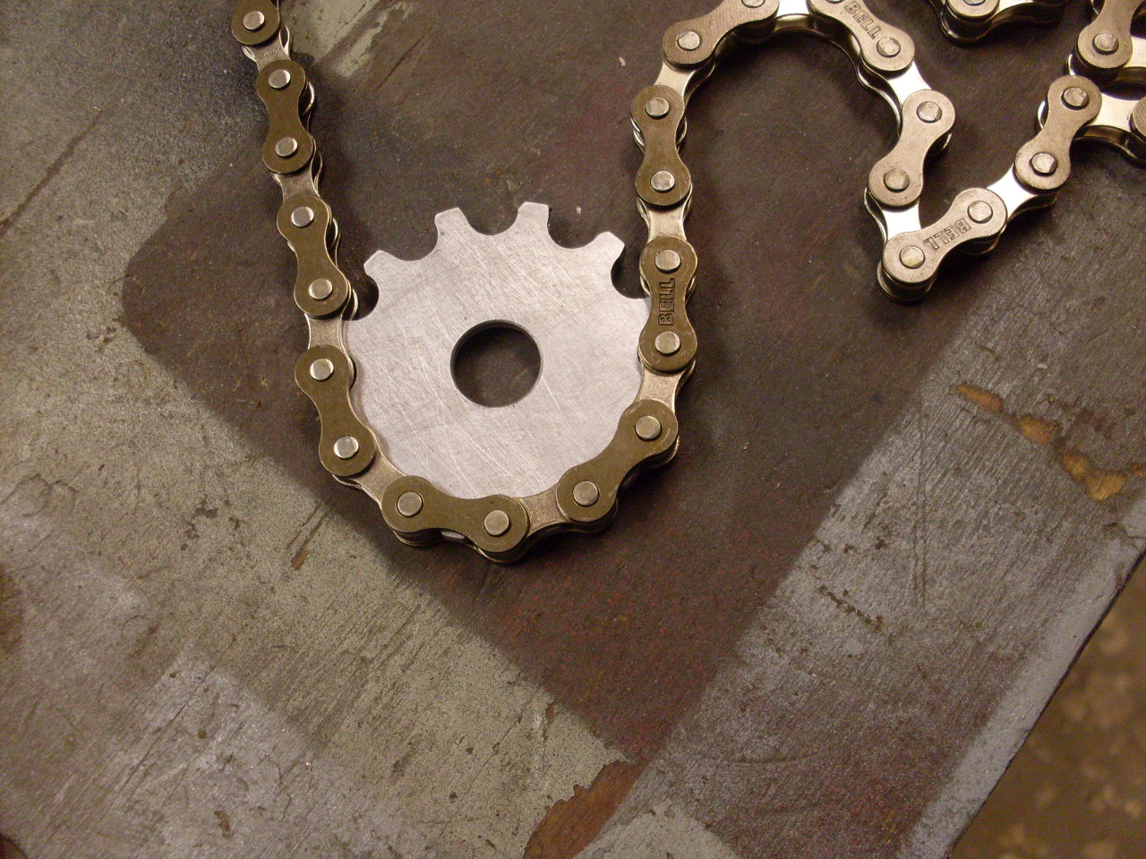
Though there are fairly complex specifications for the tooth shapes on
chain sprockets, the quick and dirty way to do it is to drill holes to fit the
chain rollers (0.300" in this case), spaced around a pitch circle with
spacing to match the chain pitch (0.500"). The teeth are then shaped
to avoid interfering with the rollers as they enter or leave the seats.
Calculating the pitch diameter from the chain pitch and number of teeth
is a pretty basic trigonometry problem (see Sidebar 1)..
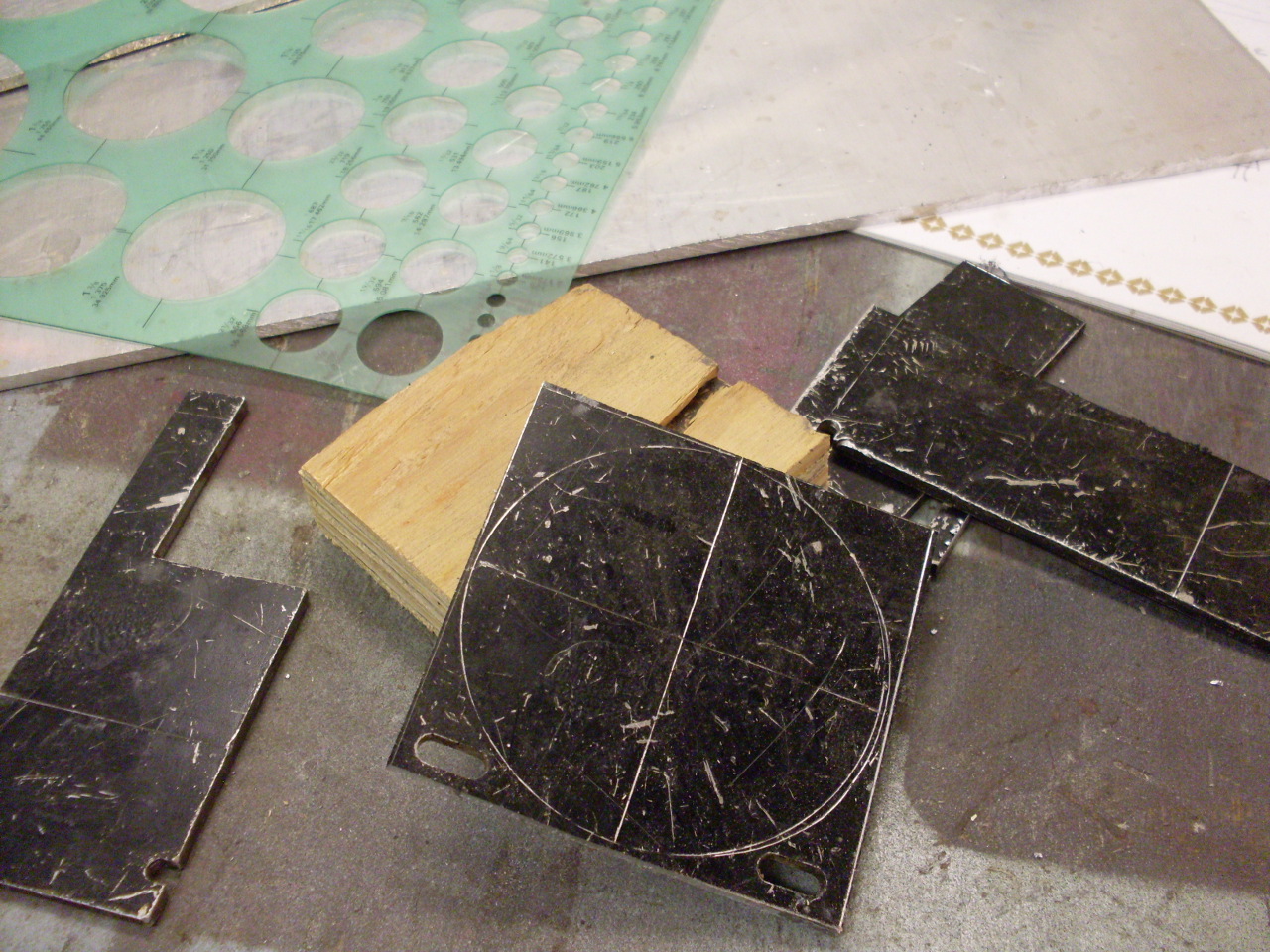
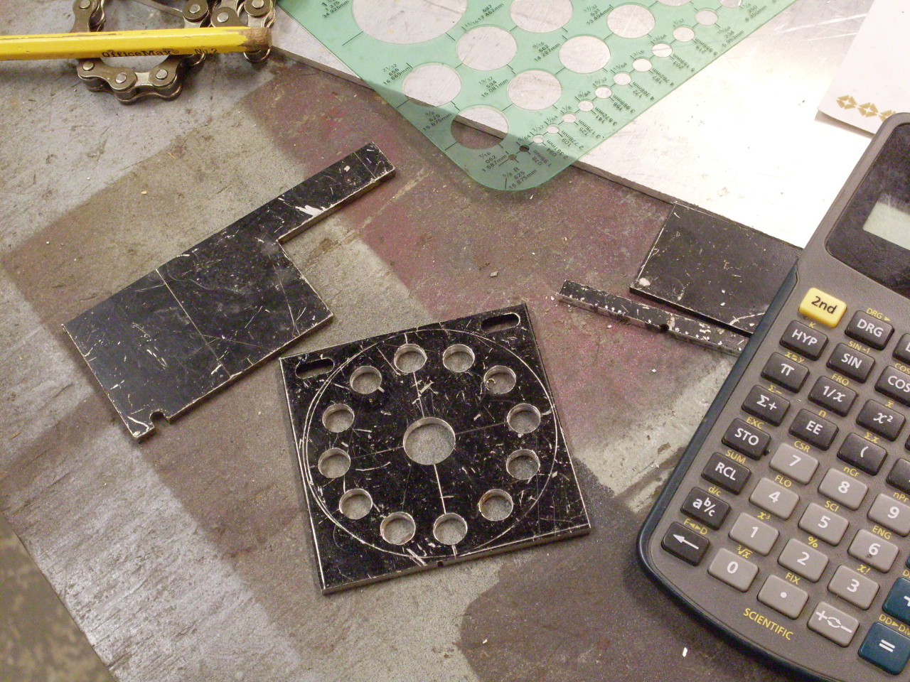
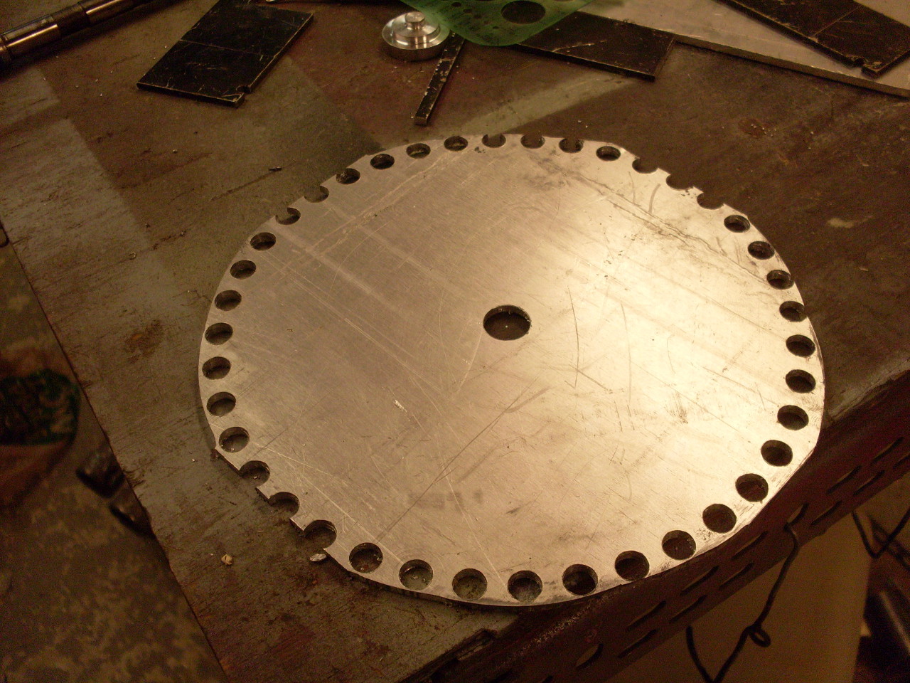
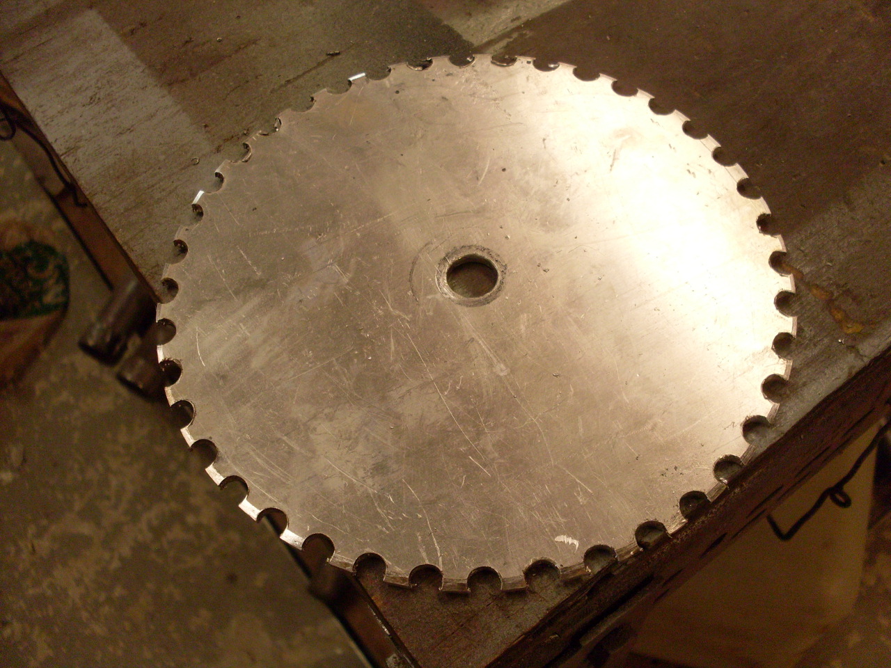
I started with 1/8" aluminum sheet, cut it to rough square
size, and put it into the mill vice. I used my DRO's circle pattern
feature to mark the hole positions around the pitch circle with a spot drill,
then came back around and drilled them with a 7.8 mm drill (0.307"--the
specs say to have the seat diameter slightly larger than the roller). The following pics show the stages of
the process for the small and the big sprocket.

I filed a keyway in the small sprocket and mounted it to
the left end of the X lead screw of the mill table after taking the handle off.


I made a hub on the lathe so I
could mount the big sprocket on a ½” drill rod shaft. The shaft was about 18 inches long to bring
it over near the center of the 49 inch mill table. I used a piece of ½” black iron pipe to carry
the shaft. I bored the ends of the pipe
to accept a 1/2” bronze bushing in each end.
To make sure the bushes were collinear enough not to bind on the shaft,
I made the bores a little roomier than normal, and super glued the bushes into
the pipe with the shaft in place.
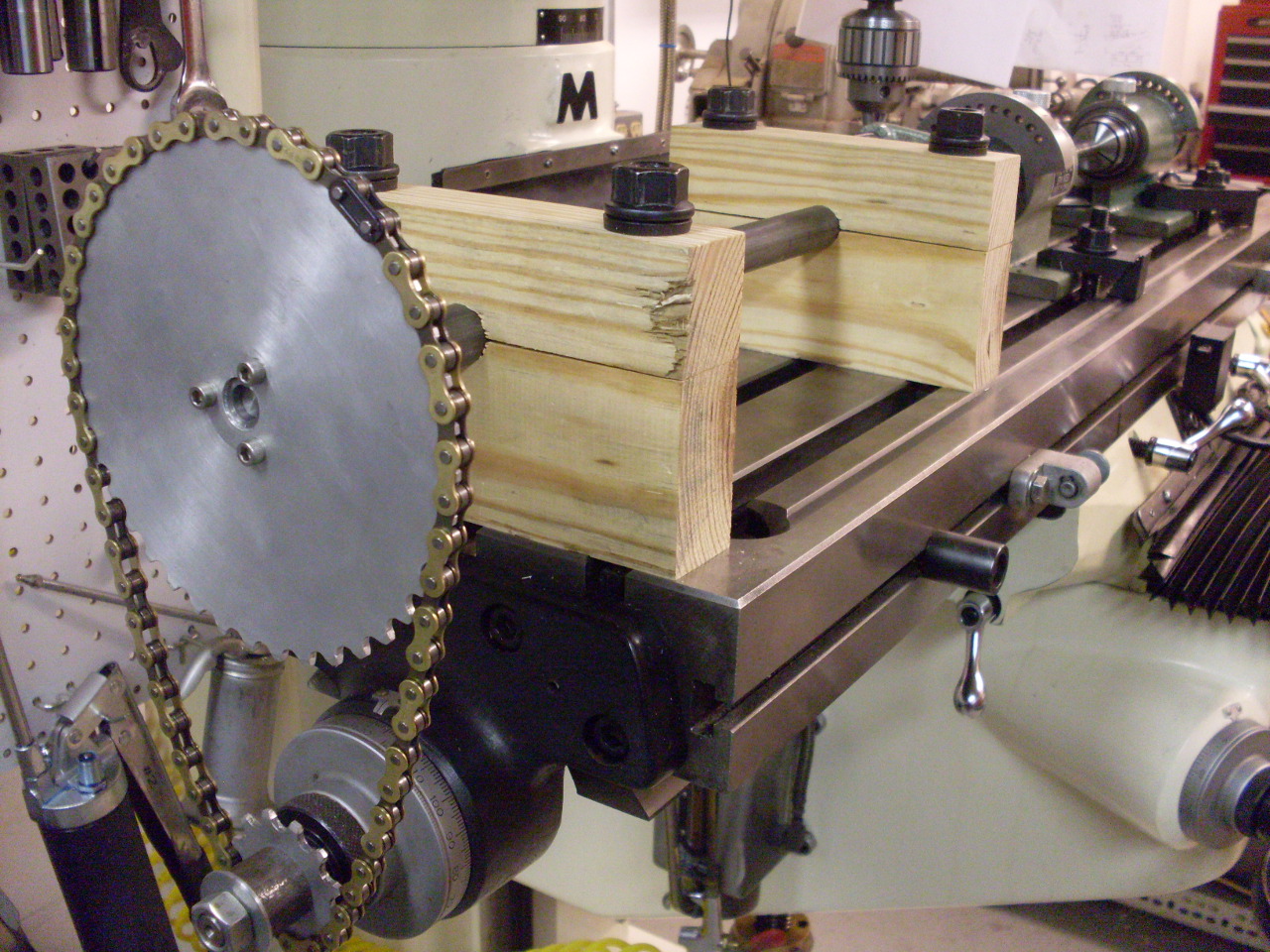
I then fashioned two pillow blocks made out of wood to hold the shaft
assembly at the right height above the table (I started as a woodworker—it’s
hard to change old habits).
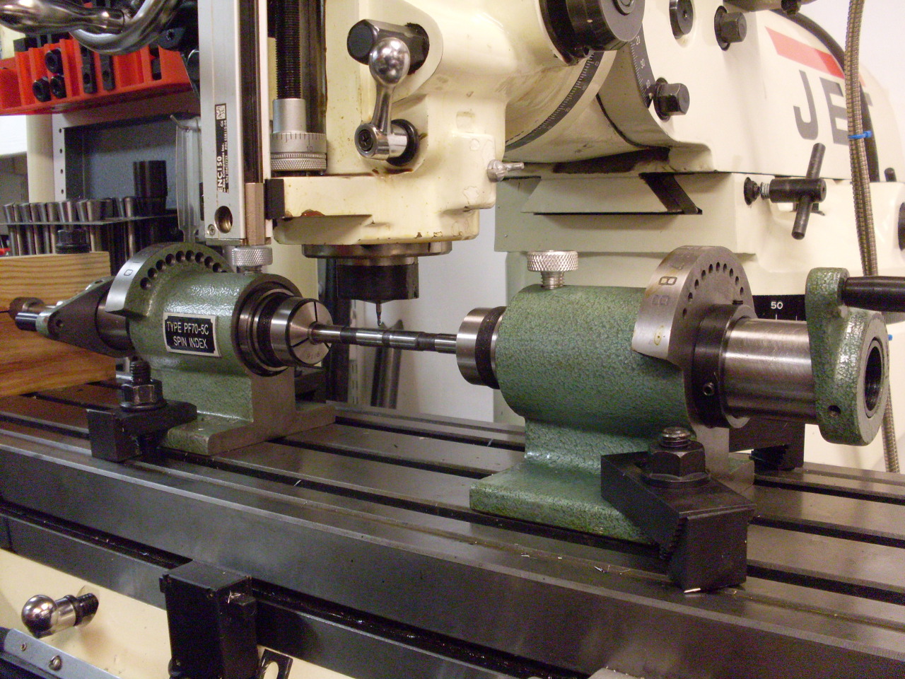
The work (the rocker spindle) is held at each end by one
of those ubiquitous PF-70 spin indexers using 5C collets--3/8" at one end,
and 9/16" at the other.
This is what determined the height of the drive shaft above the table. I
got better clearance on the indexers by taking them apart and reassembling them
backwards. I also took off the index disks. I was pretty amazed
that the height of the work varied by only about 0.002” from end to end.
I was prepared to have to skim the bottom surface of one of the indexers,
but it wasn't necessary.
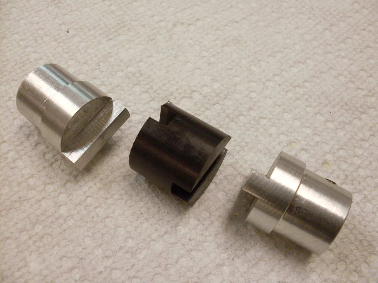
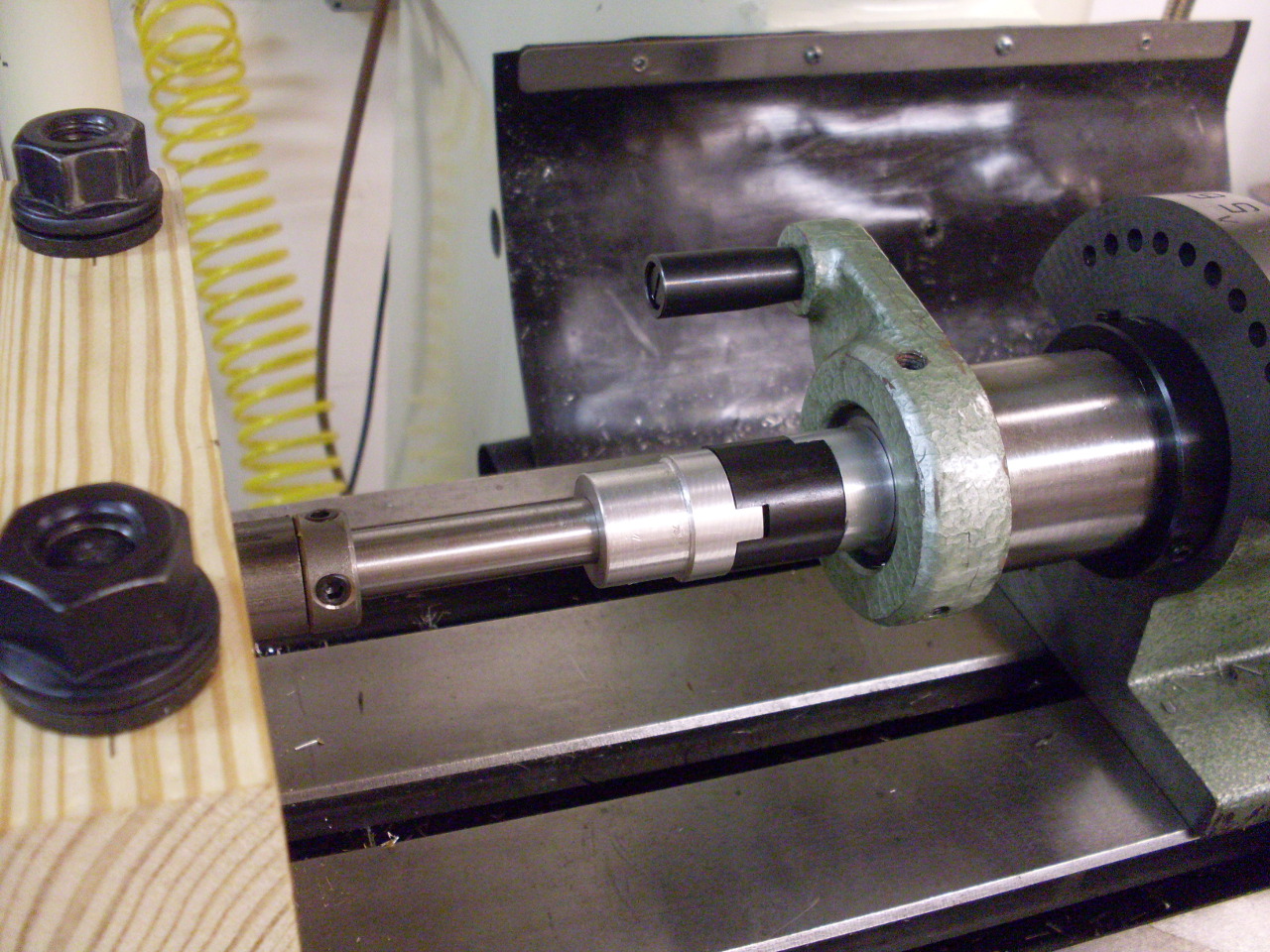 To
avoid having to be too persnickety about alignment, I
made an "Oldham Coupling" to tie the drive shaft to the left indexer.
The coupling accommodates some shaft misalignment. The
center part of the coupling is Nylon for a smoother
action. One end of the coupling is turned for a snug fit inside
the drawbar
of the left indexer and is fastened with a couple of set screws.
To
avoid having to be too persnickety about alignment, I
made an "Oldham Coupling" to tie the drive shaft to the left indexer.
The coupling accommodates some shaft misalignment. The
center part of the coupling is Nylon for a smoother
action. One end of the coupling is turned for a snug fit inside
the drawbar
of the left indexer and is fastened with a couple of set screws.
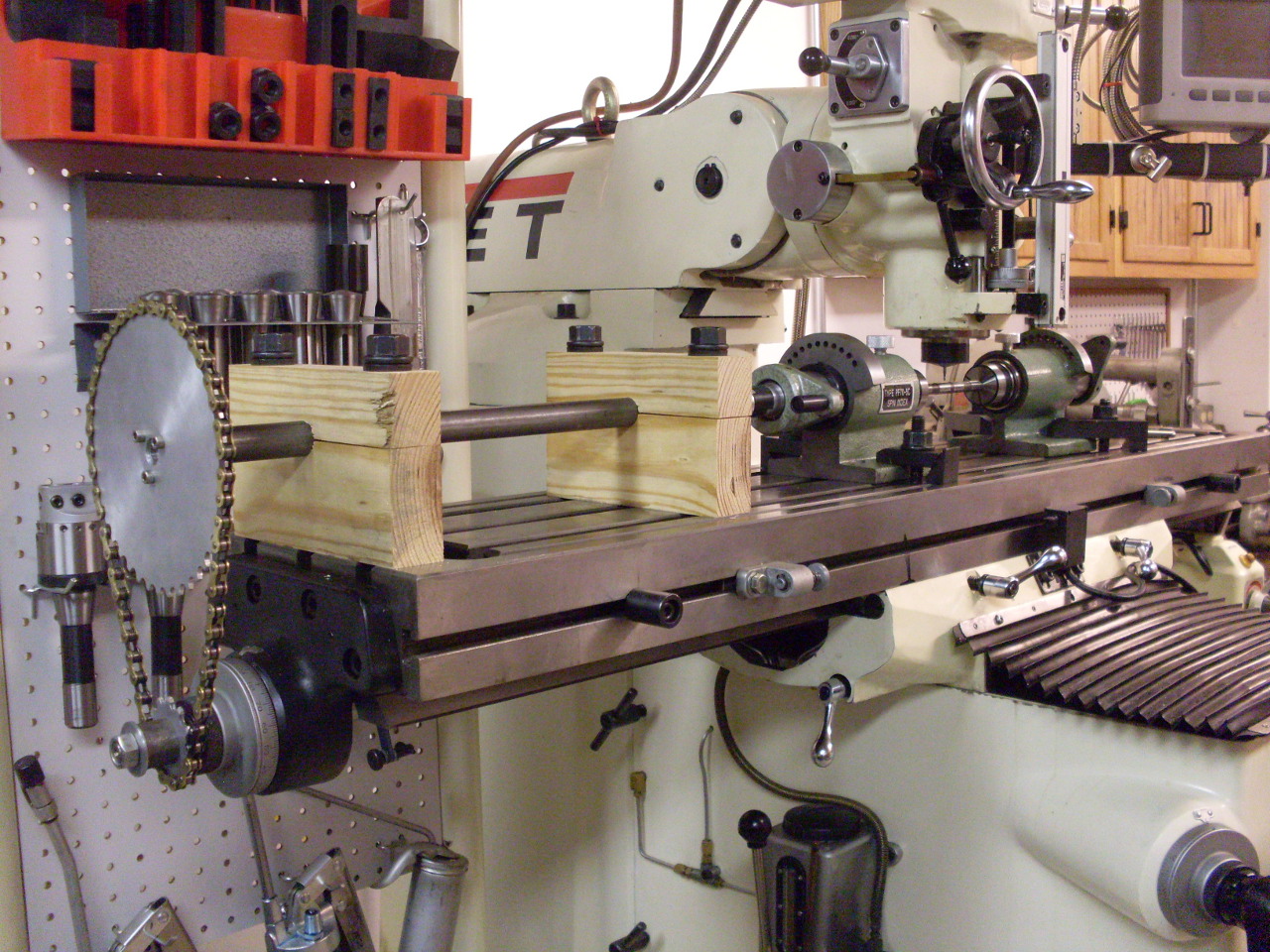
I indicated the work to make it true with the X travel, and tightened
everything down. Here is the
entire setup.
Measuring from later year parts, the grooves needed to be about 0.016"
deep and about 0.065" wide. A little more trig (See Sidebar 2) showed that a
5/64" ball end mill should do the trick, so I ordered a couple of solid
carbide units. I wasn't sure how hard the shaft was or if HSS cutters
would have a problem.
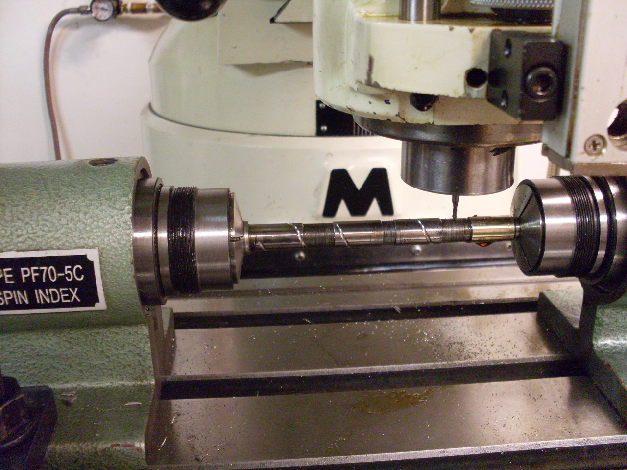
It turned out to be pretty simple to do the actual cuts. I positioned the cutter directly above the
centerline of the work, and, starting in the reduced diameter
areas, fed slowly by hand using the highest speed my mill would do (4200
RPM). The last pic shows the resulting
groove.
After all this, my bike has better lubrication to its
valve train, I've got some new skills and experience, some tooling vendors have
some more money, and my wife thinks I did something useful. Everybody's
happy.
Sidebar 1: Calculating Pitch Diameter
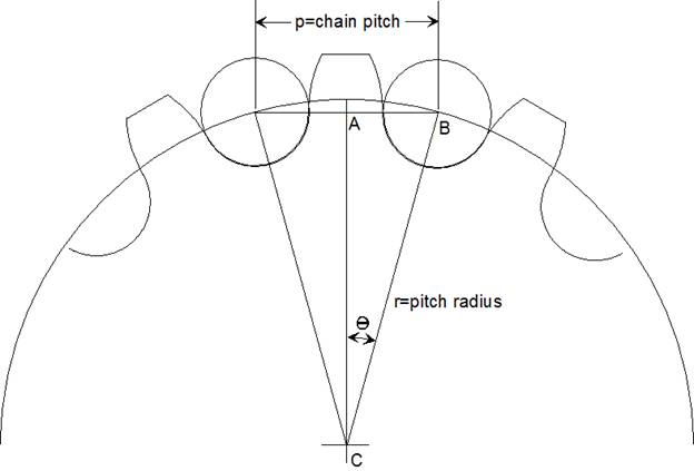
To find sprocket
pitch radius when chain pitch and number of teeth are known:
 is one half of the angle between teeth, so, if
n is the number of teeth on the sprocket,
is one half of the angle between teeth, so, if
n is the number of teeth on the sprocket,
 .
.
Triangle ABC is a right triangle with AB
equal to half of the chain pitch, and BC equal to the unknown pitch
radius. To find the pitch radius:
 .
.
The first formula gives the angle in
degrees, so make sure the calculator is set appropriately for the second
formula.
For larger sprockets, a shortcut formula
may be used. The circumference of the
pitch circle can be approximated by multiplying the number of teeth by the
chain pitch, and the pitch radius comes by dividing that by 2π.
 .
.
For sprockets with more than 12 teeth, the
error of the approximate formula is less than 1%.
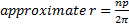
Sidebar 2: Calculating cutter Radius:
What
size ball end mill is required to make a groove of known depth and width?
First, we’ll assume that the groove is
being cut in a flat surface instead on the surface of a shaft. This vastly simplifies the math, and the
error is small.
Triangle ABC is a right triangle with CB
equal to the radius of the ball end mill, BA equal to half of the groove width,
and AC equal to the mill radius minus the groove depth. Using the Pythagorean formula for right
triangles,
 ,
,
or

A little algebra gives:
 .
.
The nominal size of the cutter (its
diameter) would be twice the radius:
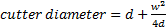 .
.