November 11, 2012
[Click on the pics for a better view]
A Temporary 4th Axis to Cut Spiral Grooves.
So I have this old Triumph motorcycle
I've been working on, and among the old heads that follow such things,
there is a widespread opinion that there was a bit of a botched
redesign of part of the valve train in the late 60s. Some
elements of the redesign didn't get implemented by the factory on some
models for a time, and this resulted in some bikes getting out with a
hybrid of the old and new designs. One of the elements left out
on some bikes was oil grooves on the rocker arm spindles. This
could lead to poor lubrication of the pushrod ends and the valve stem
tips. Many owners today who know about this just chalk it up to
part of the charm of these old machines, and live with it.
On
the other hand, I just got this new (to me) milling machine and, having
told my wife how useful it was going to be, I was looking for a
project to use it on. I decided to put spiral oil grooves on the
Triumph's rocker spindles.
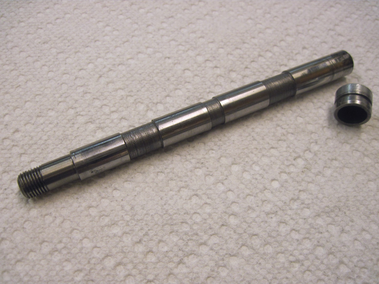
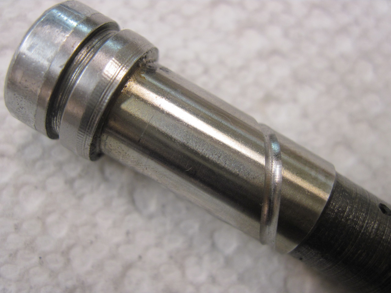
This
is what the 42-year-old spindles look like. They still measure
within spec, so I can't justify new ones (and new ones don't have
grooves, either, since the factory never acknowledged the mistake).
The picture doesn't show them, but the shaft is drilled through
it's length, and there are oil feed holes in each of the three areas of
reduced diameter. Oil is fed into the center hole, and exits the other
two, which are in the center of each rocker arm. The working
surfaces are 7/16" diameter.
On
later models Triumph used both straight and spiral grooves, but I
really wanted spiral grooves, as much for the challenge as anything
else. The problem is this would require a 4th axis in the mill,
which it didn't have. The rotation of the fourth axis would have
to be coordinated with travel down the length of the shaft.
My
solution was to take the 4th axis drive from the X lead screw by a
chain drive. I figured that the ratio had to be between 3 and
3.5:1 to get one complete spiral on each spindle bearing surface.
This matched the later Triumph parts. I decided to
just use 1/8" bicycle chain beecause it was cheap and easy to get.
I looked for chain sprockets, and found them pretty spendy for
what was probably going to be a one-time use. A little thought
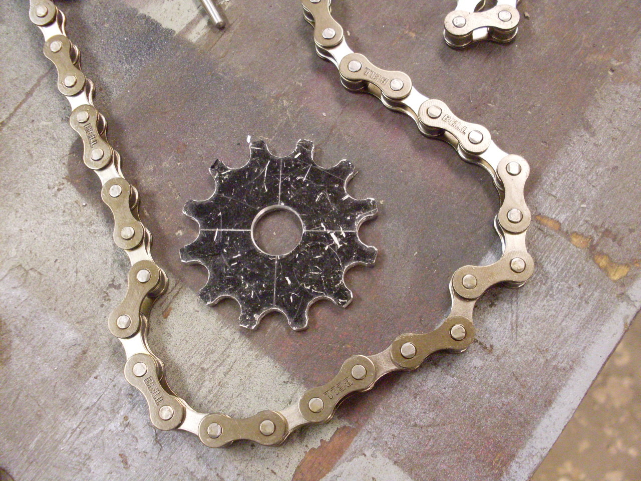
and research encouraged me to just make them myself. I
decided to use sprockets with 12 and 40 teeth. This gives a good
ratio and reasonable sizes. Though there are fairly complex
specifications for the tooth shapes on chain sprockets, the quick and
dirty way to do it is to drill holes to fit the chain rollers (0.300"
in this case), spaced around a pitch circle with spacing to match the
chain pitch (0.500"). The teeth are then shaped to avoid
interfering with the rollers as they enter or leave the seats.
Calculating the pitch diameter from the chain pitch and number of
teeth is a pretty basic trigonometry problem.
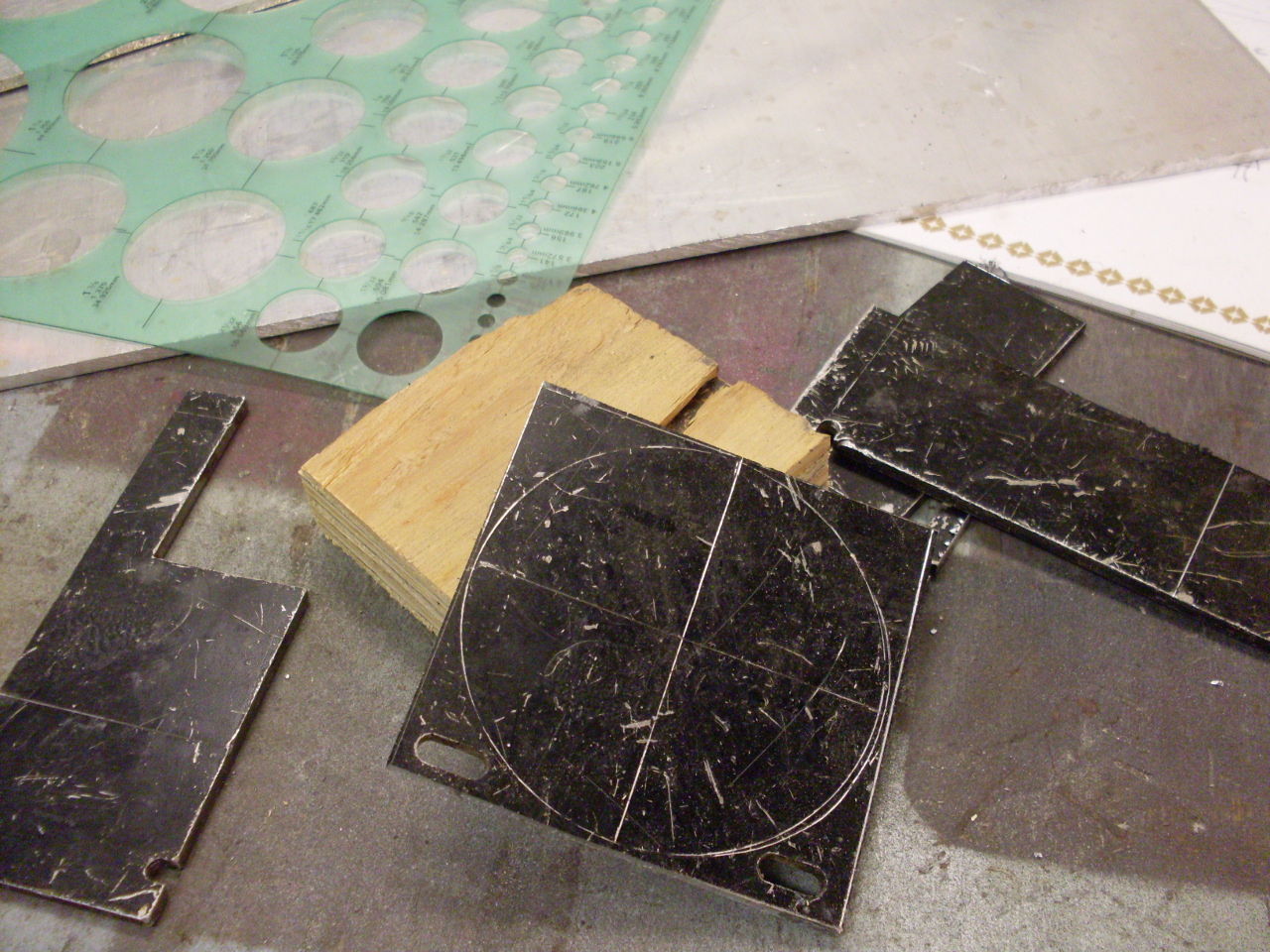
I
started with 1/8" aluminum sheet, cut it to rough square size,
and put into the mill. I used my DRO's circle pattern feature to
mark the hole positions around the pitch circle with a spot drill, then
came back around and drilled them with a 7.8 mm drill (0.307"--the
specs say to have the seat diameter slightly larger than the roller).


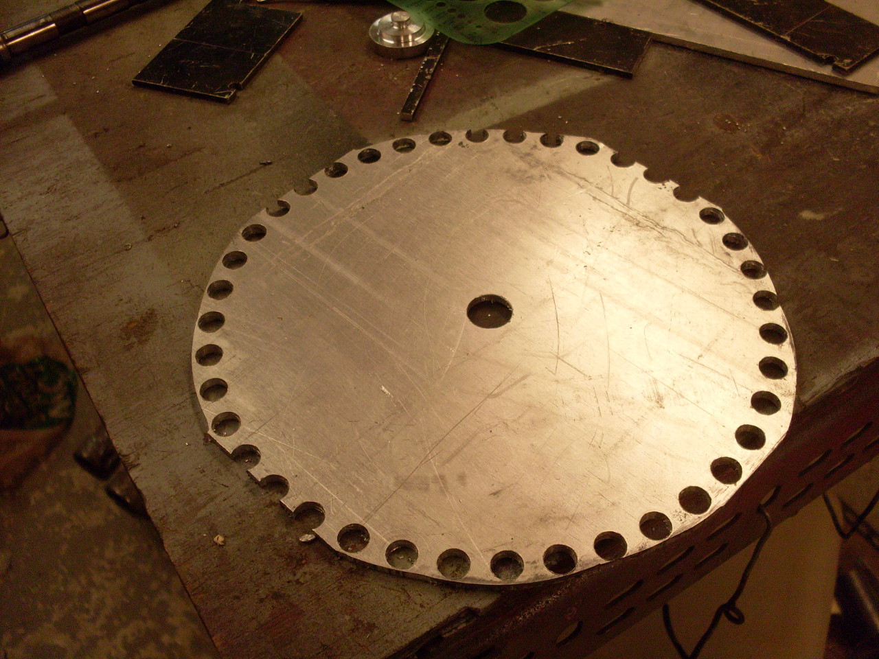
The big sprocket was done the same way:
I
put a keyway in the small sprocket and mounted it to the left end of
the X lead screw of the mill table after taking the handle off:

The big sprocket got a hub so I could mount it to a 1/2" drill rod shaft:


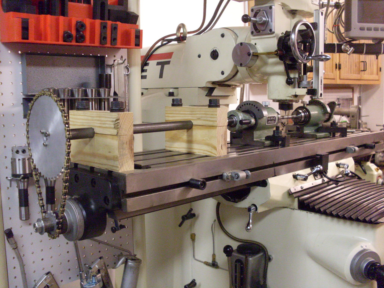
I
then took a length of 1/2" black iron pipe, bored out the
ends, inserted a 1/2" oilite bushing in each end, and slid the
drill rod shaft into it.
The
shaft got mounted in two wood pillow blocks at the right height.
( I started out life as a woodworker. It's hard to change
old habits):

To
avoid having to be persnickety about alignment, I made an "Oldham
Coupling" to tie the shaft to the fixtures that will hold the work.
The coupling accomodates some shaft misalignment.
The center part of the coupling is Nylon. One end of the
coupling is fastened into the drawbar of one of the indexers with set screws.

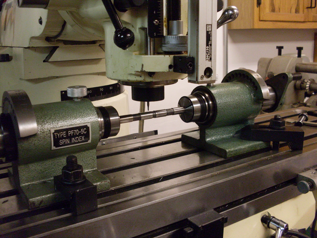
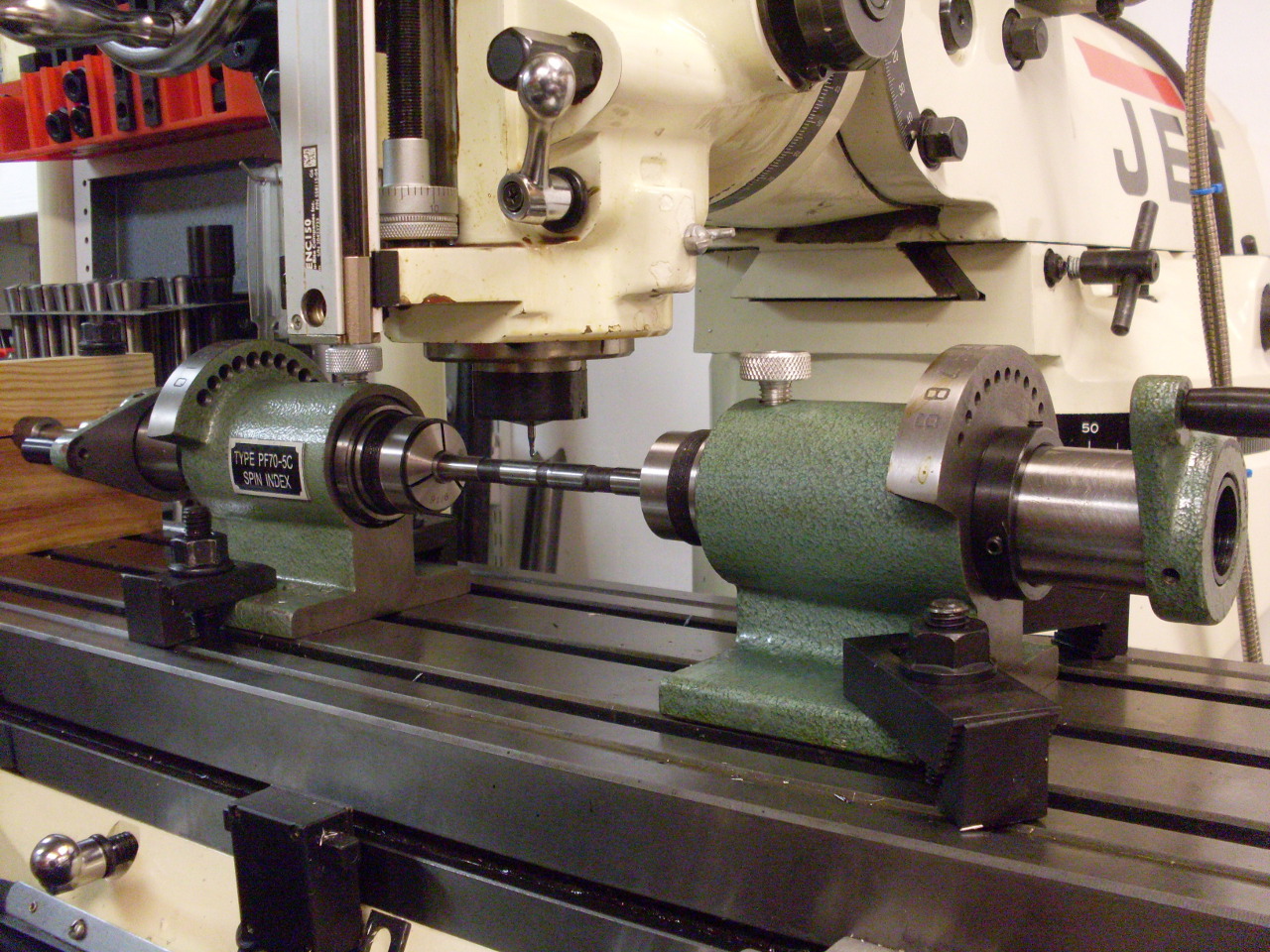
The
work (the rocker spindle) is held at each end by one of those
ubiquitous PF-70 spin indexers using 5C collets--3/8" at one end, and
9/16" at the other. I got better clearance by disassembling the
indexers and reassembling them backwards. I also took off the
index disks. I was pretty amazed that the height of the work
varied by less than 0.003" from end to end. I was prepared to
have to skim the bottom surface of one of the indexers, but it wasn't
necessary. I indicated the work to make it true with the X
travel, and tightened everything down.
The
grooves needed to be about 0.016" deep and about 0.065" wide. A
little more trig shows that a 5/64" ball end mill should do the trick,
so I ordered a couple of solid carbide units. I wasn't sure how
hard the shaft was or if HSS cutters would have a problem.
It
turned out to be pretty simple to do the actual cuts. I ran the
highest speed my mill would do (4200 RPM), and fed slowly by hand.

After
all this, my bike has better lubrication to its valve train, I've got
some new skills and experience, some tooling vendors have some more
money, and my wife thinks I did something useful. Everybody's
happy.
Comments to: elhollin1@yahoo.com